1
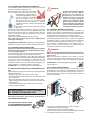
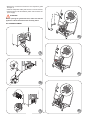
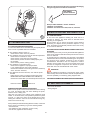
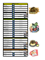
TABLE OF CONTENTS
USA
SAFETY INSTRUCTIONS ......................................................... Page
8
A.1
GENERAL INFORMATION........................................................ Page
9
A.1.1
Foreword ..................................................................................................................... Page
9
A.1.2
Intended use and limitations ...................................................................................... Page
9
A.1.3
Testing ......................................................................................................................... Page
9
A.1.4
General safety rules .................................................................................................... Page
9
A.1.5
Customer's responsibilities ....................................................................................... Page
9
A.1.6
Data plate position ...................................................................................................... Page
9
B.1
DESCRIPTION OF CYCLES ..................................................... Page
9
B.1.1
Positive blast chilling .................................................................................................. Page
9
B.1.2
Negative blast chilling or freezing ............................................................................... Page
9
B.1.3
Maintenance cycle or preservation cycle .................................................................... Page
10
B.1.4
Sterilisation cycle (appliances with germicidal light) .................................................. Page
10
C.1
ANALYSIS OF USER INTERFACE ........................................... Page 10
C.1.1
O•I I = ON / O = OFF ..................................................................................................... Page
10
C.1.2
Start/Stop cycle ............................................................................................................. Page
10
C.1.3
Select cycles ................................................................................................................ Page
10
C.1.4
Programs .................................................................................................................... Page
10
C.1.5
Temperature ................................................................................................................ Page
10
C.1.6
Alarm warning ............................................................................................................. Page
11
C.1.7
Standards .................................................................................................................... Page
11
C.1.8
Time ............................................................................................................................. Page
11
C.1.9
Utilities ......................................................................................................................... Page
11
C.1.9.1 Manual defrosting ....................................................................................................... Page
11
C.1.9.2 Probe temperatures display ....................................................................................... Page
11
C.1.9.3 "UV" Sterilisation cycle ................................................................................................. Page
11
C.1.9.4 Reference standard .................................................................................................... Page
12
C.1.9.5 User parameters ......................................................................................................... Page
12
C.1.9.6 HACCP ........................................................................................................................ Page
12
C.1.9.7 Service alarms ............................................................................................................ Page
12
C.2
USER INSTRUCTIONS ............................................................ Page 12
C.2.1
Switching on ................................................................................................................ Page
13
C.2.2
Operation ..................................................................................................................... Page
13
C.2.2.1 Selecting a standard cycle .......................................................................................... Page
13
C.2.2.2 Selecting a program .................................................................................................... Page
13
C.2.2.3 Changing the chilling time .......................................................................................... Page
14
6
C.2.2.4 Changing the chamber temperature during chilling .................................................. Page
14
C.2.2.5 Displaying the temperature setpoint and chilling end time ....................................... Page
14
C.2.2.6 Changing the Standard selection ............................................................................... Page
14
C.2.2.7 Editing USER parameters .......................................................................................... Page
14
C.2.3
Blast chilling/preservation cycle .................................................................................. Page
14
C.2.4
Defrosting .................................................................................................................... Page
14
C.2.5
Germicidal lights (Function for appliance with germicidal light option) ..................... Page
15
C.2.6
Product loading and unloading ................................................................................... Page
15
C.2.7
Inserting the food (core) probe in the product ............................................................ Page
15
C.3
STARTING THE OPERATING CYCLES ................................... Page
15
C.4
ALARMS .................................................................................... Page
17
C.4.1
Alarms ......................................................................................................................... Page
17
C.4.1.1 HACCP alarms ............................................................................................................ Page
17
C.4.1.1.1 Description of alarms .............................................................................................. Page
17
C.4.1.2 Service alarms ............................................................................................................ Page
18
C.4.1.2.1 Service alarms not requiring service center assistance ......................................... Page
18
C.4.1.2.2 Service alarms requiring service center assistance ............................................... Page
18
C.5
HACCP CONNECTIONS (ACCESSORIES) ............................. Page
18
D.1
ROUTINE MAINTENANCE ....................................................... Page
18
D.1.1
Precautions for maintenance ...................................................................................... Page
18
D.1.2
Cleaning the cabinet and accessories ....................................................................... Page
19
D.1.3
Cleaning the food (core) probe ................................................................................... Page
19
D.1.4
Precautions in the event of long periods of non-use .................................................. Page
19
D.2
MAINTENANCE TO BE PERFORMED BY TRAINED
PERSONNEL ONLY .................................................................. Page
19
D.2.1
Periodic cleaning of the condenser ............................................................................ Page
19
D.2.2
Cleaning the evaporator .............................................................................................. Page
19
D.2.3
Fan replacement ......................................................................................................... Page
20
D.3
TROUBLESHOOTING .............................................................. Page
D.3.1
Quick troubleshooting guide ....................................................................................... Page
D.4
WASTE DISPOSAL AND DEMOLITION ................................... Page
D.4.1
Waste storage ............................................................................................................. Page
21
D.4.2
Procedure for preliminary dismantling of the appliance ............................................ Page
21
D.5
ENCLOSED DOCUMENTS ...................................................... Page
21
D.6
LIST OF USER PARAMETERS ................................................ Page
22
RECIPE SELECTION ................................................................ Page
23
7
21
21
21
SAFETY INSTRUCTIONS
To reduce the risk of fire, electrical shock, or injury when using your appliance, please follow these basic
precautions including the following:
•
Read all instructions before using your appliance.
•
This Manual does not cover every possible condition and situation that may occur. Use common sense and caution
when installing, operating and maintaining this appliance.
•
FOR YOUR SAFETY DO NOT STORE OR USE GASOLINE OR OTHER FLAMMABLE VAPORS AND LIQUIDS
IN THE VICINITY OF THIS OR ANY OTHER APPLIANCE.
•
The installation of this unit must conform to local codes or, in the absence of local codes, to all National Codes
governing plumbing, sanitation, safety and good trade practices.
•
BEFORE SERVICING, DISCONNET THE ELECTRICAL SERVICE AND PLACE A RED TAG AT THE DISCONNECT
SWITCH TO INDICATE WORK IS BEING DONE ON THAT CIRCUIT.
•
NOTICE: CONTACT YOUR AUTHORIZED SERVICE COMPANY TO PERFORM MAINTENANCE AND REPAIRS.
•
NOTICE: Using any parts other than genuine factory manufactured parts relieves the manufacturer of all warranty and
liability.
•
NOTICE: Manufacturer reserves the right to change specifications at any time without notice.
•
WARNING: The equipment warranty is not valid unless the appliance is installed, started and demonstrated under
the supervision of a factory trained installer.
•
WARNING: The unit must be installed by Personnel who are qualified to work with electricity and plumbing. Improper
installation can cause injury to personnel and/or damage to the equipment. The unit must be installed in accordance
with applicable codes.
SAVE THESE
INSTRUCTIONS
8
Adjust the height and level the appliance by means of the
leveling feet, checking that the door opens and closes properly.
A.1 GENERAL INFORMATION
A.1.1 FOREWORD
The purpose of this manual is to provide the necessary
information for the correct installation, operation, use and
maintenance of the appliance.
Consequently, the manual and all the technical documentation
enclosed with the appliance must be kept with the appliance at
all times so that they can be consulted by the technician or end
user. It is important to inform the appliance user about regulations
concerning safety during and after installation.
Read the instructions in the manual carefully before carrying out
any operation whatsoever on the appliance, as they give important
information about the standards and rules governing its
installation and safe use. Improper installation, adjustment,
alteration, service or maintenance can cause property
damage, injury or death. Failure to observe the instructions
in this manual when carrying out any operations on the
appliance will relieve the manufacturer of all liability. Using
any parts other than factory manufactured parts relieves the
manufacturer of all warranty and liability.
No part of this manual may be reproduced.
A.1.2 INTENDED USE AND LIMITATIONS
This appliance has been designed for the blast chilling and/or
blast freezing and preservation of foods (it rapidly lowers the
temperature of cooked foods in order to preserve their initial
qualities over a period of time and guarantee their durability for
several days). Any other use is to be considered improper.
ATTENTION: The appliance is not suitable for installation outdoors
and/or in environments subject to atmospheric agents (rain,
direct sunlight, etc.).
The manufacturer declines all liability for any improper use of
the product.
+50 mm
+ 1.97 "
-10 mm
- 0.39 "
A.1.6 DATA PLATE POSITION
The data plate with all the appliance specifications is located on
the chilling unit compartment, on the lower left-hand side.
The plate bearing the appliance's PNC code and serial number
is located underneath the logo.
A.1.3 TESTING
Our appliances have been designed and optimised with
laboratory testing to give high performance and efficiency. The
product has gone through 100% testing and is ready for use.
The certificates guaranteeing that the tests (visual inspection electrical test - functional test) have been passed are included
with the appliance.
B.1 DESCRIPTION OF CYCLES
B.1.1 POSITIVE BLAST CHILLING
Positive blast chilling brings the food quickly to a temperature
of 37.4°F (+3°C).
Note that positive blast chilling is suitable for foods that are
going to be consumed within a few days.
There are two types of blast chilling:
A.1.4 GENERAL SAFETY RULES
The appliance is manufactured in compliance with following
directives:
- Hygiene:
ANSI / NSF 7
- Safety:
UL 471
- CAN / CSA C22.2 No.120 - M91
• “SOFT” CHILLING
• “HARD” CHILLING
- “soft” chilling is recommended for foods such as vegetables
or pieces of food that are not very large or thick.
- “hard” chilling is recommended for larger sized pieces of
food.
A.1.5 CUSTOMER’S RESPONSIBILITIES
A fused disconnect switch or a main circuit breaker
(customer furnished) MUST be installed in the electric
supply line for the appliance. It is recommended that
this switch/circuit breaker have lockout/tagout
capability. Before making any electrical connections
to this appliance, check that the power supply is adequate for the
voltage, amperage, and phase requirements on the rating plate.
B.1.2 NEGATIVE BLAST CHILLING OR FREEZING
Freezing allows foods to be preserved for longer periods (weeks
or months).
Quick freezing consists of reaching a negative temperature
(-0.4°F / -18°C) in the center of the product in the shortest
possible time. This ensures that when the product is thawed,
the tissues are not damaged and the food preserves its
aspect and nutritional ingredients.
With this cycle, the temperature of the food goes down to
between -4°F (-20°C) and -0.4°F (-18°C) when frozen.
IMPORTANT:
Level the appliance, otherwise its operation could be compromised.
9
From left to right:
B.1.3 MAINTENANCE CYCLE OR PRESERVATION CYCLE
The maintenance cycle is the maintenance of the food at a
chosen temperature so that it does not alter over time, is started
automatically at the end of the blast chilling or freezing cycle.
The preservation cycle is continuous. To interrupt it you have to
stop or make changes to the program.
• Positive "SOFT CHILLING"
• Positive "HARD CHILLING"
• Positive "COOLER" maintenance (or preservation)
• Negative "BLAST FREEZING" chilling or freezing
• Negative "FREEZER" maintenance (or preservation)
B.1.4 STERILISATION CYCLE (appliances with germicidal light
option)
The UV lamps have a direct germicidal action and are used to
sterilise the surfaces and air in the appliance chamber. This
function can be used to sterilize kitchen utensils such as knives,
carving forks, etc. (the process should be done in two steps,
turning the utensils over to make sure both sides of utensils are
sterilized) and can be activated at the end of each working day.
Do not use this function if there is food in the chamber.
When choosing a cycle, press the
button to move on to
the next option; the options are in a loop and so you can either
scroll forwards
or backwards
.
C.1.4 PROGRAMS
ATTENTION:
The appliance has a safety device that switches off the lamps
when the doors are opened. This safety device is provided
because exposure to the U. V. rays emitted by the lamps is
harmful and can cause damage to eyes.
Press the
button to set the appliance for programs
mode. The appliance switches from standard cycle selection
mode to program mode and vice versa.
C.1 ANALYSIS OF USER INTERFACE
C.1.1 O•I I = ON / O = OFF
This button indicates the status of the appliance: I=On,O=Off.
When appliance is switch on, the whole interface lights up.
From left to right:
- Program P1
- Program P2
C.1.2 START/STOP CYCLE
Associated with each standard cycle are 2 default programs that
can be varied by the user.
This button starts or stops the selected cycle.
The selected cycle starts immediately when enabled. To stop
the cycle, keep the button pressed for at least 3 seconds.
If the door is closed when a cycle is started the button will light
up continuously. If the door is opened during a cycle it will start
blinking continuously.
1- "PREP" To optimize appliance performance when the need
arises, a preparation cycle can be chosen at the beginning of
a chilling cycle which is signalled on the temperature display
by the message “PREP”.
2- If the chiller has been inactive for a long time, the compressor
will be started by impulses to guarantee maximum efficiency.
What is a program? For chilling, the user can change both the
chamber temperature and the chilling time and save the changes
in the memory for subsequent retrieval, and for maintenance the
user can set the chamber setpoint.
C.1.5 TEMPERATURE
The temperature display can display both the chamber temperature and the food (core) probe temperature.
If a cycle is running (i.e. positive or negative maintenance, timed
positive blast chilling or timed freezing), the temperature
displayed is the chamber temperature.
If a food (core) probe cycle is running, the food (core) probe
temperature will be displayed by default.
C.1.3 SELECT CYCLES
The default setting on the appliance is the SOFT chilling cycle.
Use these buttons
Press the
to select one of the following
button in chilling cycles to switch between
chamber temperature and food (core) probe temperature.
The indicator light shows which of the two temperatures is being
displayed at that time:
- if the food (core) probe temperature is displayed, the FOOD
CORE PROBE TEMPERATURE INDICATOR LIGHT switches
options:
on
- if the chamber temperature is displayed the CHAMBER TEM10
PERATURE INDICATOR LIGHT switches on
C.1.9 UTILITIES
Only one or the other can be enabled at one time. Both will not
active at the same time.
C.1.6 ALARM WARNING
The following indicator lights light up when an alarm occurs:
When the
When an HACCP alarm occurs, the indicator light
button is pressed it lights up behind. Use the
buttons to scroll backwards and forwards and select
1- blinks continuously if the alarm is current. To
check the type of alarm, scroll to the utility section
(§ C.1.9) with the keys.
2- stays on continuously if the alarm has ended but
must still be addressed by the user.
the utility. Press
to confirm.
After entering the “Utilities” menu, the system will go back to the
main menu if no button is pressed for 5 seconds.
When a service alarm occurs, the indicator light
See below for a DESCRIPTION OF THE UTILITIES FUNCTIONS.
1- blinks continuously if the alarm is current. To
check the type of alarm, scroll to the utility section
(§ C.1.9) with the keys.
2- stays on continuously if the alarm has ended but
must still be addressed by the user.
C.1.9.1 MANUAL DEFROSTING
If the appliance is in the right conditions (indicator light
The type of alarm can be displayed by using the “Utilities menu”
functions (see sections C.1.9 for an explanation of the Utilities
menu, and section C.4 for instructions on how to display the
alarm types and descriptions of the alarms).
or
enables a manual defrosting cycle. The display shows the
message “dEfr” throughout the entire cycle.
If a manual defrosting is not possible (during a chilling cycle) the
message “ UTIL NONE” will appear on the display.
The selection is enabled only in preservation/maintenance and
when selecting the operating cycle.
When the defrosting is finished the system will go back to the
main configuration.
C.1.7 STANDARDS
The Standard indicator light is normally off. It lights up only when
the Reference Standard option is entered with the UTILITIES
button.
From left to right, the lights are: Electrolux Food Safe Mode 1,
Electrolux Food Safe Mode 2, U.S. Standard .
To display the appliance Standard setting, use the “Utilities
menu” functions (see sections C.1.9 and C.1.9.4).
C.1.9.2 PROBE TEMPERATURES DISPLAY
minutes
This function displays the probe temperatures, if there is more
than one probe inserted in the product.
If just one probe is used, see section C.1.5 for instructions on
how to display the temperature.
C.1.8 TIME
C.1.9.3 "UV"STERILIZATION CYCLE
The time display shows the total and remaining chilling time.
The display is enabled only during the running or selection of
a blast chilling cycle.
The display is switched off during the setting/running of a
maintenance cycle.
The TIMED CYCLE INDICATOR LIGHT
or with the appliance on stand-by), this function
(Function for appliances with germicidal light option)
The UV lamps have a direct germicidal action and are used to
sterilize the surfaces and air in the chamber of the appliance
(see section B.1.5)
To active "UV", no cycles must be running. When the cycle is
running the “TEMPERATURE” display shows the chamber
temperature. When the cycle is finished the system goes back
to the main menu.
If a sterilization cycle is not possible because of the status of the
appliance, the message “UTIL NONE” will appear on the display.
lights up only
when a timed blast chilling cycle is running.
Set the blast chilling time in the selection stage.
11
Editing USER parameters
To edit a parameter, select the utility:
C.1.9.4 REFERENCE STANDARD
The machine can be set to 3 different Standards:
1. Electrolux Food Safe Mode 1
2. Electrolux Food Safe Mode 2
3. U.S. Standard
The default setting for the appliance is the NSF rule number
seven, which states that the product is chilled from 140°F/60°C
to 39.2°F/4°C in 240'.
Standard
Chilling start
temperature
Elect ro lux F o o d Safe M 1
Elect ro lux F o o d Safe M 2
+145.4º F (+63º C) +50º F (+10º C)
+158º F (+70º C) +37.4º F (+3º C)
90 minutes
CbSt ºC
Standard
BLAST FREEZER
Chilling start Chilling end Chilling time
temperature
temperature
Elect ro lux F o o d Safe M 2
U.S.Standard
CCEt ºC
110 minutes
CCtI minutes
+145.4º F (+63º C) -0.4º F (-18º C)
+158º F (+70º C)
CbSt ºC
-0.4º F (-18º C)
CFEt ºC
270 minutes
240 minutes
• press the
setting range;
• press the button to confirm the settings; if a selection is not
made after 5 seconds, the last value displayed will be confirmed
automatically, or press
again.
NOTE: the parameters can be edited ONLY if no cycle is running.
If a cycle is running, the utility will enable only the display of the
parameters.
The system exits the function automatically after 12 seconds if
nothing else is pressed.
C.1.9.5 USER PARAMETERS
For displaying/editing the operating parameters:
• the “TEMPERATURE” display shows the parameter label;
• the “TIME” display shows the value associated to the parameter;
•
THE REFERENCE STANDARD SELECTION CAN BE
CHANGED ONLY WHEN THERE IS NO CYCLE RUNNING. If a
chilling cycle is running the system will automatically exit the
utility.
The Standard indicator light is normally off. It lights up only when
the Reference Standard option is entered with the UTILITIES
button.
Mode setting "U.S. Standard" is conformed to the requirements
of NSF 7.
Limits are:
240 minutes;
240 minutes;
buttons to change the value within the
CFtI minutes
Section C.2.2.6 describes how to change the STANDARD (e.g.
to go from the Electrolux Food Safe Mode 1 to the Electrolux Food
Safe Mode 2).
- soft chilling =
- hard chilling =
button;
• the display blinks to show that the parameter is in ‘edit’ mode;
BLAST CHILLER
Chilling end Chilling time
temperature
U.S.Standard
Elect ro lux F o o d Safe M 1
• press the
NSF 7
140 (+60) / 39.2 (+4)
140 (+60) / 39.2 (+4)
Example of NATIONAL SANITATION FOUNDATION:
A positive blast chilling cycle with probe ends correctly if the
39.2°F (4ºC) is reached within 240'. The chilling then proceeds
either until the maintaining temperature set by the manufacturer
is reached or the user presses STOP.
The user can edit the parameter settings in the U.S. Standard
option (CbSt , CCEt, CctI, CFEt, CftI) either in USER PARAMETERS,
section C.1.9.5, or by selecting the utility directly (see section
below for instructions on how to edit the U.S. Standard
parameters).
scroll the parameters;
The system exits the function automatically after 12 seconds if
nothing else is pressed.
C.1.9.6 HACCP
Displays the chamber high temperature alarm and the blast
chilling cycle end error alarm (see section C.4. for all information
on alarms).
C.1.9.7 SERVICE ALARMS
The SERVICE ALARM function stores and displays all the
alarms, except for the chamber high temperature alarm and the
blast chilling cycle end error alarm (see sections C.4.1 for all
information on alarms).
C.2 USER INSTRUCTIONS
Before using the appliance, clean the chamber with a detergent
solution, as there may still be condensation in the chamber left
over from the final testing by the manufacturers (see section
below for information on the type of product to use).
CLEANING THE CABINET AND ACCESSORIES
It is advisable to clean the chamber every week;
increasing this frequency according
to appliance use.
Before using the unit, clean all the
internal parts and accessories with
warm water and either neutral soap
or products that are over 90%
biodegradable (in order to reduce
the emission of pollutants into the environment),
then rinse and dry thoroughly. Do not use solvent12
based detergents (e.g. trichloro-ethylene) or abrasive powders
for cleaning. Coat the metal panels with vaseline oil.
The trolleys must be cleaned with high pressure water jets.
Drain off the water used in the process of cleaning by removing
the drain plug at the bottom center of the chamber, so that the
liquid flows out into the drain tray under the cabinet. This tray
must be emptied periodically (AOFP061U, AOFP101U,
AOFP102U models).
Refit the drain plug immediately after the cleaning.
Note: make sure the drain tray has been emptied before
removing the drain plug.
START/STOP CYCLE
This button starts or stops the selected cycle.
The selected cycle starts immediately when enabled. To stop
the cycle, keep the button pressed for at least 3 seconds.
If the door is closed when a cycle is started the button will light
up continuously. If the door is opened during a cycle it will start
blinking continuously.
1- "PREP" To optimize appliance performance when the need
arises, a preparation cycle can be chosen at the beginning of
a chilling cycle which is signalled on the temperature display
by the message “PREP”.
2- If the chiller has been inactive for a long time, the compressor
will be started by impulses to guarantee maximum efficiency.
ATTENTION: the AOFP201RU model does not have a drain tray.
Make sure the drain hole is connected to the water drain system.
C.2.1 SWITCHING ON
Switch on the fused disconnet switch or the main circuit breaker
switch and press the I = ON button to start the appliance. The
I = ON indicator light lights up to signal that the appliance is
powered up.
Consequently, if a timed cycle starts, after 2 minutes the TIME
INDICATOR LIGHT will switch on and the CHAMBER TEMPERATURE will be displayed by default.
C.2.2.2 Selecting a program:
First of all, the user has to decide what kind of cycle to launch
(SOFT, HARD, etc.) and then select the program.
Go through the following steps:
• Select the type of cycle;
C.2.2 OPERATION
C.2.2.1 Selecting a standard cycle
The default setting on the appliance is the SOFT chilling cycle.
Use these buttons
to select one of the following
options:
• Press the program select button
From left to right:
light
• Positive "SOFT CHILLING"
• Positive "HARD CHILLING"
• Positive "COOLER" maintenance (or preservation)
• Negative "BLAST FREEZING" chilling or freezing
• Negative "FREEZER" maintenance (or preservation)
When choosing a cycle, press the
or backwards
lights up.
• if the type of program is right, start it by pressing button
• keep pressing the select button
until the chosen
.
program indicator light
If you want another cycle, keep pressing the
switches on.
button until
the indicator light for the chosen cycle turns orange, and start it
by pressing the
.
if not
button to move on to the
next option; the options are in a loop and so you can either scroll
forwards
; the program indicator
• to start the program, press the
button.
button.
The user can edit some of the cycle parameters and save the
changes:
IMPORTANT:The appliance recognizes automatically when the
food (core) probe is inserted in to the product. If the probe hasn’t
been inserted in to the product, a timed cycle will start
automatically.
It is necessary to wait 2 minutes after the end of the preparation
cycle for the automatic recognition (see section below).
- for blast chilling, the user can edit the chamber chilling time/
setpoint and save it in the memory, from where it can
subsequently be retrieved (see section C.2.2.3 and C.2.2.4).
- for positive maintenance, the user can set the chamber
setpoint.
13
C.2.2.3 Changing the chilling time
The chilling time can be edited in two situations:
1) when setting a program (P1 o P2)
2) when selecting a chilling cycle.
the Standard
either press the
confirm the selection or it will be confirmed automatically if
nothing is pressed for 12 seconds.
THE CHILLING TIME CAN NEVER BE EDITED WHEN A CYCLE
IS RUNNING.
To change the time, proceed as follows:
C.2.2.7 Editing USER parameters
To edit a parameter, select the utility:
• press the
• press the
button for 2 seconds;
• press the
setting range;
• press the button to confirm the settings; if a selection is not
made after 5 seconds, the last value displayed will be confirmed
button to confirm the setting, if a selection
automatically, or press
C.2.2.4 Changing the chamber temperature during chilling
In custom cycles only, the setpoint can be changed with the
following procedure:
See section D.6 for the “List of user parameters”.
C.2.3 BLAST CHILLING/PRESERVATION CYCLE
When the chilling or freezing cycle has finished, the appliance
will automatically go into the preservation stage. It is important
for the chilled food to be kept in an appropriate way, maintaining
a preservation temperature suitable for the type of food chilled.
• the display blinks to signal that you are in “edit” mode;
• press the
buttons;
C.2.4 DEFROSTING
button to confirm the setting, if a selection
is not made after 5 seconds, the last value displayed will be
confirmed automatically.
If the appliance is in the right conditions (indicator light
C.2.2.5 Displaying the temperature setpoint and chilling end
time
When a cycle is running, the user can view the temperature
setpoint and chilling end time by pressing buttons
or
C.2.2.6 Changing the Standard selection
To select a Standard, e.g. the Electrolux Food Safe Mode 2,
button, press the
or with the appliance on standby), this function
enables a manual defrosting cycle. The display shows the
message “dEfr” throughout the entire cycle.
If a manual defrosting is not possible (during a chilling cycle) the
message “UTIL NONE” will appear on the display.
The selection is enabled only in preservation/maintenance and
when selecting the operating cycle.
When the defrosting is finished the system will go back to the
main configuration. The cycle times and the intervals between
defrostings are preset by the manufacturer.
and
simultaneously.
press the
- Manual defrosting
To start a manual defrosting, proceed as follows:
button until the
• PRESS THE
Standard utility is selected,
press the
button to enter, press the
again.
NOTE: the parameters can be edited ONLY if no cycle is running.
If a cycle is running, the utility will enable only the display of the
parameters.
button for 2 seconds;
• set the value with the
buttons to change the value within the
• press the
buttons;
is not made after 5 seconds, the last value displayed will be
confirmed automatically.
• press the
button;
• the display blinks to show that the parameter is in ‘edit’ mode;
• the display blinks to signal that you are in “edit” mode;
• set the value with either the
button again to
BUTTON; THE DEFROSTING INDICATOR
LIGHT WILL TURN ORANGE, THE REST WILL STAY GREEN.
button to select
• PRESS
14
AGAIN TO CONFIRM.
To shorten the defrosting time, the function can be run with the
door open, or a manual defrosting can be started with the chiller
door open; in this way the chiller internal fans will start up to draw
air into the chamber from the outside, thus shortening the
defrosting times.
For further information see following section.
MANUAL DEFROSTING
If the appliance is in the right conditions (indicator light
or
or with the appliance on stand-by), this function
enables a manual defrosting cycle. The display shows the
message “dEfr” throughout the entire cycle.
If a manual defrosting is not possible (during a chilling cycle) the
message “UTIL NONE” will appear on the display.
The selection is enabled only in preservation/maintenance and
when selecting the operating cycle.
When the defrosting is finished the system will go back to the
main configuration.
Before each defrosting, remove the drain plug from the bottom
of the chamber. Replace the plug after defrosting.
C.2.5 GERMICIDAL LIGHTS (Function for appliances with
- Type of tray to be used. It is advised to use shallow trays (i.e.
with sides no higher than 2.5"/65 mm) to allow good air circulation
around the product (the greater the surface area of the food
exposed to the air, the shorter the chilling time). You are advised
to clean the trays and tray support surfaces thoroughly to avoid
food contamination. You are also advised to put the food in the
chiller in the same tray that it was cooked in.
C.2.7 INSERTING THE FOOD (CORE) PROBE IN THE PRODUCT
Make sure the probe is clean and sterilized whenever inserting
it in food, and always take care when handling the probe,
because it has a sharp point.
Using the food (core) probe in the chilling cycles guarantees
good results. To be certain of this, it is important to position the
probe correctly, i.e. right at the center of the largest piece of food,
making sure it doesn’t come out the other side and being very
careful not to touch the tray.
germicidal light option)
To enable the lights, the appliance must be switched on but with
no cycle running.
Press
using the
button to select the
cycle.
The corresponding indicator light turns orange;
press the
button again to confirm the selection and
start the cycle by pressing the
button.
You are advised to run a germicidal cycle at the start of the day
before using the appliance, and another one at the end of the day
after cleaning the chamber.
For further information see sections B.1.5 and C.1.9.6.
ATTENTION: The cycle will not be enabled if the chamber
temperature is less than 59°F (15°C) or if the door is open.
THE EFFICIENT OPERATION OF THE APPLIANCE IN THE BLAST
CHILLING AND FREEZING CYCLES DEPENDS ON THE
FOLLOWING FACTORS:
C.2.6 PRODUCT LOADING AND UNLOADING
Use kitchen gloves when loading and unloading food. It is not
advisable to keep the food covered during the chilling cycle in
order to facilitate chilling. An even distribution of the food inside
the chamber allows good air circulation and therefore better
preservation of the food.
In any case, do not leave the door open longer than necessary
when removing or loading food.
At the end of the cycle, open the door and remove the probe,
putting it back in its original position (remember that the pans
are cold, therefore use gloves).
C.3 STARTING THE OPERATING CYCLES
To get familiar with the chiller's electronic board as quickly as
possible, we have provided a series of step-by-step instructions
on how to enable the various functions.
When switched on, the appliance sets up for the SOFT chilling
cycle by default.
You can now select the cycle by pressing the
button,
according to the following instructions:
- Hard chilling:
• PRESS THE BUTTON
15 ORANGE
UNTIL THE
LIGHT TURNS
LIGHT TURNS
• PRESS THE
ORANGE
CYCLE BUTTON
• PRESS THE
If the probe hasn’t been inserted in the product, the cycle will be
timed.
CYCLE BUTTON
- Hard chilling with program select and chilling time change:
- Hard chilling with chilling end time change:
• PRESS THE
• PRESS THE BUTTON
UNTIL THE
LIGHT TURNS
BUTTON UNTIL THE
LIGHT TURNS
ORANGE
ORANGE
IF YOU WANT TO CHANGE THE CHILLING END TIME
• PRESS THE
BUTTON FOR 2 SECONDS
• THE
• PRESS THE
BUTTON.
• PRESS THE
IF THE PROGRAM SELECTED IS OK
BUTTON TO SELECT THE VALUE. IF
A SELECTION IS NOT MADE AFTER 5 SECONDS THE LAST
VALUE DISPLAYED WILL BE CONFIRMED AUTOMATICALLY
OR YOU CAN CONFIRM BYPRESSING THE
INDICATOR LIGHT LIGHTS UP
• PRESS THE
CYCLE BUTTON
IF YOU WANT TO CHANGE THE TYPE OF PROGRAM
BUTTON
AGAIN.
• PRESS THE
• PRESS THE
LIGHT TURNS
- Hard chilling with program select:
• PRESS THE
INDICATOR
BUTTON UNTIL THE
ORANGE
• PRESS THE
BUTTON FOR 2 SECONDS
LIGHT TURNS
• PRESS THE
ORANGE
• PRESS THE
BUTTON UNTIL THE
CYCLE BUTTON
BUTTON.
BUTTON TO SET THE CHOSEN TIME
BUTTON AGAIN TO SAVE THE
EITHER PRESS THE
NEW SETTING OR IT WILL BE CONFIRMED AUTOMATICALLY
IF NOTHING IS PRESSED FOR 5 SECONDS, AND THEN
• THE
INDICATOR LIGHT LIGHTS UP
PRESS THE
CYCLE BUTTON
IF THE PROGRAM SELECTED IS OK
IF YOU WANT TO CHANGE THE CHAMBER TEMPERATURE
• PRESS THE
CYCLE BUTTON
• PRESS THE
BUTTON FOR 2 SECONDS
IF YOU WANT TO CHANGE THE TYPE OF PROGRAM
• SET THE CHOSEN TIME
• PRESS THE
BUTTON UNTIL THE
INDICATOR
16
• EITHER PRESS THE
BUTTON AGAIN TO SAVE THE
NEW SETTING OR IT WILL BE CONFIRMED AUTOMATICALLY
IF NOTHING IS PRESSED FOR 5 SECONDS, AND THEN PRESS
THE
CYCLE BUTTON.
where (number) indicates the current day’s batch number, Start
Date Time indicates the cycle start and End Date Time the cycle
end.
WHAT IS A BATCH NUMBER? Each blast chilling cycle (SOFT/
HARD chilling, freezing) will be identified by a progressive
number(1,2, ... ), known as the “BATCH NUMBER”. This refers
to the current day and will be reset to ‘0’ at the start of each new
calendar year.
N.B. There are no cycle end alarms in timed chilling/freezing.
C.4 ALARMS
IMPORTANT:
in the event of a power failure, the display shows the “no
C.4.1 ALARMS
The electronic board manages two kinds of alarm system:
- HACCP for monitoring and storing high temperature alarms.
HACCP alarm states are signalled by the sounding of the
buzzer, the blinking of the red HACCP indicator light and the
appearance of an alarm message on the display.
- SERVICE ALARMS for storing and managing all the alarms on
the electronic board (except the high temperature and blast
chilling cycle end error alarms).
. This alarm can be
power” alarm with red indicator
displayed by scrolling with the utility keys. The appliance will
then restart from exactly where it stopped.
To display the alarm, enter the utility and use the
C.4.1.1 HACCP ALARMS
For managing the chamber high temperature alarm and the
blast chilling cycle end error alarm.
buttons to scroll until the messages appear: “AL 1”, “AL 2” and
so on.
After displaying the last alarm,
the ‘——’ message will appear on the alarm display, and if
nothing is pressed for 12 seconds the unit will automatically go
back to the main menu.
If there is no current alarm: the “TEMPERATURE” display
reads ‘none’, and the “TIME” display is switched off.
To cancel the alarms, press
If there is a current alarm the “TEMPERATURE” display shows
the alarm number “ AL 1”, AL 2", etc., and the “TIME” display
gives the description of the alarm (see section below).
DESCRIPTION OF ALARMS
- HIGH TEMPERATURE ALARM
The display shows:
• the “Batch (number) Ht (maximum temperature reached) °F/
°C Start Date Time End —-”, if the alarm is still active
e.g. Batch 01 Ht 59°F / 15°C Start 25-10-01 15.48 End ——
• the “Batch (number) Ht (maximum temperature reached) °F/
°C Start Date Time End Date OrTime”, if the alarm has ended
e.g. Batch 01 Ht 59°F / 15°C Start 25-10-01 15.48 End 25-1001 17.48
where:
Start Date Time indicates the start of the alarm, End Date Time
indicates the end of the alarm (“Date” format: DD-MM-YY, “Time”
format: HH.MM; ).
- CHILLING CYCLE END ERROR ALARM
This check ensures that a food (core) probe blast chilling/
freezing cycle ends correctly.
If a cycle does not end correctly, a “Chilling time out of limits”
alarm is generated and the display reads:
Batch (number) Ot (chilling time)MIN Start Date Time End date
Time”
e.g. BATCH1 Ot 250MIN Start 25-10-01 15.48 End 25-10-01
19.58.
+
together for 5
seconds.
ATTENTION: The reset function is disabled if the operator did not
see the stored alarms. When the reset function is enabled the
message “RES” appears on the TEMPERATURE display.
C.4.1.1.1 DESCRIPTION OF ALARMS
- HIGH TEMPERATURE ALARM
The display shows:
• the “Batch (number) Ht (maximum temperature reached) °F/
°C Start Date Time End —-”, if the alarm is still active
e.g. Batch 01 Ht 59°F / 15°C Start 25-10-01 15.48 End ——
• the “Batch (number) Ht (maximum temperature reached) °F/
°C Start Date Time End Date OrTime”, if the alarm has ended
e.g. Batch 01 Ht 59°F / 15°C Start 25-10-01 15.48 End 25-1001 17.48
where:
Start Date Time indicates the start of the alarm, End Date Time
indicates the end of the alarm (“Date” format: DD-MM-YY, “Time”
format: HH.MM; ).
- CHILLING CYCLE END ERROR ALARM
This check ensures that a food (core) probe blast chilling/
freezing cycle ends correctly.
If a cycle does not end correctly, a “Chilling time out of limits”
alarm is generated and the display reads:
Batch (number) Ot (chilling time)MIN Start Date Time End date
Time”
e.g. BATCH1 Ot 250MIN Start 25-10-01 15.48 End 25-10-01
17 19.58.
where (number) indicates the current day’s batch number, Start
Date Time indicates the cycle start and End Date Time the cycle
end.
Use the
WHAT IS A BATCH NUMBER? Each blast chilling cycle (SOFT/
HARD chilling, freezing) will be identified by a progressive
number(1,2, ... ), known as the “BATCH NUMBER”. This refers
to the current day and will be reset to ‘0’ at the start of each new
calendar year.
After displaying the last alarm, the “——” message will appear
on the display and after 12 seconds the unit will automatically
go back to the main menu.
When the next alarm occurs, the current ones will be cancelled
(automatic reset).
N.B. There are no cycle end alarms in timed chilling/freezing.
If an alarm is active, going into the utility will silence the buzzer
and simultaneously access the alarm message display.
IMPORTANT:
in the event of a power failure, the display shows the “no
power” alarm with red indicator
Use the
. This alarm can be
C.4.1.2 SERVICE ALARMS
There are two types of service alarm:
- type “b” (user) which do not require service center assistance
(see section C.4.1.2.1) and do not shut down the appliance;
B1
B2
B3
B4
DES CRIP TION
C.5 HACCP CONNECTIONS
(ACCESSORIES)
ACTION
Condens er temperature Clean condens er; c hec k air
high
circ ulation around
condenser
Door open
Clos e door
Mem ory full
Reset HA CCP alarms
P ower failure
Chec k plug properly
ins erted in power supply
soc ket;
Chec k elec trical s ystem
Refer to the handbook enclosed with the kit for instructions
on installing the accessories.
The board has a serial communication line for interacting with
other units, printers or a HACCP control station in a network.
This can be connected in the following ways:
• directly to a device that communicates in TTL (e.g. the FT190ELX
printer), by setting the parameter E485=”Prn”
• to an RS485 communications network, by setting the parameters
E485=”PC” and using the conversion card RS485-LK-P and
Adr=”Network address”.
- type “E” (non-user) for which you are advised to call the service
center for assistance (see section C.4.1.2.2), but which do not
shut down the appliance.
E1
E2
E3
E4
E5
E6
E7
E8
E9
E10
E13
DESCRIPTION
M inim um cham ber tem perature
M inim um evaporator temperature
Chamber probe malfunctioning or disconnected
Evaporator probe malfunctioning or disconnected
Am bient probe m alfunctioning or disconnected
Condenser probe m alfunctioning or disconnected
Core probe 1 m alfunctioning or disconnected
Core probe 2 m alfunctioning or disconnected
Core probe 3 m alfunctioning or disconnected
Pressure switch tripped
Internal clock m alfunction
D.1 ROUTINE MAINTENANCE
ACTION
CALL SERVICE CENTER
SYM BOL
buttons to scroll the stored alarms.
After displaying the last alarm, the l “——” message will
appear on the display and after 5 seconds the unit will
automatically go back to the main menu.
The function for cancelling from the memory is disabled when
there are alarms active (i.e. the reset is disabled).
displayed by scrolling with the utility keys. The appliance will
then restart from exactly where it stopped.
S YMBOL
buttons to scroll the stored alarms.
D.1.1 PRECAUTIONS FOR MAINTENANCE
Routine maintenance tasks can be performed by nonspecialised personnel. When performing maintenance please
follow the instructions closely, keeping safe at all time. The
manufacturer declines any responsibility for injury sustained
from unsafe acts.
ATTENTION:
do not touch the appliance if hands
and/or feet are wet. Before
performing any cleaning or
maintenance disconnect the
appliance from the electrical
source and carefully unplug the
appliance. It is DANGEROUS AND
UNADVISEABLE to remove the
safety guards, AND IS NOT
REQUIRED
for
routine
maintenance. Wear protective
gloves when cleaning the condenser. Do not use scissors,
screwdrivers and sharp objects on the cooling circuit.
C.4.1.2.1 Service alarms not requiring service center
assistance
C.4.1.2.2 Service alarms requiring service center assistance
When the alarms listed below occur, call the service center for
assistance.
All alarms will be stored as follows: the “TEMPERATURE”
display shows the alarm number, e.g. “AL 1”, “AL 2”, etc.,
whereas the “TIME” display shows the ALARM CODE, e.g. “E1”,
“b1”, etc....
If no alarm is active: the first alarm, i.e. the last to occur, is
displayed.
18
D.1.2 CLEANING THE CABINET AND ACCESSORIES
It is advisable to clean the chamber every week; increasing this
frequency according to appliance use.
Before using the unit, clean all the internal parts
and accessories with warm water and either
neutral soap or products that are
over 90% biodegradable (in order to
reduce the emission of pollutants
into the environment), then rinse
and dry thoroughly. Do not use solvent-based
detergents (e.g. trichloro-ethylene) or abrasive
powders for cleaning. Coat the metal panels with
vaseline oil.
The trolleys must be cleaned with high pressure
water jets.
Drain off the water used in the process of cleaning by removing
the drain plug at the bottom center of the chamber, so that the
liquid flows out into the drain tray under the cabinet. This tray
must be emptied periodically (AOFP061U, AOFP101U,
AOFP102U models).
Refit the drain plug immediately after the cleaning.
Note: make sure the drain tray has been emptied before
removing the drain plug.
ATTENTION: the AOFP201RU model does not have a drain tray.
Make sure the drain hole is connected to the water drain system.
D.1.3 CLEANING THE FOOD (CORE) PROBE
Pay particular attention when handling the probe; remember
that it has a sharp point, therefore handle it with extreme care,
even in the cleaning phase.
You are advised to clean the food (core) probe periodically to
make sure the appliance works at maximum efficiency.
The probe must be cleaned by hand, using warm water and
either neutral soap or products that are over 90% biodegradable
(in order to reduce the emission of pollutants into the
environment), then rinse thoroughly with clean water and
disinfectant solution. Do not use solvent-based detergents (e.g.
trichloro-ethylene) or abrasive powders for cleaning.
ATTENTION: do not use boiling water to clean the probe.
D.1.4 PRECAUTIONS IN THE EVENT OF LONG PERIODS OF NONUSE
If the appliance is not going to be used for a long period, take the
following precautions:
• Unplug the plug from the electricity mains socket.
• Remove all food from the chamber and clean the interior and
the accessories.
• Rub all the stainless steel surfaces vigorously with a cloth
slightly dampened with vaseline oil, so as to cover them with
a protective film.
• Leave the door partially open to allow the air to circulate.
• Air the premises regularly.
ATTENTION:
do not touch the appliance if hands
and/or feet are wet. Before
performing any cleaning or
maintenance disconnect the
appliance from the electrical
source and carefully unplug the
appliance. Do not remove safety
guards. Wear protective gloves
when cleaning the condenser. Do
not use scissors, screwdrivers and
sharp objects on the cooling circuit.
D.2.1 PERIODIC CLEANING OF CONDENSER
The condenser can be cleaned with a brush, provided the
bristles are not in steel or a material that can compromise good
operation. Take maximum care not to bend the condenser fins,
as this would cause a reduction in the heat exchange.
If the appliance is to work efficiently, the chilling unit condenser
must be cleaned at least once every 3 months. If the appliance
is installed in a dusty or poorly ventilated environment the filter
must be cleaned more frequently, i.e. about once a month.
The condenser is located behind the front slotted panel. To
remove it, take out the two screws at the bottom and pull it
outwards to release it from the holding clips.
ATTENTION:
Before removing the slotted panel that protects the condenser,
make sure the appliance has been disconnected from the
power source.
Note: The technician is advised to use a brush or vacuum
cleaner to remove the dirt accumulated on the condenser. Do
not use pointed objects, as they may damage the condenser.
ATTENTION: Do not wash the appliance by squirting
a jet of water on it.
D.2.2 CLEANING THE EVAPORATOR
Even in this case cleaning can be done with a brush, provided
the bristles are not in steel or a material that can compromise
good operation of the evaporator. Take maximum care not to
bend the evaporator coil fins, as this would cause a reduction
in the heat exchange.
D.2 MAINTENANCE TO BE PERFORMED
BY TRAINED PERSONNEL ONLY
Non-routine maintenance tasks must be perfomed by an
AUTHORIZED SERVICE AGENT.
USE APPROPRIATE SAFETY GEAR
(GLOVES AND MASK) WHEN CARRYING
OUT ANY MAINTENANCE OPERATION.
To access the evaporator battery, proceed as follows:
• Disconnect from the power supply;
• Remove any trays from inside the chamber;
• Remove the 4 screws (2 in front and 2 behind) that secure the
19 two deflector plates to the evaporator guard;
• Remove the 2 screws that secure the inner inspection guard
and open it;
• Clean the evaporator battery with a brush or vacuum cleaner;
• Close the guard, refit the deflector plates and reconnect the
power supply.
ATTENTION:
Before opening the guard with tools, make sure that the
appliance is disconnected from the electricity mains.
D.2.3 FAN REPLACEMENT
4
1
5
FIG. 2
2
FIG. 3
3
6
20
Note: the code and serial number are essential for identifying
the type of appliance and date of manufacture.
PNC 726299
Ser.No.41000010
Example: PNC 726299 00 - Ser.No. 41000010
726299 00: chiller R404A
41000010: manufactured in 2004, week 10, 10th item.
D.4 WASTE DISPOSAL AND DEMOLITION
D.4.1 WASTE STORAGE
At the end of the appliance’s working life, make sure it is
disposed of properly. The doors must be removed before
disposing of the appliance.
Special waste can be stored temporarily whilst awaiting
processing for disposal and/or permanent disposal. In any
event, the binding environmental protection laws in the country
of use must be observed.
7
D.3 TROUBLESHOOTING
D.3.1 QUICK TROUBLESHOOTING GUIDE
In some cases faults can be remedied easily and quickly. Below
there is a list of possible faults and remedies:
D.4.2 PROCEDURE FOR PRELIMINARY DISMANTLING OF THE
APPLIANCE
The laws vary from country to country, but the laws and regulations
in the country where the demolition takes place are the ones that
must be observed.
In general terms, the refrigerator must be taken to specialised
collection/demolition centers, after dismantling the components
and grouping them together according to their chemical
characteristics. Remember that the compressor contains
lubricant oil and coolant, which can be recovered and re-used
and that the refrigerator components are classed as special
waste that cannot be assimilated with urban waste.
A. The appliance doesn’t switch on:
- check that the mains socket is powered.
B. The appliance does not reach the set internal temperature:
- check that the condenser is clean;
- check that the cycles have been set properly;
- check that the product has been loaded properly into
the chamber;
- check that the probe is working properly.
C. The appliance is excessively noisy:
- check that the appliance is properly levelled.
If it is unbalanced this could cause vibrations.
- check that the cabinet is not touching other units, as this may
cause resonant vibrations;
D. The appliance functions with time, even with the probe
inserted:
- make sure the probe is correctly inserted (see below INSERTING THE CORE PROBE IN THE PRODUCT);
- check that 5 minutes after cycle start with probe inserted, the
luminous indicator
ATTENTION:
Make the appliance unusable by removing the power supply
cable and any device that closes the internal compartments, to
avoid the possibility of somebody getting trapped inside.
THE DISMANTLING MUST BE DONE BY QUALIFIED PERSONNEL.
D.5 ENCLOSED DOCUMENTS
remains off.
• Set of test documents
• Wiring diagram
INSERTING THE CORE PROBE IN THE PRODUCT
Make sure the probe is clean and sterilized whenever inserting
it in food, and always take care when handling the probe,
because it has a sharp point.
Using the core probe in the chilling cycles guarantees good
results. To be certain of this, it is important to position the probe
correctly, i.e. right at the center of the largest piece of food,
making sure it doesn’t come out the other side and being very
careful not to touch the tray.
If the problem persists after making all these checks, contact the
service center, remembering to give the following details:
• the kind of fault;
• the appliance’s PNC (production number code);
• the Ser. No. (appliance serial number).
21
D.6 LIST OF USER PARAMETERS
SYMBOL
MIN
HOUR
DAY
MON
YEAR
SrF
SFF
CdiF
Internal clock: Minutes
Internal clock: Hours
Internal clock: Day
Internal clock: Month
Internal clock: Year
Indicates the chamber tem perature setpoint for the positive m aintenance cycle
and preservation stage after positive chilling.
Indicates the chamber tem perature setpoint for the negative maintenance cycle
and preservation stage after negative chilling.
Indicates whether the LAC and HAC temperature limits are expressed in
differential (d) or absolute m ode (A).
RANGE
0..59
0..23
1..31
1..12
0..99
-25..10°C/F
DEF.
0
0
1
1
0
3
-25..10°C/F
-25
A/d
D
LAC
Tem perature delta for preservation/absolute temperature setting under which a
low tem perature alarm will be generated
-50..125°C/F
5
HAC
Tem perature delta for preservation/absolute temperature setting above which a
high temperature alarm will be generated
-50..125°C/F
5
SLd
Indicates the duration of the sterilisation cycle
0..240
10
Nob
bbl
lbl
bbl
bCCy
bFCy
bAll
CCEt
CCtI
CFEt
CFtI
CbSt
tPrA
tPrC
Adr
E485
nOr
REL
Buzzer m odes for signalling the satisfactory end of a chilling cycle
'nob' = buzzer off;
'bbl' = buzzer on for 30 seconds;
"llb" = buzzer on until any button is pressed
Buzzer m ode for signalling HACCP alarms
Buzzer m ode for signalling a general alarm
U.S. Standard: POSITIVE CHILLING END TEMPERATURE
U.S. Standard: POSITIVE CHILLING END TIME
U.S. Standard: NEGATIVE CHILLING END TEMPERATURE
U.S. Standard: NEGATIVE CHILLING END TIME
U.S. Standard: CHILLING START TEMPERATURE
Indicates the printing interval during a chilling cycle. If set to 0 only the
temperatures at the start and end of the cycle are printed.
Indicates the preservation/maintenance printing interval. If set to 0 no values
are printed.
Network address.
Connection time:
Prn = Printer;
PC = Personal Com puter;
3 values are available:
nF means Electrolux Food Safe Mode 1
Uk means Electrolux Food Safe Mode 2
CuSt m eans U.S. Standard
Software version.
N.B. The default parameters (DEF.) may vary for different
appliance models.
22
0..CbSt°C/F
0..360 m in
-35..CbSt°C/F
0..360°C/F
0..127°C/F
1..255 m in
bbl
lbl
4
240
4
240
60
5
1..255 m in
30
01-FF
Prn/PC
Prn
nF, Uk, CuSt
CuSt
-
-
1
RECIPE SELECTION
Meat / Poultry / Game
Roast Beef
6.6 - 9.9 lb (3 - 4,5 kg) piece
2 per rack
with probe
6.6 - 9.9 lb (3 - 4,5 kg) piece
2 per rack
with probe
Roast Pork
Rack of lamb
with probe
(5 - 6 pt)
10 per rack
Beef casserole
with probe
Lamb casserole
with probe
Pork casserole
with probe
Cottage pie
with probe
brush top
with melted butter
Bacon slices
check after 6'
arranged
on 0.79 in (20 mm) trays
Roast chicken
with probe
2.2 - 4.4 lb (1 - 2 kg) piece
11 - 13.2 lb (5 - 6 kg) per rack
Roast duck
with probe
3 per rack
Stuffed chicken breast
with probe
12 per tray
GN 0,79 in (20 mm)
Chicken breast (fresh)
with probe
12 per tray
GN 0.79 in (20 mm)
Chicken legs
with probe
15 per rack
Hamburger
check after 20'
0.22 lb (100 g) each
15 per tray GN 0.79 in (20 mm)
Meat terrine
with probe
2 terrines
per rack
Veal shoulder roast
1 joint per rack
Not suitable in one piece. Cut into 4.4 - 6.6 lb (2 - 3 kg) size,
hard with probe
Ox tongue
with probe
11 lb (5 kg) per 2.56 in (65 mm)
GN pan
Hare / Rabbit
with probe
8.8 lb (4 kg) per GN pan
Kebab (chicken, beef, lamb)
check after 12 - 15'
cook time depends on size of meat
pieces (GN 0.79 in / 20 mm pans)
Boned, stuffed rolled loin of pork
with probe
2 pieces per GN
1.57 in (40 mm) pan
Seafood
Fish kebab
0.79 in (20 mm) tray with grid
Approximately 4.4 lb (2 kg) per tray
check after 10'
Salmon fillets poached
1.57 in (40 mm) pans, 15 fillets per pan
depends on size
check after 10'
Seafood terrine
on wire grids,
3 per grid
with probe
Fish fillets
If regenerated, with probe
0.79 in (20 mm) pans - solid
Fish balls
0.79 in (20 mm) pans - solid
50 per pan
with probe
23
Farinaceous dishes
Quiche
with probe
number per grid
depends on size
Vegetable au gratin
with probe
in 1.57 in (40 m m ) GN pan
Rice - pilaf style
with probe (stir rice every 5 - 8')
2.56 in (65 mm ) pan,
1.5 litre hot stock per 2.2 lb (1 kg) rice
Lasagne
with probe
2.56 in (65 mm ) pans,
11 lb (5 kg) each
Vegetable lasagne
with probe
2.56 in (65 mm ) pans,
6.6 lb (3 kg) each
Baked pasta
with probe
2.56 in (65 mm ) pans,
6.6 lb (3 kg) each
Gnocchi alla romana
If regenerated, with probe
1.57 in (40 mm ) pans
Vegetables
Asparagus
check after 10'
0.79 in (20 mm) perforated pans,
3.3 lb (1.5 kg) per pan
Beans (fresh)
check after 10'
1.57 in (40 mm) perforated,
5.5 lb (2.5 kg) per pan
Beans (frozen)
check after 10'
1.57 in (40 mm) perforated,
5.5 lb (2.5 kg) per pan
Broccoli (fresh)
check after 10'
1.57 in (40 mm) perforated,
3.3 lb (1.5 kg) per pan
Cauliflower
check after 10'
1.57 in (40 mm) perforated,
4.4 lb (2 kg) per pan
Cabbage shredded
check after 10'
1.57 in (40 mm) perforated,
5.5 lb (2.5 kg) per pan
Mousaka
with probe
0.79 in (20 mm) solid pans
Leeks
check after 10'
1.57 in (40 mm) perforated,
4.4 lb (2 kg) per pan
Stuffed peppers
1.57 in (40 mm) solid pans
20 pieces per pan
with probe
Desserts
Bread and butter pudding
with probe
2.56 in (65 mm) solid pans,
24 - 30 portions
Din cake
check after 10'
0.79 in (20 mm) solid trays,
2.2 - 6.6 lb (1 - 3 kg) butter on each
Crème caramel
with cover on, check after 15'
1.57 in (40 mm) solid pans, 18 - 24 pieces
per pan. Cover with cling wrap
Fruit crumble
with probe
2.56 in (65 mm) solid
24 - 30 portions per pan
Poached apples and pears
with probe
in vacuum bags with syrup, spice
Cooked on grids
Miscellaneous
Boiled eggs
0.79°F (20°C) perforated tray, 60 eggs
per tray (time depends on soft/hard)
place in cold water
Idaho potatoes
on wire grids, do not stack on top of each
other
with probe
Scotch eggs
double crum b 0.79 in (20 mm ) tray,
24 - 30 per tray
with probe
24