1
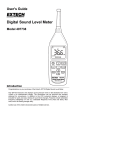
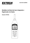
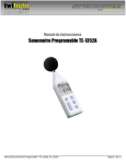
User's Guide Digital Datalogging Sound Level Meter Model HD600 Introduction Congratulations on your purchase of the Extech HD600 Digital Sound Level Meter. This meter measures and displays sound pressure levels in dB (decibels) from 30 to 130dB in three measurement ranges. In addition to the LCD numerical displays, a bargraph is included for quick and easy viewing of sound level changes. Features include selectable Frequency Weighting (‘A’ and ‘C’), selectable Response Time (Fast and Slow), Max/Min Hold, and AC/DC analog outputs. PC cable and software enable the user to download and analyze measured data. This meter is shipped fully tested and calibrated and, with proper use, will provide years of reliable service. Safety Read the following safety information carefully before attempting to operate or service the meter. Use the meter only as specified in this manual; otherwise, the protection provided by the meter may be impaired. Environmental Conditions Altitude up to 2000 meters Relative Humidity: 90% max Operating Temperature: 32 to 104°F (0 to 40°C Maintenance and Cleaning Servicing not covered in this manual should be performed by qualified personnel. Periodically wipe the case with a dry cloth. Do not use abrasives or solvents. 2 HD600–en-GB_V1.4 04/15 Meter Description 1. Windscreen 2. LCD Display 3. Setup-button: 4. Record button 5. A/C weighting 6. Max/Min display 7. Range button 8. Microphone 9. Backlight 10. Fast/Slow response 11. HOLD 12. ON/OFF Tripod Mount (rear) Battery Compartment (rear) SIDE PANEL 13. External 9VDC power adaptor 14. USB pc port 15. DC/AC analog output 16. CAL potentiometer DISPLAY Symbol MAX MIN OVER UNDER FAST SLOW dBA dBC REC AUTO FULL HOLD Function Maximum hold Minimum hold Over range Under range Fast response Slow response A-Weighting C-Weighting Recording data Auto range selection Memory full Data hold Auto Power Off enabled Low battery indicate 3 HD600–en-GB_V1.4 04/15 Initial Setup Battery Installation/AC Adaptor The meter can be powered by one 9V battery or by an AC power adaptor. Before inserting or replacing the battery and before connecting the AC adaptor, be sure to turn off the meter. Time and Date Setup The SETUP mode is used to set the time, date and default measurement range. Once set, the meter will retain the settings in non-volatile memory. Resetting should not be required. NOTE: Press the HOLD button at any time during this procedure to save the set data and to return to normal operation 1. Make sure the meter is OFF to start. 2. Press and hold the SETUP button and then press and release the power button. Release the SETUP button to enter the setup mode. 3. Press the SETUP button to enter the “minutes” adjustment screen. Press the LEVEL button to adjust the minutes to the current time. 4. Press the SETUP button to enter the “hour” adjustment screen. Press the LEVEL button to adjust the hour to the current time. “h-P” indicates PM and “h-A” indicates AM. 5. Press the SETUP button to enter the “date” adjustment screen. Press the LEVEL button to adjust the date to the current day. 6. Press the SETUP button to enter the “month” adjustment screen. Press the LEVEL button to adjust the display to the current month. 7. Press the SETUP button to enter the “year” adjustment screen. Press the LEVEL button to adjust the display to the current year. 8. To Save and Exit: Press the SETUP button two more times to view the Set date. Press the HOLD button to Save and Exit the setup mode. 9. To RESET: If the HOLD button is pressed with this rST screen displayed the time and date will be reset to factory default values. 4 HD600–en-GB_V1.4 04/15 Measurements MEASUREMENT CONSIDERATIONS 1. Wind blowing across the microphone increases the noise measurement. Use the supplied windscreen to cover the microphone when applicable. 2. Calibrate the instrument before each use if possible. Especially if the meter has not been used for a long period of time. 3. Do not store or operate the instrument in areas of high temperature or humidity. 4. Keep meter and microphone dry. 5. Avoid severe vibration. Protect the meter from impact. Do not drop it. Transport the meter in the supplied case. 6. Remove the battery when the meter is to be stored for long periods of time. BASIC OPERATION 1. Turn the meter ON by pressing the 2. Select ‘A’ or ‘C” frequency weighting by pressing the A/C button. button. 3. Select Fast or Slow response time by pressing the FAST/SLOW button. 4. Use the LEVEL button to select the appropriate range. The range is shown near the top of the display. Use a range that puts the sound level reading in the center of the range. If the OVER or UNDER icons appear on the display, select a new range if possible. 5. The numeric and bargraph displays indicate the sound level measurement. 6. To turn the meter off, press and hold the button for 3 seconds. LEVEL The LEVEL button is used to select the measurement range. Press this button to step through the ranges as indicated on the display (30 to 80, 50 to 100, 80 to 130, or 30 to 130 autoranging) A/C FREQUENCY WEIGHTING Press the A/C button to select ‘A’ or ‘C’ frequency weighting. With ‘A’ weighting selected, the frequency response of the meter is similar to the response of the human ear. ‘A’ weighting is commonly used for environmental or hearing conservation programs such as OSHA regulatory testing and noise ordinance law enforcement. ‘C’ weighting is a much flatter response and is suitable for the sound level analysis of machines, engines, etc. Most noise measurements are performed using 'A' Weighting and SLOW Response. FAST/SLOW RESPONSE TIME Use the FAST/SLOW button to select a FAST (125 ms) or a SLOW (1 second) response time. Select FAST to capture noise peaks and noises that occur very quickly. Select the SLOW response to monitor a sound source that has a consistent noise level or to average quickly changing levels. Select SLOW response for most applications. HOLD Press the HOLD button “freeze” the current reading in the display. Press the button again to resume normal operation. 5 HD600–en-GB_V1.4 04/15 MAX / MIN In the MAX/MIN mode the meter will display and hold either the maximum or minimum reading. The display will update only when the measured value exceeds the value presently in the display. 1. Press the MAX/MIN button and the MAX icon will appear on the display. The reading displayed is the highest reading encountered since the MAX mode was entered. 2. Press the MAX/MIN button again. The MIN icon will appear on the display. The reading displayed is the lowest reading encountered since the MIN mode was entered. 3. Press the MAX/MIN button again to exit the MAX / MIN display mode. RECORDING DATA The meter can store up to 20,000 readings at an interval rate of 1 to 59 seconds. Each recording session is saved as a data set and each record is saved with a date and time stamp. This data can be downloaded using the supplied software. Setting the interval time 1. 2. 3. Press and hold the button while turning the meter ON. 0001 and Int will appear in the display. Press the LEVEL button to set the sample interval from once per second to once per 59 seconds. Press the HOLD button to save the interval setting and exit the setting mode. Recording readings 1. 2. 3. Press the REC button to begin recording. The REC icon will appear on the display. Press the REC button again to stop recording. Auto Power OFF is disabled when the record function is active. Clearing Stored readings 1. 2. 3. 4. Turn the meter OFF. Press and hold the REC button while turning the meter ON. When (clear) appears on the display, release the REC button. All of the readings that were stored in memory are now erased. BACKLIGHT Press the button to turn the LCD backlight on or off. To conserve battery life, the backlight will automatically turn off after approximately 30 seconds. AUTO POWER OFF The meter will automatically shut off after approximately 15 minutes of inactivity. Press the SETUP icon in the display indicates that the auto power button to disable the auto-power-off feature. The off feature is active. . 6 HD600–en-GB_V1.4 04/15 ANALOG OUTPUTS The meter is equipped with an analog output feature. The analog output jack is located on the meter’s side panel and requires a 3.5mm stereo phono plug. (1AC Output, 2-DC Output, 3- Ground) AC analog output The AC output is a retransmitted representation of the meter’s measurement (note that the output factors in the meter’s frequency weighting selection ‘A’ or ‘C’). Output voltage: 1Vrms at full scale of the selected range. Output impedance: 100Ω approx. DC analog output The DC output signal reflects the frequency weighting selected (‘A’ or ‘C’). Output voltage: 10mV (±1mV) per displayed dB. Output impedance: 1KΩ approx. Calibration Frequent calibration is recommended and is often required by noise standards and directives. 1. Turn the meter ON 2. Put the meter in the ‘A’ weighting mode 3. Put the meter in the ‘SLOW’ response mode 4. Place the calibrator onto the microphone. 5. Turn the calibrator ON. 6. Adjust the meter’s CAL potentiometer located on the side panel so that the meter’s display matches the output of the calibrator (typically 94dB or 114dB). Battery Replacement 1. The 2. Turn the meter OFF and slide the rear battery cover off. battery icon will appear on the display when the battery needs replacing. 3. Install the 9V battery and replace the cover. Disposal: Follow the valid legal stipulations in respect of the disposal of the device at the end of its lifecycle 7 HD600–en-GB_V1.4 04/15 USB PC Interface The meter has a built-in USB port for use with the supplied data acquisition software. The software allows the user to download stored data, view, save, export, and print readings from the sound level meter. SOFTWARE INSTALLATION Refer to the documentation included with the software for complete details on installation and operation of the application program and the USB driver software. SOFTWARE COMMUNICATION 1. Connect the meter to the PC using the supplied USB cable. 2. Turn the meter ON and press the SETUP button (Clock icon will disappear). 3. Launch the application program. 4. Select the COM port which has the CP210X driver installed. 5. Data will appear on the pc screen when communication is established. Specifications Applicable Standards Accuracy Frequency Range Dynamic Range Frequency Weighting Time response Measurement Ranges Memory Microphone Calibration Display Display update rate Range indicators Battery life Power supply Auto Power Off Analog Outputs Operating conditions Storage conditions Dimensions Weight IEC61672-1: 2002 Class 2; IEC60651: 1979 Type 2; ANSI S1.4:1983 Type 2, ±1.4dB (under reference conditions) 31.5Hz to 8kHz 50dB A and C Fast (125ms) and Slow (1 second) 30 to 80dB, 50 to 100dB, 80 to 130dB and autoranging (30 to 130dB) 20,000 records with date and time ½” electret condenser Requires external calibrator 4 digit LCD with bargraph and backlighting 2 times/second “OVER” and “UNDER” range indication 30 hours (approximately) One 9V battery (NEDA1604 or equivalent) or 12V/1A AC adaptor After approx. 15 minutes of inactivity with disable AC: 1Vrms full scale; Output impedance: 100Ω DC: 10mV/1dB; Output impedance: 1kΩ o o 32 to 104 F (0 to 40 C); 10% to 90% relative humidity o o 14 to 140 F (-10 to 60 C); 10% to75% relative humidity 10.9 x 3 x 1.97” (278 x 76 x 50mm) 12.35 oz. (350g) 8 HD600–en-GB_V1.4 04/15 Typical A-Weighted Sound Levels dBA 140 50HP Siren (100') 130 Jet takeoff (200') 120 Riveting machine 110 100 Subway (20') 90 Pneumatic drill (50') 80 Vacuum cleaner (10') 70 Large store 60 Small office 50 Night residential area 40 Whisper (5'0) 30 20 Chain saw Boiler room Freight train (100') Speech (1') Large Office Residence Sound studio 10 Threshold of hearing 0 Copyright © 2013‐2015 FLIR Systems, Inc. All rights reserved including the right of reproduction in whole or in part in any form www.extech.com 9 HD600–en-GB_V1.4 04/15