1
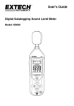
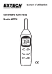
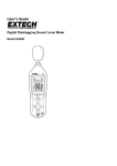
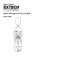
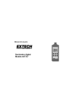
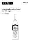
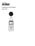
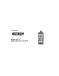
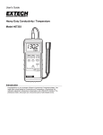
User's Guide
Digital Sound Level Meter
Model 407738
With Memory
Introduction
Congratulations on your purchase of the Extech 407738 Digital Sound Level Meter.
The 407738 measures and displays sound pressure levels in dB (decibels) from 26 to
130dB in six measurement ranges. The microphone can be removed and remotely
stationed for convenience. In addition to the LCD numerical displays, a bargraph is
included for quick and easy viewing of sound level changes. Features include selectable
Frequency Weighting (‘A’ and ‘C’), selectable Response Time (Fast and Slow), Max
Hold, and a 99 reading storage utility.
Careful use of this meter will provide years of reliable service.
Specifications
Applicable Standards
Measurement Functions
Primary Functions
Total range
Maximum level
Accuracy
Noise floor
Calibration signal
Range selections
Frequency range
Frequency weighting
Time weighting
Calibration
Display update rate
Data memory
Microphone
Display
Display features
Warning indicators
Analog Outputs
Power requirements
Operating conditions
Storage conditions
Dimensions
Weight
IEC61672-1: 2002 Class 2; IEC60651: 1979 Type 2; ANSI S1.4:1983 Type 2
Sound Pressure Level
Maximum Sound Level
Minimum Sound Level
26 to 130dB (32 to 130dB for ‘C’ weighted measurements)
130dB
± 1.5dB (under reference conditions)
‘A’ weighting: 26dB
‘C’ weighting: 32dB
94dB at 1kHz (sinusoidal)
26 to 80, 30 to 90, 40 to 100, 50 to 110, 60 to 120, 70 to 130
31.5 to 8000 Hz
‘A’ and ‘C’
Fast (125ms) and Slow (1 second) Response
Requires external calibrator (not included)
Bargraph display: 125ms; Numerical indication: 1 second
99 data sets (max.) for sound level (L), maximum sound level (Lmax), and
minimum sound level (Lmin) can be stored with elapsed timer.
0.5” electret condensor
4-digit indication of sound level with 0.1dB resolution
Bargraph indication of sound level with 1dB resolution
Elapsed time; 100 hours maximum
Store and recall readings (99 data sets max.)
Over-range ‘OV’; Under-range: ‘Un’
AC: 0.707Vrms full scale; Output impedance: 5KΩ
DC: 10mV/1dB; Output impedance: 5KΩ
9V Battery; Battery life approx. 50 hours
14 to 122oF (-10 to 50oC); 90% relative humidity max.
14 to 132oF (-10 to 60oC); 90% relative humidity max.
10.4 x 2.7 x 1.1” (264 x 68 x 27mm)
9.2 oz. (260g)
Support line (781) 890-7440
Technical support: Extension 200; E-mail: [email protected]
Repair & Returns: Extension 210; E-mail: [email protected]
Product specifications subject to change without notice
For the latest version of this User’s Guide, Software updates, and other
up-to-the-minute product information, visit our website: www.extech.com
2
Model 407738 Version 2.2 September 2005
Meter Description
1. Microphone: Electret condenser
2. Microphone collar: unscrew to remove microphone
3. LCD Display
4. Push-buttons:
•
Power button
•
A,C buttons: Sets the frequency weighting
•
FAST, SLOW buttons: Sets the response time
•
MAX button: Selects MAX, MIN or current measurement; also used to test the
FAST/SLOW characteristics. Press and hold the MAX button for 5 seconds
(MAX will flash on the LCD); press again to exit. For specifics, refer to relevant
sections in this manual.
•
MEM button: Press to store a data set in memory
•
READ button: Press to read the stored data sets
•
Up and Down Arrow buttons: Used to select measurement ranges; also used to
scroll through the stored data sets in the MEM (memory) mode.
5. CAL potentiometer: For calibration. Optional calibrator required.
6. External 9VDC power adaptor
7. DC/AC analog output: Retransmission of sound level measurement for chart recorder
or other datalogger
8. Tripod Mount
9. Battery compartment
1
2
3
4
With Memory
3
5
6
8
7
9
Model 407738 Version 2.2 September 2005
Display Description
3 4
1
5 6 7
00
2
19
8
Un Un
L0
180
Ov Ov
18.8.8
min
max
18
17
1dB
16
00
15
FAST SLOW
88:88:88
9 10
11
1.
Sound Level Range
2.
Bargraph indication
3.
Under-range indicator for current reading
4.
Under-range indicator for reading in memory
5.
Frequency weighting
6.
Over-range indicator for reading in memory
7.
Over-range indicator for current reading
8.
Battery status indicator
9.
FAST response time setting
FULL
MR
12 13 14
10. SLOW response time setting
11. Elapsed time indicator (100 hours max.)
12. Memory FULL indicator
13. Memory indicator
14. READ memory indicator
15. Address for stored reading
16. Sound level unit of measure (decibel)
17. Maximum sound level reading
18. Minimum sound level reading
19. Sound pressure level
4
Model 407738 Version 2.2 September 2005
Power Supply
The meter can be powered by one 9V battery or by the specified optional AC power
adaptor. Before inserting or replacing the battery and before connecting the AC adaptor,
be sure to turn off the meter.
Battery Installation
Remove the battery compartment cover (lower back of the meter) and install or replace the
9V battery.
Fully charged
Battery Capacity Indicator
The battery status indicator on the meter’s display (see diagram)
informs the user of the battery’s condition. The number of segments in
the display icon decreases as the battery weakens. When all segments
switch off and the icon flashes, the meter is about to lose power.
AC Voltage Adaptor
Partially charged
Replace battery
Insert the AC adaptor into the DC 9V jack on the side of the meter.
Connect the other end of the adaptor to an AC source. With a battery
installed and the AC adaptor in use, the AC adaptor has priority.
Measurements
1. Turn the meter ON by pressing the
button. The default settings are: ‘A’ frequency
response; ‘FAST’ response time; and 70 to 130dB range
2. Select the frequency weighting ‘A’ or ‘C” as desired using the ‘A’ or the ‘C’ buttons.
Typical sound level measurements use ‘A’ weighting.
3. Press the ‘FAST’ or ‘SLOW’ button to select the desired response time. Normally the
‘SLOW’ setting is used.
4. Use the up and down buttons to select the appropriate range. The range is shown at the
top left corner (low end of range) and top right corner (high end of range) of the LCD.
Use a range that puts the sound level reading in the center of the bargraph. If the OV
(over-range) or UN (under-range) icons appear with dashes on the main display area,
select a new range. Refer to the Specifications page for the list of available ranges.
5. The numeric and bargraph displays indicate the sound level measurement. The
numerical reading updates every second while the bargraph updates every 125ms.
MAX / MIN Operation
The Model 407738 stores the highest (MAX) and lowest (MIN) readings in its memory. The
stored MAX and MIN values are continually updated as new MAX and MIN values are
encountered. The user can recall these stored readings using the MAX button as
described in the steps below. Before starting, select an appropriate range as described
previously, otherwise the stored MIN/MAX readings may indicate all dashes (out of range).
1. Press the MAX button and the MAX icon will appear on the LCD. The reading shown is
the highest reading encountered since the meter was last reset. Note that the elapsed
timer display shows the time at which the MAX reading was recorded.
2. Press the MAX button again. The MIN icon will appear on the LCD and the reading
shown represents the lowest reading encountered since the meter’s memory was last
reset. The elapsed timer display shows the time at which the MIN reading was recorded.
3. Press the MAX button again to exit the MAX / MIN display mode (the MAX and MIN
display icons switch off when this mode is exited).
4. To clear the MAX / MIN memory, simply press the up or down arrow to change range.
Note that the elapsed timer starts when the meter is switched ON and continues running
until the meter is shut off or until 100 hours is reached.
5
Model 407738 Version 2.2 September 2005
Measurement Considerations
1. Wind blowing across the microphone increases the noise measurement. Use the
supplied windscreen to cover the microphone when applicable.
2. Calibrate the instrument before each use if possible. Especially if the meter has not
been used for a long period of time.
3. Do not store or operate the instrument in areas of high temperature or humidity.
4. Keep meter and microphone dry.
5. Avoid severe vibration. Protect the meter from impact. Do not drop it. Transport the
meter in the supplied case.
6. Remove the battery when the meter is to be stored for long periods of time.
Notes on ‘A’ and ‘C’ Frequency Weighting
Use the ‘A’ and ‘C’ buttons to select ‘A’ or ‘C’ frequency weighting. With ‘A’ weighting
selected, the frequency response of the meter is similar to the response of the human ear.
‘A’ weighting is commonly used for environmental or hearing conservation programs such
as OSHA regulatory testing and noise ordinance law enforcement. ‘C’ weighting is a much
flatter response and is suitable for the sound level analysis of machines, engines, etc.
Most noise measurements are performed using 'A' Weighting and SLOW Response.
Notes on ‘FAST’ and ‘SLOW’ Response Time
Use the FAST and SLOW buttons to select a FAST (125 ms) or a SLOW (1 second)
response time. Select FAST to capture noise peaks and noises that occur very quickly.
Select the SLOW response to monitor a sound source that has a consistent noise level or
to average quickly changing levels. Select SLOW response for most applications.
Storing and Recalling Readings
Storing readings
Press the MEM button momentarily to store a reading. The meter will store the current
measurement, the current MAX & MIN values, and the elapsed time. The display icon ‘M’
will appear briefly when the MEM button is pressed along with the storage location (01
through 99). The ‘FULL’ display icon will appear when the meter’s internal memory has
reached capacity (99 readings).
Recalling readings
1. Press the READ button to enter the recall mode (the ‘R’ display icon will appear on the
LCD).
2. Use the arrow keys to scroll through the stored reading list. The memory location
number displays for each stored reading (01 through 99).
3. Use the MAX button to scroll through the MAX, MIN, and Elapsed Time data stored at
the current location.
4. Press the READ button again to exit the recall mode.
Clearing Stored readings
1.
2.
3.
4.
Turn the meter OFF.
Press and hold the MEM button while turning the meter ON.
When the ‘CLr’ (clear) display icon appears, release the MEM button.
All of the readings that were stored in memory are now erased.
6
Model 407738 Version 2.2 September 2005
Analog Outputs
The Model 407738 is equipped with an analog output feature.
The analog output jack is located on the meter’s right side
(see ‘Description’ section of manual for location). AC and DC
analog signals are available from the provided jack (refer to
the 3.5mm stereo phono plug diagram for wiring).
AC Output
DC Output
Common
AC analog output specifications
The AC output is a retransmitted representation of the meter’s measurement (note that
the output factors in the meter’s frequency weighting selection ‘A’ or ‘C’).
• Output voltage: 0.707Vrms at full scale of the selected range.
• Output impedance: 5KΩ approx.
DC analog output specifications
The DC output is level-converted and generated by rms detection and logarithmic
compression. The signal reflects the frequency weighting selected (‘A’ or ‘C’).
• Output voltage: 10mV (±1mV) per displayed dB.
• Output impedance: 5KΩ approx.
Calibration
To calibrate the 407738, an external calibrator (such as the Extech 407744 or the Extech
407766) is required in addition to a small screw-driver.
1. Turn the meter ON
2.
Put the meter in the ‘A’ weighting mode
3.
Put the meter in the ‘SLOW’ response mode
4.
Place the 407738 microphone into the calibrator.
5.
Turn the calibrator ON.
6.
Put the meter in the 70 to 130dB range
7.
Adjust the meter’s CAL potentiometer so that the meter’s display matches the
output of the calibrator.
Safety
Read the following safety information carefully before attempting to operate or
service the meter. Use the meter only as specified in this manual; otherwise, the
protection provided by the meter may be impaired.
Environmental Conditions
Altitude up to 2000 meters; Relative Humidity: 90% max.
Maintenance and Cleaning
Servicing not covered in this manual should be performed by qualified personnel.
Periodically wipe the case with a dry cloth. Do not use abrasives or solvents.
7
Model 407738 Version 2.2 September 2005
Typical A-Weighted Sound Levels
dBA
140
50HP Siren (100')
Jet takeoff (200')
Riveting machine
130
120
110
Chain saw
100
Subway (20')
90
Pneumatic drill (50')
80
Vacuum cleaner (10')
70
Large store
60
Small office
50
Night residential area
40
Whisper (5'0)
30
Boiler room
Freight train (100')
Speech (1')
Large Office
Residence
Sound studio
20
10
Threshold of hearing
0
Warranty
EXTECH INSTRUMENTS CORPORATION warrants this instrument to be free of defects in parts and
workmanship for one year from date of shipment (a six month limited warranty applies to sensors and cables).
If it should become necessary to return the instrument for service during or beyond the warranty period,
contact the Customer Service Department at (781) 890-7440 ext. 210 for authorization or visit our website
www.extech.com for contact information. A Return Authorization (RA) number must be issued before any
product is returned to Extech. The sender is responsible for shipping charges, freight, insurance and proper
packaging to prevent damage in transit. This warranty does not apply to defects resulting from action of the
user such as misuse, improper wiring, operation outside of specification, improper maintenance or repair, or
unauthorized modification. Extech specifically disclaims any implied warranties or merchantability or fitness for
a specific purpose and will not be liable for any direct, indirect, incidental or consequential damages. Extech's
total liability is limited to repair or replacement of the product. The warranty set forth above is inclusive and no
other warranty, whether written or oral, is expressed or implied.
Calibration and Repair Services
Extech offers repair and calibration services for the products we sell. Extech also
provides NIST certification for most products. Call the Customer Service Department for
information on calibration services available for this product. Extech recommends that
annual calibrations be performed to verify meter performance and accuracy.
Copyright © 2005 Extech Instruments Corporation
All rights reserved including the right of reproduction in whole or in part in any form.
8
Model 407738 Version 2.2 September 2005