1
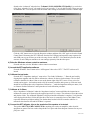
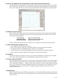
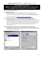
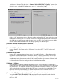
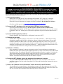
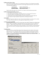
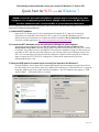
Skip directly to the section that covers your version of Windows (7, Vista or XP)
Quick Start for WT3 (v2.0) on Windows 7
*** VERY IMPORTANT SAFETY NOTE ***
NEVER connect the test leads of the WT3 to a speaker that is connected to any other
equipment or to an equipment ground! Severe damage could occur to the WT3 unit or to
the other equipment! Only connect the WT3 to an unconnected loudspeaker.
Here are step-by-step instructions to get you going quickly. Later, as you wish to learn more about using WT3, you can refer to the
built-in User’s Guide found under the Help menu.
1) Install the WT3 software.
Insert the WT3 CD into your PC’s drive and allow the file named "WT3_setup.exe" to auto-play.
(Alternately you can double-click on the file "WT3_setup.exe" to start the installation process.)
Follow the on-screen instructions to complete the software installation. Do not launch the software yet.
Check for available upgrades at: http://www.daytonaudio.com/wt3updates.html
2) Connect the WT3 hardware unit to any convenient USB port on your computer.
Upon being connected and powering up the unit requires a full 90 seconds to stabilize before
measurements can be made. After this plug-in delay, impedance measurements take only a few seconds
to complete. Any USB port can be used with WT3 but each port remembers its setup. For this reason you
can either use WT3 with one particular USB port or you can setup each of your USB ports in turn to use
WT3. It is not a bad idea to just plug the unit into each port in sequence and set each port for 2-channel
input as required for WT3. The 90 sec. settling time is related to the requirement for precision
measurements down to 1 Hz.
3) Setup the USB port for 2-channel input and verify the input level for Windows 7.
From the Windows “Start” button select Control Panel/Sound. Once the Sound control panel opens select
the “Recording” tab as seen below (left). Next, double-click on the device “USB Audio Device” to open the
Properties window seen below (right). Note that on Windows 7 the WT3 hardware may appear as "USB
Audio CODEC", "USB Audio Device" or similar.
Revised: 4Feb11
Switch to the “Advanced” tab and select “2 channel, 16 bit, 44100 Hz (CD Quality)” as seen below
(left). Next, select the “Levels” tab set the level is set to exactly “1” as seen below (right). These two steps
are critical as WT3 will not operate with the default audio settings of maximum level and 1 channel input.
Click the “OK” button once to close the Properties window and then click “OK” again to close the Sound
Control Panel. Disconnect the WT3 USB unit from the first USB port and repeat this setup sequence for
each USB port on your PC that you wish to be setup for use with WT3. You should only need to do this
one time as each USB port remembers its own settings separately from the other ports.
4) Raise the Windows volume control to maximum.
From the task bar, raise the Windows volume control to maximum.
5) Launch the WT3 application software.
From the Windows “Start” button select “All Programs” then select “WT3”. The WT3 software will
launch.
6) Calibrate the test leads.
From the WT3 “Impedance Analyzer” menu select “Test Leads Calibration…”. Short the test leads by
clipping them together and click OK to calibrate the software for the test lead resistance. The test lead
resistance should be less than 1 Ohm as seen at the bottom right of the WT3 screen. If not, wait a few
seconds and try again…the hardware needs a full 90 seconds to stabilize after power up. If the test leads
should fail to calibrate then select “Impedance Calibration…” under the Impedance Analyzer menu, click
on “Restore Default Calibration” and repeat the test leads calibration procedure.
7) Calibrate at 1k Ohms.
Select “Impedance Calibration” under the “Impedance Analyzer” menu and follow the instructions to
calibrate the system at 1k Ohms using the supplied precision 1% resistor. The software will test the resistor
and plot the results. The calibrated impedance is displayed and the calibration is complete. Verify that the
value displayed in the R(e) field at the right side of the screen is reasonably close to 1000 Ohms. If not,
repeat the calibration procedure making sure the hardware has had a full 90 seconds to stabilize. A
measured value between 950 and 1050 Ohms is expected.
8) Connect the WT3 alligator clips to the terminals of the speaker to be tested.
The speaker MUST NOT BE CONNECTED to anything else such as an amplifier, other electrical
equipment or ground. For best results clamp the driver in place and allow adequate clearance for any rear
pole piece vents.
Revised: 4Feb11
9) Click on the "Measure Free Air Parameters" button at the left of the WT3 window.
You should hear the sweep and then see the impedance response of the driver appear on the screen similar
to the screen below. The speaker’s free air parameters are displayed in the Parameters Bar at the right side
of the screen. At the left side you can set the upper impedance limit and the high and low frequency limits.
10) Measure the driver’s V(as).
Once you have measured the speaker’s free air parameters the "Measure V(as)" button becomes enabled.
Select one of the three methods to measure the V(as) at the upper right side of the WT3 screen. The three
V(as) measurement methods are:
Test Box Method
Added Mass Method
Specified SPL Method
- requires a suitable test box
- requires you to add a known mass
- requires the SPL be known
Enter the required data and then press the “Measure V(as)” button to start the measurement procedure.
11) After measuring the speaker you can:
• Save the data to one of 20 project memories.
• Save a WT3 project file (file type .wt3) which includes your test setup and all 20 memories.
• Export the parameters and impedance data in either .txt or .zma formats.
• Overlay plots of various measured impedances from the 20 memories for detailed comparison.
• Print a report showing the impedance and parameters of the displayed memories.
12) Quit WT3.
Quit the WT3 application software by using “Ctrl+Q” from the keyboard or by selecting “Exit” under the
“File” menu. On exit the software saves your application settings for the next session.
13) Future sessions with WT3.
In the future when you want to use WT3 you only need to connect the WT3 hardware unit, raise the master
volume and then launch the WT3 software. If you happen to launch the software first you will then need to
select “Audio Device Selection…” under the “Edit” menu so that WT3 can scan for the hardware and select
it for use. The software will retain its calibration from session to session but it is still a good idea to verify
the calibration at the start of each session by sweeping the supplied calibration resistor or some other
resistor of known value.
Troubleshooting
If there is a problem, review the USB port setup in Step 3. Also, remember that the hardware unit requires a
full 90 seconds to stabilize after power up. During this time the sweep may not be heard and measurements
will not be valid.
Revised: 4Feb11
Quick Start for WT3 (v2.0) on Windows Vista
*** VERY IMPORTANT SAFETY NOTE ***
NEVER connect the test leads of the WT3 to a speaker that is connected to any other
equipment or to an equipment ground! Severe damage could occur to the WT3 unit or to
the other equipment! Only connect the WT3 to an unconnected loudspeaker.
Here are step-by-step instructions to get you going quickly. Later, as you wish to learn more about using WT3, you can refer to the
built-in User’s Guide found under the Help menu.
1) Install the WT3 Software.
Insert the WT3 CD into your PC’s drive and allow the file named "WT3_setup.exe" to auto-play.
(Alternately you can double-click on the file "WT3_setup.exe" to start the installation process.)
Follow the on-screen instructions to complete the software installation. Do not launch the software yet.
Check for available upgrades at: http://www.daytonaudio.com/wt3updates.html
2) Connect the WT3 hardware unit to any convenient USB port on your computer.
Upon being connected and powering up the unit requires a full 90 seconds to stabilize before
measurements can be made. After this plug-in delay, impedance measurements take only a few seconds
to complete. Any USB port can be used with WT3 but each port remembers its setup. For this reason you
can either use WT3 with one particular USB port or you can setup each of your USB ports in turn to use
WT3. It is not a bad idea to just plug the unit into each port in sequence and set each port for 2-channel
input as required for WT3. The 90 sec. settling time is related to the requirement for precision
measurements down to 1 Hz.
3) Setup the USB port for 2-channel input and verify the input level for Windows Vista.
From the Windows “Start” button select Control Panel/Sound. Once the Sound control panel opens select
the “Recording” tab as seen below (left). Next, double-click on the device “USB Audio CODEC” to open
the Properties window seen below (right).
Revised: 4Feb11
Switch to the “Advanced” tab and select “2 channel, 16 bit, 44100 Hz (CD Quality)” as seen below
(left). This step is critical as WT3 will not operate with the default audio setting of 1 channel input. Next,
select the “Levels” tab and verify that the level is set to “25” as seen below (right).
Click the “OK” button once to close the Properties window and then click “OK” again to close the Sound
Control Panel. Disconnect the WT3 USB unit from the first USB port and repeat this setup sequence for
each USB port on your PC that you wish to be setup for use with WT3. You should only need to do this
one time as each USB port remembers its own settings separately from the other ports.
4) Raise the Windows volume control to maximum.
From the task bar, raise the Windows volume control to maximum.
5) Launch the WT3 application software.
From the Windows “Start” button select “All Programs” then select “WT3”. The WT3 software will
launch.
6) Calibrate the test leads.
From the WT3 “Impedance Analyzer” menu select “Test Leads Calibration…”. Short the test leads by
clipping them together and click OK to calibrate the software for the test lead resistance. The test lead
resistance should be less than 1 Ohm as seen at the bottom right of the WT3 screen. If not, wait a few
seconds and try again…the hardware needs a full 90 seconds to stabilize after power up. If the test leads
should fail to calibrate then select “Impedance Calibration…” under the Impedance Analyzer menu, click
on “Restore Default Calibration” and repeat the test leads calibration procedure.
7) Calibrate at 1k Ohms.
Select “Impedance Calibration” under the “Impedance Analyzer” menu and follow the instructions to
calibrate the system at 1k Ohms using the supplied precision 1% resistor. The software will test the resistor
and plot the results. The calibrated impedance is displayed and the calibration is complete. Verify that the
value displayed in the R(e) field at the right side of the screen is reasonably close to 1000 Ohms. If not,
repeat the calibration procedure making sure the hardware has had a full 90 seconds to stabilize. A
measured value between 950 and 1050 Ohms is expected.
8) Connect the WT3 alligator clips to the terminals of the speaker to be tested.
The speaker MUST NOT BE CONNECTED to anything else such as an amplifier, other electrical
equipment or ground. For best results clamp the driver in place and allow adequate clearance for any rear
pole piece vents.
Revised: 4Feb11
9) Click on the "Measure Free Air Parameters" button at the left of the WT3 window.
You should hear the sweep and then see the impedance response of the driver appear on the screen similar
to the screen below. The speaker’s free air parameters are displayed in the Parameters Bar at the right side
of the screen. At the left side you can set the upper impedance limit and the high and low frequency limits.
10) Measure the driver’s V(as).
Once you have measured the speaker’s free air parameters the "Measure V(as)" button becomes enabled.
Select one of the three methods to measure the V(as) at the upper right side of the WT3 screen. The three
V(as) measurement methods are:
Test Box Method
Added Mass Method
Specified SPL Method
- requires a suitable test box
- requires you to add a known mass
- requires the SPL be known
Enter the required data and then press the “Measure V(as)” button to start the measurement procedure.
11) After measuring the speaker you can:
• Save the data to one of 20 project memories.
• Save a WT3 project file (file type .wt3) which includes your test setup and all 20 memories.
• Export the parameters and impedance data in either .txt or .zma formats.
• Overlay plots of various measured impedances from the 20 memories for detailed comparison.
• Print a report showing the impedance and parameters of the displayed memories.
12) Quit WT3.
Quit the WT3 application software by using “Ctrl+Q” from the keyboard or by selecting “Exit” under the
“File” menu. On exit the software saves your application settings for the next session.
13) Future sessions with WT3.
In the future when you want to use WT3 you only need to connect the WT3 hardware unit, raise the master
volume and then launch the WT3 software. If you happen to launch the software first you will then need to
select “Audio Device Selection…” under the “Edit” menu so that WT3 can scan for the hardware and select
it for use. The software will retain its calibration from session to session but it is still a good idea to verify
the calibration at the start of each session by sweeping the supplied calibration resistor or some other
resistor of known value.
Troubleshooting
If there is a problem, review the USB port setup in Step 3. Also, remember that the hardware unit requires a
full 90 seconds to stabilize after power up. During this time the sweep may not be heard and measurements
will not be valid.
Revised: 4Feb11
Quick Start for WT3 (v2.0) on Windows XP
*** VERY IMPORTANT SAFETY NOTE ***
NEVER connect the test leads of the WT3 to a speaker that is connected to any other
equipment or to an equipment ground! Severe damage could occur to the WT3 unit or to
the other equipment! Only connect the WT3 to an unconnected loudspeaker.
Here are step-by-step instructions to get you going quickly. Later, as you wish to learn more about using WT3, you can refer to the
built-in User’s Guide found under the Help menu.
1) Install the WT3 software.
Insert the WT3 CD into your PC’s drive and allow the file named "WT3_setup.exe" to auto-play.
(Alternately you can double-click on the file "WT3_setup.exe" to start the installation process.)
Follow the on-screen instructions to complete the software installation. Do not launch the software.
Check for available upgrades at: http://www.daytonaudio.com/wt3updates.html
2) Connect the WT3 hardware unit to any convenient USB port on your computer.
Upon being connected and powering up the unit requires a full 90 seconds to stabilize before
measurements can be made. After this plug-in delay, impedance measurements take only a few seconds
to complete. The 90 sec. settling time is related to the requirement for precision measurements down to 1
Hz.
3) Launch the WT3 application software.
From the Windows “Start” button select “All Programs” then select “WT3”.
4) Calibrate the test leads.
From the WT3 “Impedance Analyzer” menu select “Test Leads Calibration…”. Short the test leads by
clipping them together and click OK to calibrate the software for the test lead resistance. The test lead
resistance should be less than 1 Ohm as seen at the bottom right of the WT3 screen. If not, wait a few
seconds and try again…the hardware needs a full 90 seconds to stabilize after power up. If the test leads
should fail to calibrate then select “Impedance Calibration…” under the Impedance Analyzer menu, click
on “Restore Default Calibration” and repeat the test leads calibration procedure.
5) Calibrate at 1k Ohms.
Select “Impedance Calibration” under the “Impedance Analyzer” menu and follow the instructions to
calibrate the system at 1k Ohms using the supplied precision 1% resistor. The software will test the resistor
and plot the results. The calibrated impedance is displayed and the calibration is complete. Verify that the
value displayed in the R(e) field at the lower right side of the WT3 screen is reasonably close to 1000
Ohms. If not, repeat the calibration procedure making sure the hardware has had a full 90 seconds to
stabilize. A measured value between 950 and 1050 Ohms is expected.
6) Connect the WT3 alligator clips to the terminals of the speaker to be tested.
The speaker MUST NOT BE CONNECTED to anything else such as an amplifier, other electrical
equipment or ground. For best results clamp the driver in place and allow adequate clearance for any rear
pole piece vents.
7) Click on the "Measure Free Air Parameters" button at the left of the WT3 window.
You should hear the sweep and then see the impedance response of the driver appear on the screen. The
speaker’s free air parameters are displayed in the Parameters Bar at the right side of the screen. At the left
side you can set the upper impedance limit and the high and low frequency limits.
Revised: 4Feb11
8) Measure the driver’s V(as).
Once you have measured the speaker’s free air parameters the "Measure V(as)" button becomes enabled.
Select one of the three methods to measure the V(as) at the upper right side of the WT3 screen. The three
V(as) measurement methods are:
Test Box Method
Added Mass Method
Specified SPL Method
- requires a suitable test box
- requires you to add a known mass
- requires the SPL be known
Enter the required data and press the “Measure V(as)” button to start the measurement procedure.
9) After measuring the speaker you can:
• Save the data to one of 20 project memories.
• Save a WT3 project file (file type .wt3) which includes your test setup and all 20 memories.
• Export the parameters and impedance data in either .txt or .zma formats.
• Overlay plots of various measured impedances from the 20 memories for detailed comparison.
• Print a report showing the impedance and parameters of the displayed memories.
10) Quit WT3.
Quit the WT3 application software by using “Ctrl+Q” from the keyboard or by selecting “Exit” under the
“File” menu. On exit the software saves your application settings for the next session.
11) Future sessions with WT3.
In the future when you want to use WT3 you only need to connect the WT3 hardware unit and then launch
the WT3 software. If you happen to launch the software first you will need to first select “Audio Device
Selection…” under the “Edit” menu so that WT3 can scan for the hardware and select it for use. The
software will retain its calibration from session to session but it is still a good idea to verify the calibration
at the start of each session by sweeping the supplied calibration resistor or some other resistor of known
value.
Troubleshooting
If there is a problem, open the Windows Sound Control Panel and select the Audio tab. Then select the
Default device to be the “USB Audio CODEC” (this is the WT3 hardware) as shown below at the left.
Click on “Volume…” to open the mixer shown below at the right. Make sure the “Speaker” and “Wave”
volumes are set to maximum and that the corresponding balance controls are set to center. Once the
Volumes are set correctly, the Default device does not have to remain set to the “USB Audio CODEC” and
can be set to another device if necessary.
Revised: 4Feb11