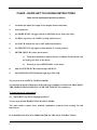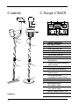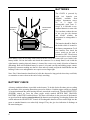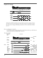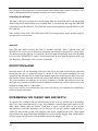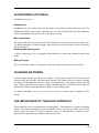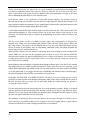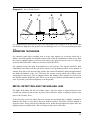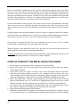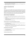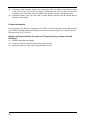
1
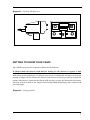
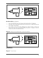
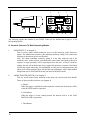
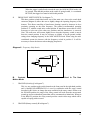
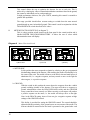
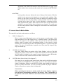
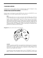
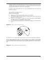
OPERATING INSTRUCTIONS
1
CS4ZX - RAPID GET YOU GOING INSTRUCTIONS
Look for the highlighted pre-set positions
1.
Assemble and adjust for length (Twist surplus lead around stem).
2.
Insert batteries.
3.
Set MODE SELECT (trigger switch) to MOTION (away from your body).
4.
Set DISC (top left) to ALL METAL (fully anticlockwise).
5.
Set NOTCH (bottom far left) to OFF (fully anticlockwise).
6.
Set SENSITIVITY (top right) to white marker (3 o'clock position).
7.
METER SWITCH (centre, below meter)
a) Push down and hold to indicate battery condition. Good batteries will
be in the green area on the meter.
b)
Push up to select METER DISC on the meter.
8.
Push NOTCH SWITCH bottom left up to REJECT.
9.
Push GROUND SWITCH bottom right up to INLAND.
You are now in ALL METAL MOTION MODE.
You will find all metals within the search head range including iron and trash PROVIDING
THE SEARCH HEAD IS MOVING OVER THE TARGET (not stationary).
To ignore these low value metals:10. Adjust DISC (top left) to highlight position 5.
You are now in DISCRIMINATING MOTION MODE.
The other modes require more detailed explanation acquired from reading the full
instructions.
IF A PROBLEM IS ENCOUNTERED REFER TO THE FULL INSTRUCTIONS.
2
CONTENTS:
PAGE
INTRODUCTION
ASSEMBLY
BATTERIES
BATTERY CHECK
GETTING TO KNOW YOUR CS4ZX
CONTROLS
CHANGING MODES
OPERATING IN MOTION MODE
OPERATING IN NON MOTION MODE
DETECTION RANGE
DETERMINING THE TARGET SIZE AND DEPTH
ACCESSORIES (OPTIONAL)
CHARGING BATTERIES
THE IMPORTANCE OF THE RIGHT APPROACH
SWEEPING TECHNIQUE
METAL DETECTING AND THE ENGLISH LAW
CODE OF CONDUCT FOR METAL DETECTOR USERS
CARE OF YOUR DETECTOR
DETECTOR NOT OPERATING?
4
4
4
5
6
8
11
12
15
16
16
16
16
17
18
19
19
20
20
3
Controls
C-Scope CS4ZX
J
A
K
L
T
S
CS4ZX
M
N
O
P
Q
R
B
C
I
A
B
C
D
E
F
G
H
I
D
J
E
H
K
L
M
N
F
G
O
P
Q
R
Diagram 1
4
S
T
Battery Compartment
Din Plug & Socket
Upper Stem & Handle Grips
Stem Connecting Nut
Lower Stem
Search Head Lugs
Search Head Fastener
Cable
Frequency Select Switch
(Both Modes)
All Metal Mode/Discrimination
(Motion Mode)
Meter (Both Modes)
Power On/Off & Sensitivity
Notch Discrimination
(Motion Mode)
Notch Discrimination
Accept/Reject (Motion Mode)
Mode Select
Meter Function select
Beach/Inland Select
(Non Motion Mode)
Variable Ground Control
(Non Motion Mode)
Battery Charge Socket Cover
Headphone Socket Cover
INTRODUCTION
To protect your investment complete both sections of the enclosed guarantee card and return the
reply paid portion to C-Scope. This is particularly important in order to obtain the free
second year parts guarantee. Please retain the original packing box. In the event that your
detector should ever require to be serviced, this package will be most suitable for postal protection.
C-Scope detectors are recognised as the finest detectors available. They are designed with lasting
quality, high technology, and above all, value for money. The only way to realise this value is to
carefully study and understand this instruction manual. You will then be able to obtain all the
advantages designed into your detector. It is also strongly recommended that you experiment with
the detector's operation in air using various test samples, in order to learn to identify and understand
the detector's capabilities and responses. Always remember that becoming a good metal detectorist
is like becoming a good photographer or fisherman, that is, although it is an advantage to buy the
best equipment, having bought it, patience and hours of practice are needed to become proficient.
ASSEMBLY
Open the inner carton and remove the main housing assembly. Remove the search head and lower
stem from between the inner carton walls. Twist the plastic stem lock, located at the end of the upper
stem to allow the lower stem to be inserted. Turn the stem lock to lock it at the desired position.
Diagram 2 Battery Compartment
5
BATTERIES
CHARGER
HEADPHONE
SOCKET
SOCKET
The CS4ZX is powered by
eight AA batteries (not
supplied)
available
from
garages, department stores,
etc. or a single 12v
rechargeable pack from CScope. It is advisable to use
standard batteries to start with.
You can then evaluate the sort
of use you give the detector
and decide whether the
investment in rechargeables is
justified.
The batteries should be fitted in
the holder which is located in
BATTERY
COMPARTMENT
the battery compartment. To fit
new batteries first check the
power switch on the unit is
switched to OFF. Then loosen
the two captive screws located
in the battery cover (do not fully remove these from the cover) and remove the cover. Inside is the
battery holder. Lift out the holder and detach the connector if it is already fitted. Load it with the
eight batteries ensuring that each battery is inserted the correct way round, (direction of batteries
alternating). Roll each individual battery to ensure it is located correctly and making proper contact.
Replace the connector making sure that it is firm and well seated, and put the loaded holder into the
housing. Fit the cover and tighten the two captive screws finger tight.
Note: Zinc Carbon batteries should not be left in the detector for long periods where they could leak,
so remember to remove them at the end of a day's searching.
BATTERY CHECK
A battery condition indicator is provided on the detector. To do this for the first time prior to reading
the remainder of the operating instructions proceed as follows:- Push the trigger switch (see diagram
3) located underneath the main housing forward, towards the search head. Turn the SENSITIVITY
(POWER) control on. Press the centre toggle switch marked METER DISC GROUND,
BATTERY to BATTERY and hold down. The meter will indicate in the green area if the batteries
are good and in the red or central position if the batteries need replacing or recharging. Release the
switch and turn the SENSITIVITY control off. Rechargeable batteries will not read as high into the
green as standard batteries even when fully charged. They also give less indication of discharge on
the meter during use.
6
Diagram 3 Checking The Batteries
CS4ZX
HOLD
GETTING TO KNOW YOUR CS4ZX
The CS4ZX has two modes of operation, Motion and Non Motion.
In Motion mode the detector head must be moving for the detector to register a find.
Motion has the advantage of automatic ground cancellation and simplicity of operation. Non motion
mode allows greater performance in restricted areas such as in undergrowth and allows accurate pin
pointing of targets. In Non Motion the detector head need not be moving to indicate a target but
patience and practice is required to develop the skills necessary to enjoy the full benefit of this mode.
Selection of mode is made on the Trigger switch located behind the hand grip and is operated with
your index finger.
Diagram 4 Changing Modes
7
Motion
Non Motion
Hold
Tune/Retune
Push the switch forward to operate in MOTION mode, leave in the central position to operate
NON MOTION and pull back and release to RETUNE in NON MOTION and to recentralise the
meter.
You will see the control panel on the front of the detector has been grouped into boxes. The DISC
and NOTCH controls and the NOTCH switch are functional when the detector is in MOTION
mode only. The GROUND control and switch are functional in the NON MOTION mode. The
SENSITIVITY control is common to both modes. The function of each control is explained fully in
the section headed 'CONTROLS' (PAGE 8).
Find an area where the search head can be put, free from metal, including floor boards and
reinforced concrete, and try out the detector, i.e. on a table with search head facing upwards and
overhanging the edge.
Motion Mode (see diagram 5):
1.
2.
3.
4.
5.
6.
Switch NOTCH to the off position (fully anticlockwise).
Switch DISC to the all metal position (fully anticlockwise).
Hold the trigger switch in the retune position 1 in diagram 5 and turn the SENSITIVITY to
the large white segment, the detector should now be sitting quietly with the meter centralised.
Release the trigger switch and move it into its motion mode position 3 in diagram 6.
Now sweep a coin over the head, either side of the head will do, and the detector will give a
signal. Move the coin slowly across the head, the detector will still give a signal. Place the
coin on the head and the detector will be quiet or give a low volume tone all the time the coin
is stationary. This is how the MOTION mode operates.
Remove the coin and recentralise the meter if necessary by pulling the trigger switch towards
you and releasing (RETUNING), then pushing the switch away from you. The detector is
ready for use in MOTION mode.
Diagram 5 Settings For Motion Mode - All Metal Searching
8
ALL
METAL
CS4ZX
METER
DISC
2
1
OFF
Non Motion Mode (see diagram 6):
1.
2.
3.
Select NON MOTION mode on the trigger switch (central position 3 in diagram 6).
Now pass a coin over the head and notice how the detector gives a signal all the time the
coin is within a certain distance.
Your CS4ZX is built with the latest technology but it will be necessary to retune your
detector from time to time by momentarily flicking into postition 1 in diagram 6. This will
counteract any drift and recentralise the meter.
Diagram 6 Settings For Non Motion Mode - Meter Discrimination
REJECT
ALL
METAL
TARGET
CS4ZX
METER
DISC INLAND
3 1
OFF
CONTROLS
Diagram 7 Control Layout
9
J
K
L
I
CS4ZX
O
M
N
O
P
Q
R
The following explains the controls of your CS4ZX. When you are familiar turn to page 12-15 for
full operating details.
A. Controls Common To Both Operating Modes
i.
SENSITIVITY (L in diagram 7).
This is a rotary control which enables the user to set the sensitivity of the detector to
targets. The anticlockwise position is the minimum sensitivity setting. This control also
functions as the detector power on/off switch.
Note: The actual maximum sensitivity setting is at the fully clockwise end of the
sensitivity scale. At this position, a threshold tone can be heard and signals produced in
response to target proximity will be superimposed on this tone. At lower sensitivity
settings, the tone will be heard only when a target itself produces a response. Individuals
will set this control where they feel comfortable as some prefer a background tone and
others prefer silent operation. Most will find the best performance with a slight audible
background tone in NON MOTION and just silent in MOTION mode.
ii.
MODE TRIGGER SWITCH (O in diagram 7).
This is a switch located on the underside of the main case, just forward of the handle.
There are three possible positions (see diagram 4):
a. Motion.
When the trigger is pushed forward towards the search head, the detector will be
in the MOTION mode of operation.
b. Non Motion.
When the trigger is in the central position, the detector will be in the NON
MOTION mode of operation.
c. Tune/Retune.
10
When the trigger is pulled back towards the user, the NON MOTION mode will
be 'retuned'. Note that this position on the switch is 'spring loaded', i.e. to maintain
RETUNE, the trigger lever must be held in this position.
iii.
FREQUENCY SHIFT SWITCH (I in diagram 7).
This three position switch found on the rear of the main case, close to the search head
connector (diagram 8) allows the user to slightly change the operating frequency of the
detector. This allows cancelling of interference (beating) caused by detectors in close
proximity operating on the same frequency. The normal (recommended) operating
position is '2', with the switch in the central position. If interference occurs then it will be
necessary to select one of the other two positions until the interference is removed.
Note: The audio tone will become slightly lower when the frequency switch is moved
from the central position. It may be necessary to slightly re-set the ground exclude
setting when changing frequency in the NON MOTION mode. When using the mini
searchhead operate the detector with the frequency switch in position 2. It will be
necessary to retune the detector when changing frequencies.
Diagram 8 Frequency Shift Switch
1
2
3
B.
Controls
Motion Mode
Used In The Non
i.
GROUND (Switch) (Q in diagram 7).
This is a two position toggle switch located on the front panel in the right hand position
and is labelled INLAND/BEACH. It is used in conjunction with the rotary control
described in B.ii. below to change the range available on the rotary control. When set to
the INLAND position, the range of the rotary control will work from the most neutral
ground up to more mineralised ground that will be encountered on inland sites. When set
to the BEACH position, the rotary control provides a much wider range which will be
capable of coping with wet sand.
ii.
GROUND (Rotary control) (R in diagram 7).
11
This control allows the user to optimise the detector for use on each site. This is
achieved by reducing the effect of natural mineralisation sometimes found in the ground,
but it must be individually set for each ground type.
In high performance detectors, like your CS4ZX, mastering this control is essential to
gain the full capabilities.
The range provided should allow accurate setting to exclude from the most neutral
ground through to more 'mineralised' ground. This control is used in conjunction with the
INLAND/BEACH switch described in B.i. above.
iii.
METER FUNCTION SWITCH (P in diagram 7).
This is a three position switch located on the front panel in the central position and is
labelled METER DISC/GROUND/BATTERY. It allows the user to select which
information the meter will display.
Diagram 9 Meter Function Switch
CS4ZX
CS4ZX
CS4ZX
a) Meter Disc
b) Ground
c) Battery
a. METER DISC
In this position the meter responds to signals by referring to the pre-programmed
discriminating channel of the detector. After retuning the needle will normally be in
the centre of the scale. The needle will move to the left for iron and small pieces of
aluminium foil, i.e. a negative response, and stay central or move to the right for
other targets, i.e. a positive response.
b. GROUND
With the switch in this position the meter shows the responses from the variable
ground excluding channel of the detector. The meter will show no response to
ground mineralisation when the BEACH/INLAND switch and the GROUND
rotary control have been correctly set. When correctly set, all targets will produce
a positive response on the meter, i.e. the needle will always move to the right.
Note: in the BEACH setting, items of iron can give a negative response at high
settings of the GROUND control.
This facility is provided for setting the GROUND control. The control should be
adjusted until the proximity of the ground causes no movement of the needle. The
detector should be retuned before the head is presented to the ground after each
12
adjustment of the GROUND control in NON MOTION mode (see page 15 for
further details). Once correctly set this control can be returned to METER DISC
(a).
c. BATTERY
In this position, the meter indicates the state of charge of the batteries. When the
needle is in the green area, the batteries are in a good usable condition. If the
needle is in the centre or to the left of centre, the batteries are exhausted. It must
be stressed that when the charge falls to a totally unusable level then the needle
will settle in the centre of the scale. Use this indication in conjunction with the
audio signal from the speaker. If the needle is in the centre or to the left of centre
and there is no sound emitted, then the batteries are exhausted. The switch must
be held in this position to obtain a reading and it will return to the central position
when released.
C. Controls Used In Motion Mode.
The controls for use in the motion mode are as follows:
i.
DISC (J in diagram 7).
This is a rotary control allowing the user to set the response to certain targets. At the
fully anticlockwise end of the control there is a switched position. In this position the
detector will respond to ALL METAL. When only just moved from the switched
position, small iron targets will be discriminated against. As the control is moved
clockwise, more and more targets will be discriminated against (i.e. ignored on the audio
output). The order of discrimination is typically: iron, silver paper, 5p, ring pull, 20p,
10p, screw bottle cap.
ii.
NOTCH (M in diagram 7).
This rotary control allows the position of the 'Notch Window' to be set. The fully
anticlockwise position of the control is a switch (NOTCH OFF) and in this position the
NOTCH facility is disabled. As the control is moved clockwise, targets fall into the
window in the same order as that described in the DISC control above.
iii.
NOTCH (Mode Select Switch) (N in diagram 7).
This control is a two position switch located on the front panel in the left hand position
and is labelled ACCEPT/REJECT. The switch only has an effect while the NOTCH
control is switched on. When set to the REJECT position, targets within the window are
ignored or REJECTED. When set to the ACCEPT position only targets within the
window will produce a response from the loudspeaker.
General note:
When operating the detector in motion mode, the meter displays responses
from the meter discriminating channel of the detector. This is independent of
the position of the switch. Thus meter movements will be as described in section
B.iii.a.
13
CHANGING MODES
Switching from one mode to another is done by operating the trigger switch (O in diagram 7). Away
from the body to select MOTION and central to select NON MOTION.
OPERATING IN MOTION MODE
Push the trigger switch forward to select MOTION mode and turn the SENSITIVITY to the
highlighted area. Your CS4ZX, in MOTION mode, is now ready to use.
DISC
Discrimination allows the user to ignore certain metals whilst still finding others. DISC does
not allow individual metals to be ignored but rather a range. In the ALL METAL position
nothing is ignored. Turning the DISC control on at its lowest setting, the detector ignores
small iron objects but still detects the more valuable metals. Increasing the setting still further
and the detector will also ignore aluminium foil. Beyond this setting some valuable items will
begin to be rejected. Operating at a disc setting of ten rejects silver and nickel coins. A
recommended setting of five is highlighted at which iron and small pieces of aluminium foil are
ignored but most valuable items are still detected.
Diagram 10 Effect of Discriminate Control Position
CIGARETTE
PACKET
MILK
BOTTLE TOP
5p COIN
RING PULL
HORSESHOE
NAIL
£1 COIN
NOTCH
NOTCH is a variation of the DISC control which allows individual targets to be ignored, or
with the REJECT/ACCEPT switch in ACCEPT, detected and all others ignored. NOTCH
should only be used where specific items such as ring pulls are causing a nuisance as the
response to some valuable items is affected.
To set the detector to ignore ring pulls first make sure the ACCEPT/REJECT switch is set to
REJECT and DISC is in ALL METAL (off). Sweep the ring pull across the head whilst
14
adjusting the REJECT NOTCH control slowly. Repeat this until no sound is emitted. The
NOTCH cannot work on the deepest targets so to eliminate the response from ring pulls
totally then the SENSITIVITY must also be reduced slightly.
NOTCH ACCEPT works in the same way except a small band of targets are detected and
all others are ignored.
Now set DISC at 5 to ignore iron, etc.
Please note the following:
i)
ii)
iii)
iv)
Always set the NOTCH with the DISC control in ALL METAL.
The position at which objects are notched out is not exactly the same as the position at
which they are ignored on DISC.
Which ever is set highest of DISC and NOTCH has authority, thus NOTCH
ACCEPT will not work if the DISC setting is higher.
If necessary accurate pinpointing can be achieved by changing to the NON MOTION
mode.
Diagram 11 Effect of Notch Control Position
£1 COIN
RING PULL
The NOTCH is now set and the DISC control can now be used to achieve the desired combination.
It is the skilful combination of these two controls which gives the CS4ZX its versatile ability
in most conditions and the following chart gives graphic explanation as to their effective
use.
Diagram 12 Effect Of Discriminate & Notch Setting
15
Diagram 12 continued
NAIL
SMALL
MILK
HORSESHOE BOTTLE TOP
5p COIN
RING PULL
£1 COIN
NO
SOUND
ACCEPT
NOTCH SETTING
OFF
2
4
Although the CS4ZX is manufactured to the highest specification, slight variations
can occur in all electronic equipment. This chart, therefore is intended as a guide
only and precise setting for maximum performance will be achieved by constant
practice.
How to use diagrams 10,11 and 12:
If you wished to avoid detecting ring pulls and small ferrous objects (e.g. nails) then you
would set the NOTCH at 4 and the DISC control at 2.
The effect would be:
Ring pulls
Nails
-
no sound
no sound
bottle top
high
5p/milk
volume
£1 coin
NAIL
DETECTED
volume
NO
SMALL
MILK
5p COIN
HORSESHOE BOTTLE TOP
RING PULL
£1 COIN
etc.
high
SOUND
DISC
SETTING
Note:
Take
10
leave
the
position
when in
detect
small
16
8
6
4
2
care
not
to
inadvertently
the NOTCH in
ACCEPT
as the detector,
MOTION, will
only over the
range within the
ACCEPT 'window'. This can give the impression that the detector is not
functioning correctly. It is simply remedied by switching to the highlighted
REJECT position.
OPERATING IN NON MOTION MODE
Setting The Ground Control On Inland Sites
Prior to searching, the detector must first be set to ignore the signal due to the ground mineralisation.
To do this find an area of ground thought to be free of metal objects and check using MOTION
mode.
Then proceed as follows:
1. Select NON MOTION on the trigger switch (O in diagram 7) and set the GROUND control
to position 3 (highlighted).
2. Select GROUND on the METER switch located directly beneath the centre of the meter.
3. Select INLAND on the GROUND switch located next to the GROUND CONTROL.
4. Turn the SENSITIVITY control to maximum (or audio threshold) if using headphones.
5. Position the search head two to three inches above the ground and RETUNE by pulling trigger
switch towards your body.
6. Lower the head to the ground whilst looking at the meter. If the meter moves to the right
followed by a recovery (back to the central position) adjust the GROUND control clockwise
about one division. If the meter moves to the left, followed by a recovery to the central position
adjust the GROUND control anticlockwise one division.
7. Repeat 5 and 6 using progressively smaller adjustments of the GROUND control each time
until no meter movement occurs as the head is raised and lowered.
8. Having done this reduce the SENSITIVITY until the audio threshold is comfortable and select
METER DISC on the METER switch. Ensure the head is at the search height and RETUNE
on the trigger switch to centralise the meter needle.
9. The GROUND control is now set and searching can commence.
Identifying Targets
Having located a target, hold the search head to one side of the target and retune the detector. Now
sweep the head slowly across the target and note the response of the meter. Ferrous objects give a
meter reading into the red, non-ferrous produce a reading into the green or no movement, (deep
ferrous objects can also give no reading). An idea of the depth of the target can be made from the
17
area of response, deep targets give a broad response whilst shallow targets tend to be narrower. The
ability to distinguish between good targets and deep iron comes with practice.
Searching On A Beach
The range of soil types is greater on the beach ranging from dry sand which shows very little ground
effect to salty water which exhibits severe mineralisation. To accommodate this range the GROUND
switch must be put into BEACH. The GROUND control is then adjusted as described above for the
INLAND site.
Note: At high levels of the GROUND control (BEACH setting) ferrous targets produce negative
response and are not detected.
Anti-drift
Note: The non motion circuitry has built in automatic anti-drift. This is apparent when the
SENSITIVITY is set to give an audio tone (threshold) and the head is held still over a deep target.
The detector treats the signal as it would drift. The audio signal will gradually decay to the threshold
level (set on the SENSITIVITY control). As the head is moved away from the target the audio will
also drop away, followed by a slow recovery to threshold.
DETECTION RANGE
Detection ranges will vary depending on the size of the object, the length of time an object has been
buried, and the type of ground the object is buried in. The best ground conditions are well
compacted soils and coins can be found at the greatest depth if the object has been buried for some
time and the coin has interacted with the salts in the ground, thereby appearing larger to the detector.
The worst conditions for detecting are on loosely compacted or freshly dug ground or when the
object has only recently been buried. In these conditions detection range will be reduced. 90% of all
artefacts are found within 6" of the surface.
N.B. Your CS4ZX is a top performance deep seeker but adverse soil conditions can significantly
reduce the depth of detection.
DETERMINING THE TARGET SIZE AND DEPTH
An operator who is familiar with his instrument will be able to do an excellent job of determining
object size, shape and depth before he digs. This technique is learned from careful analysis of the
audio signal coming from the detector. Each time a signal is heard, listen for any peculiar
characteristics it may have, determine over how large an area you get a detector signal, and try to
'outline' the object before you dig. After digging up the object, compare the object size, shape, depth
and position in the ground with signal information you received before digging. After careful analysis
of many signals you will learn to 'read' the hidden target before digging.
18
ACCESSORIES (OPTIONAL)
Available from C-Scope
Headphones:
Headphones not only extend battery life but improve sensitivity by cutting extraneous noise. The
headphones should be fitted with a standard stereo 1/4 inch (6.35mm) jack plug. The headphone
socket is located under the protective cap in the battery housing.
Mini searchhead:
The mini searchhead can be used in place of the supplied head for searching in heavily trashed sites.
The depth penetration is reduced slightly. When using the mini head operate with the frequency
switch in position 2.
Rechargeable battery pack:
A shrink wrapped pack of 8 rechargeable nicad batteries to replace the standard batteries and
holder.
Battery charger:
The C-Scope battery charger is designed to charge the rechargeable pack quickly and safely.
CHARGING BATTERIES
A battery charge socket is provided for use with the C-Scope battery charger (see Accessories) and
is located under the protective cap in the battery housing. (The smaller of the two sockets.) Inserting
the charger will automatically remove the power from the detector so the charger must be removed
to do a battery check. Do not attempt to recharge standard batteries. It will take between eight and
fifteen hours to fully recharge flat batteries with the C-Scope charging unit.
For further information, and a price list, for all C-Scope accessories please telephone (0233)
629181.
THE IMPORTANCE OF THE RIGHT APPROACH
Treasure hunting can be a profitable and rewarding hobby, if approached in a patient and diligent
manner. Time spent researching to locate a worthwhile site for a search can be time wasted if your
search is hasty and erratic. To achieve maximum results it is important then, to decide on your
approach to any particular site in advance of the actual search.
19
Tactics will be decided by the type of site - it is more profitable to scan a small area thoroughly than
to conduct a haphazard search of the total site. However, when the site is too far away for you to
make several return visits, a plan should be adopted which gives maximum coverage, at the same
time as indicating the most likely area for detailed search.
Your detector alone is not a guarantee of successful treasure hunting. Any detector needs an
operator and for the best results the operator needs the right approach, attitude and technique. Too
many beginners neglect the importance of pre-planning and research before using their detector in the
field, and patience and technique during the actual search.
A successful search should begin with research some time before the day of the actual search. The
extent and thoroughness of your research will be one of the major factors in the success of your
detecting. You should aim to get as complete an understanding as possible of the local history and
geography.
The key to the choice of site is to think of people, where they congregated over the past few
hundred years. What were their customs and pursuits? Where did they spend money? Where did
they carry money? The answers are not Roman sites, nor are they associated with mystic treasure
stories of crocks of gold. Rather, they are unassuming, undramatic places, like public footpaths and
ancient rights of way, old houses and so on.
When you have chosen your site, allocate a whole day from early morning to early evening for the
search. Make sure you have all the equipment you are likely to need. Your detector should be
checked before starting out, and you should always carry a spare set of batteries. You will also need
a strong, sharp trowel. It is also a good idea to have a set of lines and pins so that you can lay out
your search area scientifically.
Most beginners make the mistake of rushing about hoping to chance upon a rare find. If for example
there happened to be a valuable ring that was buried 4" deep on the site you were searching, if you
rushed about haphazardly and quickly on the site, the odds would be very much against you finding
it. On the other hand, if you pegged out the area scientifically and searched slowly and thoroughly,
the odds of finding the ring would be very much more in your favour.
Remember, BE PATIENT and WORK SLOWLY. Do not try to cover too large an area, restrict
yourself to a small area and work through it thoroughly. Make a note of the position and the extent of
the area, and then when you return you can start again further on without missing any ground or
covering the same area twice.
It is also important to keep the detector head as close to the ground as possible. Ideally, you should
'iron' the ground with the search head of the detector, so that you do not lose any detection range.
Similarly, if you work slowly and carefully you should be able to distinguish the faint signals as well as
the clear-cut signals and further increase your finds.
The technique of getting the best out of your detector is not learnt overnight. You need to get as
much experience as possible so that you can recognise every kind of signal. Indeed, a good detector
operator can often tell you what is being detected before it is unearthed.
20
Diagram 13 Search Head Position
A
B
C
D
It is essential that the search head is kept close and parallel to the ground as in B. Do not hold the
search head too high above the ground, or at an odd angle as in A, C, D as you will be apt to miss
finds.
SWEEPING TECHNIQUE
For extremely small object searching, such as coins, rings, nuggets, etc. lower the search coil to
within 1 inch of the ground. Sweeping the coil from side to side in a straight line in front of you. Keep
the coil at a constant height as you sweep from side to side. Move the coil at a rate of 1 metre per
second in MOTION and 0.5 metre per second in NON MOTION.
The optimum sweep rate must be determined by each operator. The detector should be held
comfortably in the hand, with the coil held as closely to the ground as possible. As the detector is
scanned from side to side in front of the operator, the search coil should be advanced approximately
two-thirds the diameter of the coil. This keeps the operator moving ahead, and it allows some
overlapping of each sweep. This overlapping ensures that nothing will be missed. It is well to note
here that the operator should not rush. This is one of the most common mistakes made by detector
users. If you rush, you will not adequately cover the ground.
METAL DETECTING AND THE ENGLISH LAW
The rights of the finder fall into two distinct classes. The first relates to objects that have been
recently lost, and the second to items of gold or silver which are subject, or might be subject, to the
laws of the Treasure Trove.
In the first place, where the object has been recently lost and found and is valuable, it should be
handed to the Police as soon after it has been found as possible. The Police will then attempt to
locate the owner. If they succeed in locating the owner, he has the legal right to the object and is not
legally bound to reward the finder. That is a matter for the owner's conscience.
21
In the event of the Police failing to locate the owner they will probably return the object to the finder.
If, however, the owner makes a claim for the object at a later date, the finder must return the item to
the owner. If the owner is not located the finder has the best rights to ownership, provided that the
object was not found on private property, in which case the owner of the land has a better right than
the finder. The solution here, of course, is to obtain permission beforehand and to come to some
agreement with the landowner with regards to the division of any finds.
If on the other hand, the find of gold or silver can be proved to have been deliberately concealed,
with a view to recovery at a later date, the find comes under the law of the Treasure Trove. If the
objects cannot be proved to have been deliberately concealed, the find cannot be declared Treasure
Trove.
Usually this point centres around the quantity of coins in a hoard, or whether the find is in a container.
Obviously, if there are a hundred coins in a pot, they were almost certainly deliberately concealed. If,
however, there are only one or two coins, it is more likely that they were lost accidentally.
If the objects are declared Treasure Trove, the finder has no need to worry, for he is usually
rewarded with a cash settlement to the full market value of the find.
When the objects are not declared Treasure Trove, the owner of the land on which the find was
made usually has a better claim to ownership than the finder.
In Scotland all newly discovered ancient objects of all metals, whether deliberately concealed or not
are subject to the same procedure as Treasure Trove finds in England.
CODE OF CONDUCT FOR METAL DETECTOR USERS
1. Do not trespass. Ask permission before venturing on to any private land.
2. Respect the Country Code. Do not leave gates open when crossing fields, and do not damage
crops or frighten animals.
3. Do not leave a mess. It is simple to extract a coin or other small objects buried a few inches
under the ground without digging a great hole. Use a sharpened trowel or knife to cut a neat
circle or triangle (do not remove the plug of earth entirely from the ground); extract the object;
replace the soil and grass carefully and even you will have difficulty in finding the spot again.
4. Help to keep Britain tidy - and help yourself. Bottle tops, silver paper and tin cans are the last
thing you should throw away. You could well be digging them up again next year. Do yourself
and the community a favour by taking the rusty iron and junk you find to the nearest litter bin.
5. If you discover any live ammunition or any lethal objects such as an unexploded bomb or mine,
do not touch it. Mark the site carefully and report the find to the local police.
6. Report all unusual historical finds to the landowner.
7. Familiarise yourself with the law relating to archaeological sites. Remember it is illegal for anyone
to use a metal detector on a scheduled ancient monument unless permission has been obtained
22
from the Historic Buildings and Ancient Monument Commission for England or the Secretary of
State for the Environment in Scotland and Wales.
8. Remember that when you are out with your metal detector, you are an ambassador for our
hobby. Do nothing that may give it a bad name.
CARE OF YOUR DETECTOR
Storage
When not in use your detector should be stored in a dry warm environment. If it is not to be used for
a certain length of time it is advisable to remove the batteries to avoid leakage which could cause
serious damage. The working life of your detector will be shortened by careless use or neglect of the
unit. Think of your detector as a scientific instrument. Your detector is designed to withstand rugged
handling on any terrain, but misuse or lack of due attention will tell in the end. After using your
detector in a hostile environment (salt water, sand, etc.) The exterior parts should be flushed with
clean fresh water, paying particular attention to the head and stems, then carefully wipe dry.
DETECTOR NOT OPERATING?
(a) Check the condition of batteries under load using the meter. (See Battery Check Procedure).
(b) Check that the search head is properly attached to the control box via the search head cable
connector.
(c) Interchange batteries and ensure connections are correct and secure. Battery life can vary
tremendously between makes, therefore your 'new' batteries may already be insufficiently
powerful to run the detector.
(d) Check that NOTCH is not in ACCEPT mode.
Oscillating Signal Accompanied By Slight Meter Fluctuation
(a)
This could be due to poor battery connections. Ensure that they are tight and the batteries are
securely clipped into place.
(b) Loose search head cable connection - tighten.
(c) Interference from a vehicle using a radio transmitter or possibly a stationary source of
electromagnetic radiation - if this occurs then reduce the sensitivity. If the problem persists then
the best remedy is to wait until the transmission stops.
Intermittent Sound From Speaker
(a)
This could be due to poor battery connections. Ensure that they are tight and the batteries are
securely clipped into place.
(b) Loose search head cable connection - tighten.
(c) Radio interference (see above).
The Detector Drifts Out Of Tune
23
(a)
Temperature drift caused by change in air temperature when a machine is moved from a house
or car into the open. The greater the change in temperature the more the drift, and in severe
conditions up to 30 minutes may be needed for the electronic circuitry to acclimatise itself.
(b) Sometimes battery drain can cause drift of signal. Replace batteries and this should help to
maintain a stable signal.
Further Information
If you experience any difficulty in operating your CS4ZX, or have any questions on the information in
your CS4ZX Operating Instructions Manual, please do not hesitate to phone our Customer Service
Department on (01233) 629181.
Before returning a detector for repair to C-Scope ensure you have done the
following:(a) Read the instructions thoroughly.
(b) Tried new batteries and checked procedure outlined above.
(c) Return your detector with a letter giving full details of fault.
24
Kingsnorth Technology Park, Wotton Road, Ashford, Kent TN23 2LN
Telephone: (0233) 629181 Fax: (0233) 645897
Issue 3 (1/94)
25