1
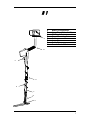
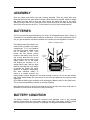
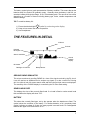
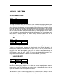
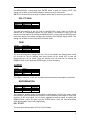
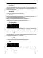
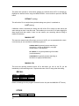
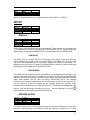
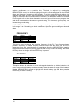
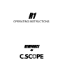
R1
OPERATING INSTRUCTIONS
NEWFORCE
by
R1 - RAPID GET YOU GOING
INSTRUCTIONS
ASSEMBLY
• Assemble stems and adjust for length.
• Use the 25cm (10 inch) search head.
• Twist surplus head lead around stem, allowing enough cable for free
movement of the search head. (Push the cable into the cable slots in the
lower stem to hold it firm).
• Connect search head to detector.
• Insert batteries.
SET-UP
• Rotate the right hand control clockwise to turn the unit on. It also acts as
the volume control. Initially set it to the 3 o’clock position. This switches
the unit on. The display will light up and show an option of “PROGRAM”
mode or “MANUAL” mode.
PROGRAM
MANUAL
•
•
•
Press the ENTER push-button. The display will show 5 possible programs
to choose from, with “COIN INLAND” highlighted.
Press the ENTER push-button to select this program.
The R1 is now ready to use.
SEARCHING
• Keep the search head at a constant height above the ground, i.e. do not
allow the search head to swing higher at the right and left edges of your
swing.
PINPOINTING
• When you hear a tone from the loudspeaker, you have found a target.
• Keep the head close to the ground & move it away from the target.
• Hold the PINPOINT push-button.
• Sweep the head over the target area.
• The sound will be loudest when the head is directly above the target.
CONTROLLING THE DETECTOR
• To adjust the settings on the detector first press the ENTER button to
activate the MENU system. You can still detect normally in this mode.
• Use the MENU/SCROLL control to highlight an option and then press
ENTER to select it.
• To return to the full search screen keep pressing ENTER until it appears.
• For more details on individual menu options read the instruction manual.
IF A PROBLEM IS ENCOUNTERED REFER TO THE FULL INSTRUCTIONS
1
INTRODUCTION
To protect your investment complete both sections of the enclosed guarantee card and
return to C-Scope. This is particularly important in order to obtain the additional parts
guarantee. Please retain the original packing box. In the event that your detector should
ever require to be serviced, this packaging will be most suitable for postal protection.
C-Scope detectors are recognised as the finest detectors available. They are designed with
lasting quality, high technology, and above all, value for money. The only way to realise this
value is to carefully study and understand this instruction manual. You will then be able to
obtain all the advantages designed into your detector. It is also strongly recommended that
you experiment with the detector's operation in air using various test samples, in order to
learn to identify and understand the detector's capabilities and responses. Always remember
that becoming a good metal detectorist is like becoming a good photographer or fisherman,
that is, although it is an advantage to buy the best equipment, having bought it, patience and
hours of practice are needed to become proficient.
If the detector is not working as detailed in this manual then please refer to the
Troubleshooting Page.
FEATURES
•
•
•
•
•
•
•
•
•
•
•
•
•
•
Twin Microprocessor control system
Large Backlit Liquid Crystal Display
CASSY – Computer Aided Search SYstem
RADAR – Real Time Ground Radar Display
High speed target analyser (ID)
Target Pin Point
Audio Discrimination
Program Storage Facility
Full range discrimination
15cm and 25cm diameter lightweight search heads
Continuous Battery Monitor
Recharge Socket
Headphone Socket
Independent volume Control
Switch on the R1 and the opening screen tells you that it is all ready to go, select program
mode and there’s nothing to adjust except the volume. The R1 is optimised and automatic.
There are two powerful computers, each carrying out one million operations every second.
The first carries out all of the signal and target analysis. The second controls the user
interface. This takes the data produced by the first processor and presents it to the user on
the display. The twin processor design enables the R1 to carry on detecting whilst the user
changes settings. This makes it particularly easy to set the correct discrimination levels and
see the effect of different modes. The R1 features a unique Ground Radar display allowing
the user to see the signal being processed by the detector. Any adjustments are made using
the simple to operate MENU driven interface. A single button press gives access to the
MENU. A straightforward rotary control is used to select the item you wish to change, a
press of a button alters the setting – what could be easier?
2
R1
A
A
B
C
D
E
F
G
H
Battery Compartment
Upper Stem & Handle Grips
Din Plug & Socket
Stem Connecting Nut
Cable
Lower Stem
Cable Slots
Search Head & Fastener
B
C
D
E
F
G
H
3
ASSEMBLY
Open the carton and remove the main housing assembly. Twist the plastic stem lock,
located at the end of the upper stem to allow the lower stem to be inserted. Adjust for length
and rotate the lower stem to wrap the cable around the stems and take up any slack.
Allowing enough cable for free movement of the search head, push the cable into the cable
slots in the lower stem to hold it firm. Turn the stem lock to fix it at the desired position.
BATTERIES
The R1 is powered by eight AA batteries or a single 12v rechargeable pack from C-Scope. It
is advisable to use standard alkaline batteries to start with. You can then evaluate the sort of
use you give the detector and decide whether the investment in rechargeables is justified.
Battery Compartment
The batteries should be fitted in the
holder which is located in the battery
compartment. To fit new batteries
first check the power switch on the
unit is switched to OFF. Then
loosen the two captive screws
CHARGER
HEADPHONE
located in the battery cover (do not
SOCKET
SOCKET
fully remove these from the cover)
and remove the cover. Inside is the
battery holder. Lift out the holder
and detach the connector if it is
already fitted. Load it with the eight
batteries ensuring that each battery
BATTERY
is inserted the correct way round,
COMPARTMENT
(direction of batteries alternating).
Roll each individual battery to
ensure it is located correctly and
making proper contact. Replace the connector making sure that it is firm and well seated,
and put the loaded holder into the housing. Fit the cover and tighten the two captive screws
finger tight.
Once fitted the battery type should be set by selecting the Battery option on the Setup menu.
This ensures that the battery condition is correctly displayed
Note: Batteries should not be left in the detector for long periods where they could leak, so
remember to remove them at the end of a day's searching.
BATTERY CONDITION
The battery condition is continuously monitored and displayed. New or fully charged
batteries should cause the entire battery display to be filled. If the battery symbol is empty
then the batteries should be replaced, or recharged if rechargeable batteries are fitted.
4
The battery symbol gives a good representation of battery condition. This means that as the
batteries drain, the symbol will gradually empty. Generally when the battery is half full you
are about halfway through the charge, or life, of that battery pack. The amount of time varies
depending on a number of factors including battery type, make, outside temperature and
detector settings.
TIP! To maximise battery life:
symbol is not showing on the display.
1) Ensure that the backlight
2) Keep volume control set as low as possible.
3) Use Headphones.
THE FEATURES IN DETAIL
ID Block
ID Scale
Rejected
ID Targets
Search Head Size
Ground
RADAR
Display
ID Number
Backlight On Indicator
Battery Monitor
GROUND RADAR SIMULATOR
This unique continuously scrolling RADAR is a view of the signal received by the R1 circuit.
It can be used as an additional tool to analyse any signals. It is also a useful Pin Pointing
aid. It is visible in both full screen search mode and when the first level menus are displayed.
The sensitivity of the RADAR display is controlled by the Pin Point Gain setting.
SEARCH HEAD SIZE
This displays the size of the currently fitted head. If no head is fitted or under certain head
fault conditions the display will show ‘???’.
BATTERY
This shows the currently fitted type, set by the operator when the batteries are fitted. The
symbol shows the condition of the battery. For alkaline batteries a full, completely black
symbol, indicates a voltage of 13volts. An empty symbol is around 8volts. For rechargeable
batteries the upper level is reduced to 10.4V.
5
ID DISPLAY
The ID, (Identifier), numbers in the lower lefthand side correspond to the position of the ID
block on the line at the top of the display. When the R1 has no signal or the signal is too
weak or confusing to identify the display will show ‘??’. The ID line at the top of the screen
will show a block in the relative position when the R1 successfully analyses a signal. The left
hand end of the display is Iron , further right is Silver paper (aluminium foil, new 10p, old 10p
bottle cap and £1.. The solid blocks below the number line indicate ID ranges that will be
rejected by the R1. The Sensitivity of the ID display is controlled by the Motion Gain Setting.
Typical responses to common targets are (your detector may vary slightly):
Object
Ground
Iron
Foil
Ring Pull
Hammered Silver Sixpence
ID No.
0
1,2,3
8
11
10
Object
Old 10p Coin
Bottle Cap
£1 Coin
Cartwheel 1d
New 10p Coin
ID No.
11
13
15
19
9
THE CONTROLS AND WHAT THEY DO
ON/OFF VOLUME
This rotary control is used to turn the unit on and off and adjust the volume level of the
audio.
MENU/SCROLL
This rotary control is used in conjunction with the ENTER button to access the menu system
which is used to control the R1. It has two functions. The first is to highlight the desired
menu option. The second is to adjust the value of a setting up or down.
ENTER
The ENTER push button is used to confirm highlighted menu selections. Once a menu
option has been highlighted then pressing the ENTER button will select that option. If a
value is being set then pushing the ENTER button will store that value. When no menus are
displayed pushing the ENTER key will display the menus.
PIN POINT
Whilst this button is pressed the detector will switch into Pin Point, non-motion, mode. It will
return to normal, motion, mode as soon as the button is released. The ‘RADAR’ display is
reset everytime the Pin Point button is released.
6
MENU SYSTEM
DISCRIMINATION
DISCRIM
SENSITIVITY
AUDIO
PROGRAMS
SET UP
SET
LEARN REJ
LEARN ACC
EDIT
BACK
This range of functions allows you to reject or ignore unwanted signals generated by items
such as pull tabs. It can also act as a Notch Accept or a Notch Reject. There are four
options to set the discrimination level to give maximum flexibility and ease of setting. A black
block under the line of ID numbers indicates that a signal with that number will give no audio
sound, the ID display will still show the signal. NOTE: Ensure that there is no other metal
near the search head when setting the Discrimination by sweeping objects over the head. It
is also advisable to reduce the sensitivity slightly when setting the Discrimination using
Learn Reject or Accept to reduce the chance of any unwanted signals. Once set the
sensitivity may be increased again.
SET
DISCRIM
SENSITIVITY
AUDIO
PROGRAMS
SET UP
SET
LEARN REJ
LEARN ACC
EDIT
BACK
DONE
In this mode the MENU/SCROLL control acts as a conventional Discrimination control.
Turning the control clockwise increases the discrimination level. This is indicated by the
black squares under the I.D. numbers on the display. Iron is to the left (5 and below) and
copper is to the right (15 and above). Sweep a sample of the item you want to ignore over
the search head while adjusting the control until it is rejected. When satisfied press the
ENTER button to store the setting. NOTE: ID 0 cannot be cleared with this control. This is
the ground discrimination block. To alter ID 0 use DISCRIM EDIT, (see below).
LEARN REJECT
DISCRIM
SENSITIVITY
AUDIO
PROGRAMS
SET UP
SET
LEARN REJ
LEARN ACC
EDIT
BACK
DONE
Learn Reject allows you to ‘teach’ the R1 to reject one or more targets that are swept over
the search head. Once Learn Reject is selected the sample or samples are swept several
times over the head. The R1 will then set the disc block at the sample ID point so that any
objects with the same ID as the sample will be rejected.
TIP! This can be used as a Notch Reject facility. First use Discrim Set to accept all signals,
then use Learn Reject to set the specific ID points of objects to be ignored.
7
LEARN ACCEPT
DISCRIM
SENSITIVITY
AUDIO
PROGRAMS
SET UP
SET
LEARN REJ
LEARN ACC
EDIT
BACK
DONE
Learn Accept allows you to ‘teach’ the R1 to accept one or more targets that are swept over
the search head. Once Learn Accept is selected the sample or samples are swept several
times over the head. The R1 will then clear the disc setting at the sample ID point so that
any objects with the same ID as the sample will be accepted. Care should be taken to
ensure that you do not ‘Learn Accept’ ground, ID 0.
TIP! This can be used as a Notch Accept or Token hunting facility. First use Discrim Set to
ignore all signals. Then use Learn Accept to clear the specific ID points of the objects to be
found.
EDIT
DISCRIM
SENSITIVITY
AUDIO
PROGRAMS
SET UP
SET
LEARN REJ
LEARN ACC
EDIT
BACK
DONE
This function enables you to set or reset the Discrimination at any desired point within the
entire range. Once selected a flashing block, (cursor), will appear under the 0 at the left
hand edge of the display. Pressing the ENTER button will toggle the block at the current
cursor position between ACCEPT and REJECT. Rotating the MENU/SCROLL control will
move the cursor. Rotate the control to the desired ID position and press the ENTER key to
either set (REJECT) or clear (ACCEPT) the block. When you have finished rotate the
MENU/SCROLL control clockwise until DONE is highlighted in the lower right hand
corner of the display, then press ENTER.
SENSITIVITY
DISCRIM
SENSITIVITY
AUDIO
PROGRAMS
SET UP
MOTION GAIN
PIN -PT GAIN
TUNE
BACK
These functions set the sensitivity of the R1 to signals.
MOTION GAIN
DISCRIM
SENSITIVITY
AUDIO
PROGRAMS
SET UP
MOTION GAIN
PIN -PT GAIN
TUNE
BACK
This sets the sensitivity of the audio signal and the ID display in normal search or MOTION
mode. The level is set by rotating the MENU/SCROLL control, the current level is indicated
by the bargraph and number on the display. Once the desired level has been set by rotating
8
the MENU/SCROLL control press then ENTER button to store the setting. NOTE: This
setting has no effect on the RADAR display or audio level in Pin Point mode.
TIP! This level should be set as high as possible without the R1 spuriously sounding off.
PIN - PT GAIN
DISCRIM
SENSITIVITY
AUDIO
PROGRAMS
SET UP
MOTION GAIN
PIN -PT GAIN
TUNE
BACK
This sets the sensitivity of the Pin Point, or NON-MOTION, mode. When Pin-Pt Gain is
selected the R1 automatically selects Pin Point mode to aid setting the level. Once the
desired level has been set by rotating the MENU/SCROLL control press then ENTER button
to store the setting. This setting also alters the sensitivity of the RADAR display. NOTE: This
setting has no effect on the normal MOTION search mode.
TUNE
DISCRIM
SENSITIVITY
AUDIO
PROGRAMS
SET UP
MOTION GAIN
PIN -PT GAIN
TUNE
BACK
This sets the threshold or background tone. This is only audible with Silent Search turned
off. As soon as Tune is selected then Silent Search will be turned OFF so that the
background tone will be heard. Once the desired level has been set by rotating the
MENU/SCROLL control press the ENTER button to store the setting.
AUDIO
DISCRIM
SENSITIVITY
AUDIO
PROGRAMS
SET UP
DISCRIM
SIL SEARCH
MODE
BACK
This range of functions control how the audio information about buried targets is presented.
DISCRIMINATION
DISCRIM
SENSITIVITY
AUDIO
PROGRAMS
SET UP
DISCRIM
SIL SEARCH
MODE
PIN -PT OFF
PIN -PT ON
MOTION OFF
MOTION ON
BACK
This enables or disables Audio Discrimination for both Motion and Pin Point modes. Audio
Discrimination gives the operator an indication of the composition of the target by varying the
pitch/tone of the audio signal. For all modes, highlight the desired option by rotating the
MENU/SCROLL control and then press the ENTER button. Note: Pin Point and Motion
Audio Discrimination can be set independently.
PIN - PT OFF
This turns Audio Discrimination OFF for Pin Point Mode.
9
PIN - PT ON
This turns Audio Discrimination ON for Pin Point Mode. This gives a continuous pitch
change across the entire ID range. IE a low tone for iron and a corresponding increase in
pitch for more valuable metals.
MOTION OFF
This turns Audio Discrimination OFF for Motion Mode.
MOTION ON
This turns Audio Discrimination ON for Motion Mode. In this mode bad signals such as Iron
will give a low tone. Good signals will give the normal tone.
NOTE: No tone will be heard if the object has been rejected by the ID.
TIP! Best results will be obtained in this mode if Silent Search is On.
SILENT SEARCH
DISCRIM
SENSITIVITY
AUDIO
PROGRAMS
SET UP
DISCRIM
SIL SEARCH
MODE
OFF
ON
BACK
Silent search will suppress the background tone set by the TUNE setting. In this mode audio
will only be heard if there is buried object. The rest of the time the audio will be silent. Use
the MENU/SCROLL control to highlight the desired option, ON or OFF, and then press the
ENTER button. NOTE: Adjusting the TUNE level will automatically turn Silent Search off.
OFF
Turns Silent Search OFF. In this mode, a constant background tone will be heard. The level
of this tone is set by the SENSITIVITY - TUNE option.
ON
Turns Silent Search ON. In this mode, no background tone is heard.
MODE
DISCRIM
SENSITIVITY
AUDIO
PROGRAMS
SET UP
DISCRIM
SIL SEARCH
MODE
ANALOG
DIGITAL
BACK
This function alters the way in which the audio tone is generated. It only affects normal
Motion search mode. Use the MENU/SCROLL control to highlight the desired option, then
press the ENTER button.
ANALOG
10
The audio signal comes straight from the R1 receiver circuit. It allows the operator to listen
to the true signal level and can allow the experienced user to ‘understand’ signals better. It
does have the disadvantage that smaller, deeper objects give fainter signals.
DIGITAL
The audio signal is directly controlled by the R1 computer. In this mode the audio signal is
either on or off. This means that a deep object will give the same audio volume as a shallow
object. This can make the initial location of an object easier and more positive but does not
convey any other information.
PROGRAMS
DISCRIM
SENSITIVITY
AUDIO
PROGRAMS
SET UP
GR’ND TYPE
OPTIONS
RECALL
STORE
BACK
These functions allow the operator to store and recall the set up of the R1. Up to two
programs can be stored. A program will store all of the current settings including
Discrimination, Sensitivity, Frequencies etc. It will not store the Display Contrast and
Brightness settings. These are stored separately and retrieved automatically at turn on.
Once Store or Recall is selected rotate the MENU/SCROLL control to highlight the Program
to be stored or recalled and then press the ENTER button. The R1 comes with the first three
programs preset to commonly used settings. The COIN INLAND Program is set for high
sensitivity to precious metals, the ALL METAL Program for deep seeking of all metals and
COIN BEACH Program for Beach use.
GROUND TYPE
DISCRIM
SENSITIVITY
AUDIO
PROGRAMS
SET UP
GR’ND TYPE
OPTIONS
RECALL
STORE
BACK
INLAND
BEACH
This allows the operator to select between use on normal inland sites or wet sand sites such
as the beach. Use the MENU/SCROLL control to highlight the desired option and then press
the ENTER button.
INLAND
This will set the R1 ground reject circuit to normal ground conditions.
BEACH
This will set the R1 ground reject circuit to cope with the extreme conditions found on wet
sand. NOTE: As beach conditions are so variable some adjustment of the GROUND ADJ
setting may be required.
OPTIONS
DISCRIM
SENSITIVITY
AUDIO
PROGRAMS
SET UP
GR’ND TYPE
OPTIONS
RECALL
STORE
BACK
DEFAULT
LAST
MANUAL OFF
MANUAL ON
11
This allows the operator to select which settings are restored when the R1 is switched on.
Highlight the desired choice using the MENU/SCROLL control and then press the ENTER
button.
DEFAULT (setting)
This will tell the R1 to load the factory default settings every time it is switched on.
LAST (setting)
If MANUAL mode is selected (see below) this will tell the R1 to switch on with exactly the
same settings as when it was last used. This enables you to turn the R1 off when digging for
deep targets and then switch it back on and resume your searching without having to
readjust the detector.
MANUAL OFF
This turns the manual mode off so when you turn on the R1 you are presented with a short cut to the easy to use manufacturer defined programs of:
COIN INLAND for general purpose searching on
most sites i.e. those not affected by very high
mineralisation or salt deposits.
ALL METAL for very deep searching of all metals
(no discrimination).
COIN BEACH for general purpose searching on
the beach or highly mineralised sites.
MANUAL ON
This turns the opening selection screen off so that when you turn on the R1 you are
immediately in the searching mode. Experienced users of the R1 may prefer this setting.
RECALL
DISCRIM
SENSITIVITY
AUDIO
PROGRAMS
SET UP
GR’ND TYPE
OPTIONS
RECALL
STORE
BACK
COIN INLAND
ALL METAL
COIN BEACH
USER 1
USER 2
Recalls all settings from the program selected from the list (see also MANUAL OFF above).
STORE
DISCRIM
12
GR’ND TYPE
USER 1
SENSITIVITY
AUDIO
PROGRAMS
SET UP
OPTIONS
RECALL
STORE
BACK
USER 2
Stores all current settings into the program selected, either USER 1 or USER 2.
SETUP
DISCRIM
SENSITIVITY
AUDIO
PROGRAMS
SET UP
DISPLAY
GROUND ADJ
FREQUENCY
BATTERY
BACK
DISPLAY
DISCRIM
SENSITIVITY
AUDIO
PROGRAMS
SET UP
DISPLAY
GROUND ADJ
FREQUENCY
BATTERY
BACK
CONTRAST
BRIGHTNESS
These options allow the display settings to be adjusted. These settings are stored when the
R1 is switched off and will be restored when it is turned back on. To select, highlight the
desired option by rotating the MENU/SCROLL control and the press the ENTER button.
CONTRAST
This option sets the contrast level or viewing angle of the display. Once set it shouldn’t
require adjustment. However, if the R1 is used at dawn or dusk when the sun is low in the
sky then some adjustment may be required to improve the visibility of the display. The
desired level should be set by rotating the MENU/SCROLL control and then pressing the
ENTER button when satisfied, this will store the setting.
BRIGHTNESS
This option sets the brightness level of the backlight. In normal daylight the backlight is not
required and it should be set to 0. At night or in conditions of poor light the backlight level
should be adjusted by rotating the MENU/SCROLL control and then pressing the ENTER
button when satisfied, this will store the setting. IMPORTANT NOTE: The backlight
consumes a lot of power compared with the low consumption circuitry of the rest of the R1.
For this reason to ensure long battery life the backlight should only be used where
necessary and the brightness level kept to a minimum. The brighter the backlight the more
power it uses and the shorter the battery life will be. When the backlight is on the
symbol appears on the display to prevent inadvertent use.
GROUND ADJUST
DISCRIM
SENSITIVITY
AUDIO
PROGRAMS
SET UP
DISPLAY
GROUND ADJ
FREQUENCY
BATTERY
BACK
The default setting of 50 is a good general setting and should be adequate for most sites.
However, a fine adjustment is provided to allow the operator to adjust the R1 to give
13
optimum performance on a particular site. The level is adjusted by rotating the
MENU/SCROLL control. An incorrect setting will result in a fluctuating signal on the RADAR
display and frequent ‘0’ targets on the ID display. To find the optimum ground setting, raise
and lower the head above an area of ground free from any targets then adjust the ground
setting for minimum audio fluctuation and ID indications. An alternative method is to set the
Pin Point gain to 8 and then lower the head to an area of ground free from any targets. If the
audio level increases then decrease the ground setting, if it decreases, (goes quiet), then
increase the ground setting.
NOTE: If BEACH is selected then an incorrect ground setting will result in frequent ID targets
in the range 3 to 6 depending on beach conditions. Adjust the ground setting as described
above.
FREQUENCY
DISCRIM
SENSITIVITY
AUDIO
PROGRAMS
SET UP
DISPLAY
GROUND ADJ
FREQUENCY
BATTERY
BACK
LOW
MIDDLE
HIGH
This can be used to change the operating frequency of the R1. Three frequencies are
provided. Generally the middle frequency should be used but the others can be used if
interference from other metal detectors is experienced. Use the MENU/SCROLL control to
highlight the desired frequency and the press the ENTER key to store the setting. NOTE: the
frequency does not change until the ENTER key is pressed.
BATTERY
DISCRIM
SENSITIVITY
AUDIO
PROGRAMS
SET UP
DISPLAY
GROUND ADJ
FREQUENCY
BATTERY
BACK
RECHARGE
ALKALINE
This option allows the selection of either rechargeable batteries or alkaline batteries. It is
used to ensure that the battery monitor accurately shows the state of charge of the batteries.
Use the MENU/SCROLL control to highlight the desired battery type and then press the
ENTER key to store the setting.
14
GENERAL HINTS
Pin Pointing
Move the search head to one side of the target. Press and hold the Pin Point button.
Sweep the search head over the target slowly whilst monitoring the RADAR display.
The target is directly below the centre of the search head when the signal is largest. If
the RADAR signal is too broad then either move the head closer to the target and
release and press the Pin Point button, or simply raise the search head slightly off of
the ground whilst sweeping the head over the target. Make a mental note of the
position of the maximum signal then turn through 90 degrees and repeat the above
procedure. Again make a mental note of the position of maximum signal. The point at
which both signals are maximum is the position of the target. Dig carefully to avoid
damaging your find.
Target position
Second Sweep
X
First Sweep
Detection Range
Your R1 is a top performance detector but adverse soil conditions can significantly reduce
the depth of detection.
Detection ranges will vary depending on the size of the object, the length of time an object
has been buried, and the type of ground the object is buried in.
The best ground conditions are well compacted soils and coins can be found at the greatest
depth if the object has been buried for some time and the coin has interacted with the salts
in the ground, thereby appearing larger to the detector. The worst conditions for detecting
are on loosely compacted or freshly dug ground or when the object has only recently been
buried. In these conditions detection range will be reduced. 90% of all artefacts are found
within 15cm of the surface.
15
Determining the Target Size
An operator who is familiar with their instrument will be able to do an excellent job of
determining object size, shape and depth before he digs. This technique is learned from
careful analysis of the RADAR and audio signal coming from the detector. Each time a
signal is heard, listen for any peculiar characteristics it may have, determine over how large
an area you get a detector signal, and try to 'outline' the object before you dig.
After digging up the object, compare the object size, shape, depth and position in the ground
with signal information you received before digging. After careful analysis of many signals
you will learn to 'read' the hidden target before digging.
16
Specification
Battery Type:
Supply Voltage:
Supply Current:
8 x AA, MN1500 or equivalent, Alkaline cells recommended.
12v DC (nominal), 13.8v DC (max)
55mA (no backlight)
100mA (backlight full on)
Battery Life:
40 Hours normal detecting using Alkaline batteries and no backlight
Battery Indicator:
Alkaline:
Rechargeable:
Audio Frequency:
Full 13.2V
Full 10.8V
Empty 8.5V
Empty 8.5V
100Hz to 5.5kHz, 714Hz (nominal)
Transmit frequency: 6.097kHz, 6.250kHz, 6.410kHz
Search Coils:
25cm concentric
15cm ‘2D’
Detection Ranges:
(Typical in air performance, Motion mode)
Hammered 6d
£1 coin
‘old’ 10p
Cartwheel 1d
20cm
30cm
32cm
33cm
Factory Program Settings.
Setting
DISCRIM (reject)
MOTION GAIN
PIN POINT GAIN
AUDIO DISC
SILENT SEARCH
AUDIO MODE
FREQUENCY
GROUND TYPE
Coin Inland
Program
0-3
14
14
PIN POINT OFF
MOTION OFF
OFF
ANALOG
LOW
INLAND
All Metal
Program
0
14
14
PIN POINT ON
MOTION ON
ON
DIGITAL
LOW
INLAND
Coin Beach
Program
0-5,10
12
12
PIN POINT OFF
MOTION OFF
ON
DIGITAL
LOW
BEACH
17
MENU STRUCTURE
DISCRIMination
SET
LEARN REJect
LEARN ACCept
EDIT
SENSITIVITY
MOTION GAIN
PIN PoinT GAIN
TUNE
AUDIO
DISCRIMination
PIN PoinT OFF
PIN PoinT ON
MOTION OFF
MOTION ON
SILent SEARCH
OFF
ON
MODE
ANALOG
DIGITAL
PROGRAMS
GRouND TYPE
INLAND
BEACH
OPTIONS
DEFAULT
LAST
RECALL
COIN INLAND PROGRAM
ALL METAL PROGRAM
COIN BEACH PROGRAM
USER PROGRAM 1
USER PROGRAM 2
STORE
USER PROGRAM 1
USER PROGRAM 2
SETUP
DISPLAY
CONTRAST
BRIGHTNESS
GROUND ADJust
FREQUENCY
LOW
MIDDLE
HIGH
BATTERY
RECHARGEABLE
ALKALINE
18
OPTIONAL ACCESSORIES from C-Scope
Headphones:
Headphones not only extend battery life but also improve sensitivity by reducing external
noises. The headphones should be fitted with a standard stereo 6.35mm, (1/4 inch), jack
plug. The headphone socket is located under the protective cap in the battery housing.
(NOTE: Stereo mode must be selected on headphones fitted with a stereo/mono switch).
Rechargeable battery pack:
A shrink wrapped pack of 8 rechargeable Nickel Cadmium batteries to replace the standard
batteries and holder.
Battery charger:
The C-Scope battery charger is designed to charge the rechargeable pack safely and
efficiently.
CHARGING BATTERIES
A battery charge socket is provided for use with the C-Scope battery charger (see
Accessories) and is located under the protective cap in the battery housing. (The smaller of
the two sockets.) Inserting the charger will automatically remove the power from the detector
so the charger must be removed to do a battery check. Do not attempt to recharge standard
batteries. It will take approximately fourteen hours to fully recharge flat batteries with the CScope charging unit.
For further information, and a price list, for all C-Scope accessories please telephone
(01233) 629181, e-mail: [email protected] or contact your local dealer.
19
THE IMPORTANCE OF THE RIGHT
APPROACH
Treasure hunting can be a profitable and rewarding hobby, if approached in a patient and
diligent manner. Time spent researching to locate a worthwhile site for a search can be time
wasted if your search is hasty and erratic. To achieve maximum results it is important then,
to decide on your approach to any particular site in advance of the actual search.
Tactics will be decided by the type of site - it is more profitable to scan a small area
thoroughly than to conduct a haphazard search of the total site. However, when the site is
too far away for you to make several return visits, a plan should be adopted which gives
maximum coverage, at the same time as indicating the most likely area for detailed search.
Your detector alone is not a guarantee of successful treasure hunting. Any detector needs
an operator and for the best results the operator needs the right approach, attitude and
technique. Too many beginners neglect the importance of pre-planning and research before
using their detector in the field, and patience and technique during the actual search.
Your detecting should begin with some background work before the day of the actual
search. The extent and thoroughness of your research will be one of the major factors in the
success of your detecting. You should aim to get as complete an understanding as possible
of the local history and geography.
The key to the choice of site is to think of people, where they congregated over the past few
hundred years. What were their customs and pursuits? Where did they spend money?
Where did they carry money? The answers are not Roman sites, nor are they associated
with mystic treasure stories of crocks of gold. Rather, they are unassuming, undramatic
places, like public footpaths and ancient rights of way, old houses and so on.
When you have chosen your site, allocate a whole day from early morning to early evening
for the search. Make sure you have all the equipment you are likely to need. Your detector
should be checked before starting out, and you should always carry a spare set of batteries.
You will also need a strong, sharp trowel. It is also a good idea to have a set of lines and
pins so that you can lay out your search area scientifically.
Most beginners make the mistake of rushing about hoping to chance upon a rare find. If for
example there happened to be a valuable ring that was buried 15cm deep on the site you
were searching, if you rushed about haphazardly and quickly on the site, the odds would be
very much against you finding it. On the other hand, if you pegged out the area scientifically
and searched slowly and thoroughly, the odds of finding the ring would be very much more
in your favour.
Remember, BE PATIENT and WORK SLOWLY. Do not try to cover too large an area,
restrict yourself to a small area and work through it thoroughly. Make a note of the position
and the extent of the area, and then when you return you can start again further on without
missing any ground or covering the same area twice.
It is also important to keep the detector head as close to the ground as possible. Ideally, you
should 'iron' the ground with the search head of the detector, so that you do not lose any
detection range. Similarly, if you work slowly and carefully you should be able to distinguish
the faint signals as well as the clear-cut signals and further increase your finds.
20
The technique of getting the best out of your detector is not learnt overnight. You need to get
as much experience as possible so that you can recognise every kind of signal. Indeed, a
good detector operator can often tell you what is being detected before it is unearthed.
Search Head Position
It is essential that the search head is kept close and parallel to the ground as in B. Do not
hold the search head too high above the ground, or at an odd angle as in A, C, D as you will
be apt to miss finds.
SWEEPING TECHNIQUE
For extremely small object searching, such as coins, rings, nuggets, etc. lower the search
head to within 1 inch of the ground. Sweeping the coil from side to side in a straight line in
front of you. Keep the coil at a constant height as you sweep from side to side. Move the
head at a rate of 0.5 metre per second.
The optimum sweep rate must be determined by each operator. The detector should be held
comfortably in the hand, with the head held as close to the ground as possible. As the
detector is scanned from side to side in front of the operator, the search head should be
advanced approximately two-thirds the diameter of the coil. This keeps the operator moving
ahead, and it allows some overlapping of each sweep. This overlapping ensures that nothing
will be missed. It is well to note here that the operator should not rush. This is one of the
most common mistakes made by detector users. If you rush, you will not adequately cover
the ground.
21
CODE OF CONDUCT
1. Do not trespass. Obtain permission before venturing on to any private land.
2. Respect the Country Code. Do not leave gates open when crossing fields, and do not
damage crops or frighten animals.
3. Do not leave a mess. It is simple to extract a coin or other small objects buried a few
inches under the ground without digging a great hole. Use a sharpened trowel or knife to
cut a neat circle or triangle (do not remove the plug of earth entirely from the ground);
extract the object; replace the soil and grass carefully and even you will have difficulty in
finding the spot again.
4. Help to keep countryside tidy - and help yourself. Bottle tops, silver paper and tin cans
are the last thing you should throw away. You could well be digging them up again next
year. Do yourself and the community a favour by taking the rusty iron and junk you find
to the nearest litter bin.
5. If you discover any live ammunition or any lethal objects such as an unexploded bomb or
mine, do not touch it. Mark the site carefully and report the find to the local police.
6. Report all unusual historical finds to the landowner.
7. Familiarise yourself with the law relating to archaeological sites. Remember it is illegal
for anyone to use a metal detector on a scheduled ancient monument unless permission
has been obtained from the Historic Buildings and Ancient Monument Commission for
England or the Secretary of State for the Environment in Scotland and Wales.
8. Remember that when you are out with your metal detector, you are an ambassador for
our hobby. Do nothing that may give it a bad name.
9. The law relating to treasure finds must be followed. In the U.K. Details of the law can be
obtained from the Department of Culture, Media & Sport (Tel: 0207 211 6200) who
produce excellent literature to help you to understand how the law affects you and your
hobby.
CARE OF YOUR DETECTOR
Storage
When not in use your detector should be stored in a dry warm environment. If it is not to be
used for any length of time it is advisable to remove the batteries to avoid leakage which
could cause serious damage. The working life of your detector will be shortened by careless
use or neglect of the unit. Think of your detector as a scientific instrument. Your detector is
designed to withstand rugged handling on any terrain, but misuse or lack of due attention will
tell in the end. After using your detector in a hostile environment (salt water, sand, etc.) The
exterior parts should be wiped clean with a damp cloth, paying particular attention to the
head and stems, then carefully wipe dry. The search head securing bolt should be
periodically removed and lubricated to prevent seizing.
.DO NOT use solvents or detergents on any part of the detector.
22
TROUBLESHOOTING
(a)
(b)
(c)
Check the condition of batteries under load using the battery monitor symbol. (See
Battery Check Procedure).
Check that the search head is properly attached to the control box via the search head
cable connector.
Interchange batteries and ensure batteries are correctly seated in the holder and that
the battery connector is securely attached to the battery holder.
Oscillating Signal
(a)
(b)
(c)
This could be due to poor battery connections. Ensure that they are tight and the
batteries are securely clipped into place.
Loose search head cable connection - tighten.
Interference from a vehicle using a radio transmitter, or possibly a stationary source of
electromagnetic radiation such as an electric fence or radio transmitter. If this occurs
then reduce the sensitivity. If the problem persists then the best remedy is to wait until
the transmission stops.
Intermittent Sound from Speaker
(a)
(b)
(c)
(c)
This could be due to poor battery connections. Ensure that they are tight and the
batteries are securely clipped into place.
Loose search head cable connection - tighten.
Ensure search head cable is pushed into the cable slots in the lower stem.
Radio interference (see above).
Poor or No Contrast on Display
(a)
(b)
This could be due to poor battery condition. Ensure that batteries are in good
condition.
The R1 internal storage could be corrupted. To reset the detector ensure the R1 is
turned OFF, press and hold the ENTER button, turn the R1 ON wait 5 seconds. You
will be asked if you wish to reset the detector. Use the MENU/SCROLL control to
highlight YES then press the ENTER button. The R1 will then be reset to factory
settings.
No Sound or Partial Sound from Headphones
(a)
(b)
(c)
On headphones fitted with stereo/mono switch, ensure stereo is selected.
Ensure headphone connector is fully inserted into socket.
Try another set headphones or try headphones on another piece of equipment.
23
Further Information
If you experience any difficulty in operating your R1 or have any questions on the information
in your R1 Operating Instructions Manual, please do not hesitate to phone our Customer
Service Department on +44 (0)1233 629181 or e-mail: [email protected]
Before returning a detector for repair to C-Scope ensure you have done the
following:(a)
(b)
(c)
24
Read the instructions thoroughly.
Tried new batteries and checked procedure outlined above.
Return your detector with a letter giving full details of fault.
This equipment conforms to the EMC Directive 89/336/EEC.
System performance may be impaired by unusually strong electromagnetic fields.
Kingsnorth Technology Park, Wotton Road,
Ashford, Kent TN23 6LN
United Kingdom
Telephone: +44 (0) 1233 629181 Fax: +44 (0) 1233 645897
email: [email protected], web: www.cscope.co.uk
Pt No. B1058 Issue 4 (07/06)