1
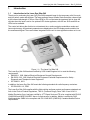
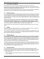
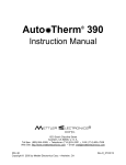
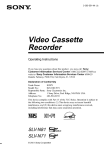
Instruction Manual ® 1333 South Claudina Street Anaheim, CA 92805, U. S. A. Toll free: (800) 854–9305 • Telephone: (714) 533–2221 • FAX: (714) 635–7539 Web Site: http://www.mettlerelectronics.com • Email: [email protected] IR9–39 Copyright © 2005, 2010 by Mettler Electronics Corp.—Anaheim, CA Rev.F_07/03/12 Mettler Electronics Corp.— Rev.F_07/03/12 2 Laser Sys*Stim 540, Therapeutic Laser— Rev.F_07/03/12 TABLE OF CONTENTS 1 1.1 1.2 1.3 1.4 1.5 1.6 1.7 2 2.1 2.2 2.3 2.4 3 3.1 4 4.1 4.2 4.3 5 5.1 5.2 5.3 5.4 5.5 5.6 5.7 5.8 5.9 6 6.1 6.2 6.3 Introduction 5 Introduction to the Laser Sys*Stim 540 Introduction to this manual Safety precautions Caution Shipping damage Package contents Limited Warranty 5 6 6 6 6 6 7 Symbol Glossary and List of Abbreviations 9 Operational controls, displays, receptacles and symbols Abbreviations Top panel—Controls and Indicators Laser and Cluster Applicators – Controls, Output Aperture and Indicators 9 9 10 12 Installation 15 Installation Instructions 15 Operating Instructions 17 General instructions Instructions for operation User program memory 17 18 20 Laser Therapy 21 Introduction What is a Laser? Laser interaction with the Human Tissue Wavelengths Pulsed Modes Method of Laser Therapy Laser Dosage SLD/LED Cluster vs. Laser Application References 21 21 21 21 21 22 22 22 21 Indications, Contraindications and Precautions for Low Level Infrared Laser Therapy 25 Indications Contraindications Precautions 25 25 25 3 Mettler Electronics Corp.— Rev.F_07/03/12 7 7.1 7.2 7.3 7.4 7.5 8 8.1 8.2 8.3 8.4 9 9.1 9.2 Maintenance and Troubleshooting 27 Cleaning and disinfecting Routine Maintenance Changing fuses Laser Output Sensor Troubleshooting the Laser Sys*Stim 540 27 27 27 28 28 Specifications 29 General Information Laser Performance Laser Applicator Specifications: Optional Cluster Applicator Specifications: 29 29 30 30 Accessories 31 Ordering Information Laser Sys*Stim 540 Accessories 31 31 LIST OF FIGURES 1.1 2.1 2.2 2.3 3.1 3.2 4.1 4 The Laser Sys*Stim 540 Controls and Indicators on the Top Panel Laser Applicator Description Laser Applicator Label Descriptions Laser Sys*Stim 540, Controls and Receptacles Located on the Front of the Unit Laser Sys*Stim 540, Power Cord Connection Laser Sys*Stim 540 Membrane Control Panel and LED Indicators 5 11 12 13 13 14 15 Laser Sys*Stim 540, Therapeutic Laser— Rev.F_07/03/12 1 Introduction 1.1 Introduction to the Laser Sys*Stim 540 Thank you for purchasing the Laser Sys*Stim 540 therapeutic laser for the temporary relief of muscle and joint aches, pains and stiffness. The laser applicator has a AlGaAs Diode that emits coherent light at the infrared wavelength of 785 nm. Blue LEDs at 470 nm illuminate the treatment field to show the clinician when the laser is active. An optional LED cluster applicator, with 950 nm SLDs and 660 nm LEDs is also available. The control unit allows the clinician to set treatment time, continuous/pulse modulation modes and laser output energy. All treatment parameters are displayed on the LED displays and controlled via the membrane keypad. There are holders integrated into the unit to store applicators when not in use. Figure 1.1— The Laser Sys*Stim 540 The Laser Sys*Stim 540 has been certified by SGS United Kingdom Ltd. to meet the following requirements: EN60601-1 1990, Medical Electrical Equipment General Requirements EN 60601-2-22, 1996, Medical Electrical Equipment Particular Requirements for Safety Diagnostic and Therapeutic Laser Equipment IEC 60825-1, 2001 In addition, the Laser Sys*Stim 540 meets the following standards for radio frequency emissions: IEC/EN 60601-1-2, 2002 The Laser Sys*Stim 540 complies with the light-emitting and laser product performance standards set forth in the Code of Federal Regulations, Title 21 (Food and Drugs), Parts 1040.10 and 1040.11. Mettler Electronics Corp. has been certified by VTT Expert Services LTD to be compliant with EN ISO 13485:2003 and MDD 93/42/EEC Annex II requirements. In addition, Mettler is certified by DQS Medizinprodukte GMBH to be compliant with ISO 13485:2003 (CMDCAS) Canadian Medical Device requirements. 5 Mettler Electronics Corp.— Rev.F_07/03/12 1.2 Introduction to This Manual Read the contents of this manual before treating patients with the Laser Sys*Stim 540. This manual has been written to assist you with the safe operation of the Laser Sys*Stim 540. It is intended for use by the owners and operators of the Laser Sys*Stim 540. The goal of this manual is to direct the correct operation and maintenance of this unit. The specifications and instructions presented in this manual are in effect at the time of its publication. These instructions may be updated at any time at the discretion of the manufacturer. 1.3 Safety Precautions The Laser Sys*Stim 540 operates with high voltages. Qualified biomedical technicians with training in service of therapeutic laser systems should perform servicing of the Laser Sys*Stim 540 or it should be returned directly to the factory. To maximize safety during use, the unit should be plugged into a grounded wall outlet or run off the battery. General safety guidelines for medical electronic equipment should be followed. Service may be obtained from the manufacturer by sending the Laser Sys*Stim 540 in its original shipping container to Mettler Electronics Corp., 1333 South Claudina Street, Anaheim, CA 92805, ATTN: Service Department. (Telephone toll free: (800) 854–9305, Alternate telephone number: 1 (714) 533–2221) NOTE: All warranty repairs must be performed by Mettler Electronics Corp. or by a service facility authorized by Mettler Electronics to perform warranty repair work. A service manual for the Laser Sys*Stim 540 is available from Mettler Electronics Corp. for a nominal charge. 1.4 Caution Federal law restricts the sale of this device to, or on the order of a physician, dentist, veterinarian or any other practitioner licensed by law of the state in which he practices. Use of controls or adjustments or performance of procedures other than those specified herein may result in hazardous exposure to laser light energy. Treatment should be administered only under the direct supervision of a health care professional. 1.5 Shipping Damage Your new Laser Sys*Stim 540 is shipped complete in one carton. Upon receipt, please inspect the cartons and the unit and its accessories for visible and hidden damage. If you discover any damage, hold all shipping materials, including the carton, and call the shipping agent who delivered the unit. They are responsible for all damage in transit; therefore, all claims should be filed directly with them. The factory will not be responsible for any damage in shipment, nor allow any adjustments unless proper formal claim has been filed by the receiver against the carrier. The carton in which your new Laser Sys*Stim 540 was received is specially designed to protect the unit during shipping. Please retain all shipping materials in the event that you will need to return your unit for servicing. NOTE: All warranty repairs are to be performed by Mettler Electronics Corp. or an authorized Mettler Electronics warranty repair center. 1.6 Package Contents Your new Laser Sys*Stim 540 comes complete with all the necessary components to perform therapeutic laser treatements. Below is a list of items that are included in the shipping carton. There are also other optional accessories available for this unit. They are listed at the back of this book. 1. Laser Sys*Stim 540 2. One laser applicator with a AlGaAs Diode that emits coherent light at the infrared wavelength of 785 nm, (ME5401) 6 Laser Sys*Stim 540, Therapeutic Laser— Rev.F_07/03/12 3. Two pair of protective Uvex glasses (5403) 4. One detachable hospital grade line cord (7293) 5. Instruction manual and warranty card 1.7 Limited Warranty The Laser Sys*Stim 540 therapeutic laser unit is warranted against defects in materials and workmanship for a period of two years from date of purchase, (one year on applicators). During the applicable warranty period Mettler Electronics Corp. will, at its discretion, either repair or replace the Product without charge for these types of defects. Batteries are excluded from this warranty except where it can be demonstrated that any battery failure was caused by a malfunction in the Laser Sys*Stim 540. This warranty excludes glass or ceramic parts. For service under this warranty, the Product must be returned by the buyer within the applicable warranty period to Mettler Electronics Corp. Shipping charges to Mettler Electronics Corp. under this warranty must be paid by the buyer. The buyer must also include a copy of the sales receipt or other proof of the date of purchase. If the Product is returned without proof of the date of purchase, it will be serviced as an out–of–warranty product at Mettler Electronics Corp.'s prevailing service rates. Alteration, misuse, or neglect of the Product voids this warranty. Except as specifically set forth above, Mettler Electronics Corp. makes no warranties, express or implied, including without limitation any implied warranty of merchantability or fitness for a particular purpose, with respect to the Product. If any implied warranties apply as a matter of law, they are limited in duration to one year. Mettler Electronics Corp. shall not be liable for any indirect, special, consequential or incidental damages resulting from any defect in or use of the Product. Any legal action brought by the buyer relating to this warranty must be commenced within one year from the date any claim arises and must be brought only in the state or federal courts located in Orange County, California. Some states do not allow limitations on how long an implied warranty lasts, or the exclusion or limitation of incidental or consequential damages, so the above limitations or exclusions may not apply to the buyer. This warranty gives the buyer specific legal rights, and the buyer may also have other rights which vary from state to state. 7 Mettler Electronics Corp.— Rev.F_07/03/12 8 Laser Sys*Stim 540, Therapeutic Laser— Rev.F_07/03/12 2 Symbol Glossary and List of Abbreviations 2.1 Symbol Glossary Time display symbol Output display symbol Battery symbol Down arrow for time and intensity Up arrow for time and intensity Program and Pulse selector buttons Attention, consult instruction manual. Type BF Equipment—Class I The applied parts (treatment applicators) of this equipment are rated as Type “BF” which means that the applied parts are suitable for placement on the external surface of the body. Warning symbol indicates that the device emits laser energy and that proper precautions listed in this manual need to be taken. Fuse rating symbol 2.2 Abbreviations CW AlGaAs Hz LED μs min mW mm nm s Ser. No. SLD SN W V A — — — — — — — — — — — — — — — — Continuous wave (100 % duty cycle) Aluminum Gallium Arsenide Hertz (pulses per second) Light Emitting Diode Microsecond (1 x 10⁻⁶ seconds) Minutes milliwatt (1 x 10⁻³ watts) millimeter (1 x 10⁻³ meters) nanometer (1 x 10⁻⁹ meters) Seconds Serial Number Super Luminescent Diode Serial Number Watts Volts Amperes 9 Mettler Electronics Corp.— Rev.F_07/03/12 2.3 Top panel—Controls and Indicators 1 6 2 7 8 3 9 4 10 5 11 Figure 2.1—Controls and Indicators on the Top Panel 1. Timer Display 6. Energy Display 2. Timer “Up” and “Down 7. Output “Up” and “Down 3. Mode Display 8. Program Select 4. Battery Level Bargraph 9. Pulse Mode Select 5. Charging Indicator 10. Laser Output Bargraph 11. Laser Output Sensor LED Displays The LED displays show all the operating parameters of the Laser Sys*Stim 540. These are: Treatment time: this 4 digit display is used to set the treatment time, and during treatment the display counts down to show the time remaining, see figure 2.1(1). Treatment energy: this 3 digit numeric display is used to set the energy dosage for the treatment, see figure 2.1(6). 10 Laser Sys*Stim 540, Therapeutic Laser— Rev.F_07/03/12 Pulse mode: this 11 position display shows the selected pulse mode frequency. If SWEEP is selected, during the treatment the display will show the current pulse mode, see figure 2.1(3). Laser output: this bargraph display shows the amount of incident laser energy measured by the LASER OUTPUT SENSOR, the 100% level indicates the laser is at 100% i.e. 80mW. See figure 2.1(10). If the bargraph has several bars illuminated beyond the '%' mark (ie total of 15 segments illuminated) is possible the laser is emitting at a higher level, it is recommended the unit be checked for calibration as soon as possible by a service facility specializing in medical lasers. Battery level: this bargraph display shows the battery level range 0 to 100%, see figure 2.1(4). Laser Output Sensor This sensor is used to display and verify the output from the laser applicator when laser energy is being emitted. Note: Ensure measurement is performed using Continuous Pulse Mode, figure 2.1(11). Please note: This sensor does not work with the cluster applicator. Membrane Keypad These six keys enable the operator to input and manipulate the user selectable parameters of the Laser Sys*Stim 540 to obtain the desired treatment. Timer “Up” and “Down”: these two arrow keys are used to set the treatment time, which is displayed on the display above the keys, see figure 2.1(2). Output “Up” and “Down”: these two arrow keys are used to set the treatment dosage energy, which is displayed on the display above the keys, see figure 2.1(7). Pulse Mode: this key selects the Pulse mode which is displayed on the display above the key, pressing the key indexes the Pulse mode selection to the right, see figure 2.1(9). Program: this key selects the 0 to 9 available user programmable memories, allowing the practitioner to store and recall configurations. Pressing the key indexes through the memories, figure 2.1(8). Mains/Charging Indicator This indicator is illuminated when the mains supply is applied to the unit. This will enable the battery to be charged during use, figure 2.1(5). 11 Mettler Electronics Corp.— Rev.F_07/03/12 2.4 Laser and Cluster Applicators – Controls, Output aperture and Indicators 1 2 3 4 5 6 Figure 2.2—Laser Applicator Description 1. Laser Output Aperture 2. Aperture Warning Label 3. Laser On Indicator 4. “Laser Activate” Capacitance Switch 5. Increase Output Energy (repeat dosage) 6. Decrease Output Energy Laser Warning Labels The laser applicator has four warning labels, two of these labels are visible on figure 2.2. These two labels are the international Laser Hazard symbol which is located on the “Laser Activate” capacitance switch pad, and the other is the yellow Laser Aperture label which has an arrow pointing to the laser aperture at the front of the laser applicator. The two other labels are shown in figure 2.3 below. 1 2 Figure 2.3—Laser Applicator Label Descriptions 1. Laser Aperture Label 12 2. Explanatory Label Laser Sys*Stim 540, Therapeutic Laser— Rev.F_07/03/12 Laser On Indicator The green Laser On indicator illuminates when the laser is lasing. When the laser beam is extinguished after the treatment time has elapsed the Laser On indicator will turn off. Note: When the Laser Sys*Stim 540 power is switched on by turning the keyswitch, the Green Indicator will flash momentarily, this is normal and is provided as a start-up lamp test. Please Note: When there is a problem with the laser applicator, the Laser On indicator will glow an amber color. The blue LEDs will not be illuminated, but it is possible that the laser diode will be active and therefore eye protection is still warranted. If the amber indicator light comes on and stays on when the capacitive switch is activated, return the laser applicator for service. Laser Activate Capacitance Switch The “Laser Activate” capacitance switch is located on the handle section of the laser applicator membrane. The capacitance switch works by measuring the practitioners body capacitance across a sensing ‘Pad’. The ‘Pad’ is a rectangular shaped area and has the words “Laser Activate” on it. By placing a finger or thumb over the ‘Pad’, the capacitance is increased and the switch is activated. The advantage is that it requires no force to actuate, and therefore reduces the strain a practitioner may experience holding down a mechanical switch for possibly long periods of time. Increase/Decrease Output Energy Keys The two membrane keys on the handle section of the applicator are used to increase or decrease the dosage energy. During the laser treatment, these keys are locked out so that the dosage can not be accidentally increased. 13 Mettler Electronics Corp.— Rev.F_07/03/12 14 Laser Sys*Stim 540, Therapeutic Laser— Rev.F_07/03/12 3 3.1 1. 2. Installation Installation Instructions Place the Keyswitch at the front of the unit in the ON position. (Figure 3.1) Check the battery charge to make sure the battery has a charge. The battery level display is displayed by a bargraph on the top panel, this gives the practitioner an indication of the level of charge of the internal battery. If normally operated with connection to mains the charge level should be approximately 90% to 100%. If operating the laser on batteries, and the battery level is 25% or less at the end of treatment, it is recommended that the unit be connected to mains overnight to recharge the battery. The battery charge cycle takes 14 hours minimum to achieve full charge and requires the mains supply to be connected. The laser can be switched off at the keyswitch and the battery will still charge provided the "Mains/Charging" indicator on the top panel is illuminated. Please note: To prevent damage to the battery, fully charge on a monthly basis when not in use. If the battery completely discharges, it will not recharge and the laser will be inoperable. Plug the line cord into the back of the unit. (Figure 3.2) Plug the line cord (ME 7293) into a grounded wall outlet that is rated from 100 to 240 volts AC 50/60 Hz. Your power supply must match the voltage requirements listed on the serial number label of your device. Do not connect the Laser Sys*Stim 540 to a power supply rated differently than that described above It is important that the Laser Sys*Stim 540 be operated from a wall outlet which has a nominal supply voltage equal to that indicated on the label on the rear panel. Safety and performance specifications are only valid if these voltages are the same. Verify that the mains/charging indicator is on. 3. The line cord comes equipped with a standard 3–prong plug. This plug provides grounding for the Laser Sys*Stim 540. Do not defeat its purpose by using 3–to–2 prong adapters or any other means of attaching to a wall outlet. 4. Plug the laser or cluster applicator into the receptacle located next to the key. The applicator is connected to the eight pin socket, observe the keyway which aligns the pins in the correct orientation. Once connected the plug can be locked in place by turning the outside ring clockwise. The Laser Sys*Stim 540 has interchangeable treatment applicators. To prevent possible damage to sensitive circuitry and potential malfunction, applicators should only be connected or removed from the unit with the power keyswitch is in the "OFF" position. 5. Place the Keyswitch at the front of the unit in the ON position to ready the unit for a treatment. Please note: Leave the keyswitch in the OFF position whenever the Laser Sys*Stim 540 is not in use. 6. The battery level display is displayed by a bargraph on the top panel, this gives the practitioner an indication of the level of charge of the internal battery. If normally operated with connection to mains the charge level should be approximately 90% to 100%. If operating the laser on batteries, and the battery level is 25% or less at the end of treatment, it is recommended that the unit be connected to mains overnight to recharge the battery. The battery charge cycle takes 14 hours minimum to achieve full charge and requires the unit to be plugged into the wall socket. The laser can be switched off at the keyswitch and the battery will still charge provided the "Mains/Charging" indicator on the top panel is illuminated. 7. Once you have verified proper functioning of your Laser Sys*Stim 540, using the instructions in Section 4, please fill in the enclosed self–addressed Warranty Registration Card and mail it to Mettler Electronics. 15 Mettler Electronics Corp.— Rev.F_07/03/12 off on Figure 3.1— Laser Sys*Stim 540, Controls and Receptacles Located on the Front of the Unit Figure 3.2— Laser Sys*Stim 540, Power Cord Connection 8. The laser can be turned off at any time by turning the "ON/OFF" keyswitch counter-clockwise. The displays on the panel will disappear, except the Charging indicator, if the unit is connected to the wall outlet. 9. Do not use the Laser Sys*Stim 540 in close proximity to operating shortwave diathermy devices. 10. The Laser Sys*Stim 540 has been designed to comply with EN 60601-1-2: 2002 but this does not guarantee that other equipment in the vicinity will not be affected by the electromagnetic emissions from this unit. Similarly, other equipment in the vicinity may effect the operation of the Laser Sys*Stim 540. It is recommended that all equipment used near this unit comply with the relevant electromagnetic compatibility requirements for that equipment and to check before use that no interference is evident or disruptive. Increasing the distance between offending devices, and keeping interconnecting leads as short as possible, will help reduce any effect. 11. The Laser Sys*Stim 540 is not suitable for use in the presence of flammable gases and anaesthetics. 12. The laser or cluser applicators contain a semiconductor laser diode or SLD diodes, glass optical elements and sensitive electronic circuits. Rough handling or jarring or dropping may adversely affect the output performance. Careful handling of these applicators will prolong the life of the applicators and preserve their output characteristics. 13. The Laser Sys*Stim 540 treatment applicators have not been designed to be used on open wounds or broken skin. Use in the presence of these conditions is not recommended and is not an intended use of the device. 16 Laser Sys*Stim 540, Therapeutic Laser— Rev.F_07/03/12 4 Operating Instructions 4.1 General Instructions Before you start… a) Review precautions and contraindications listed in Section 6. b) Verify connection of the line cord to a grounded wall receptacle and the Laser Sys*Stim 540 and that the battery is charged. c) Note: Descriptions of the symbols used on controls are in Section 2. d) The laser energy emitted by this device is relatively low power but because it is in the low red/infrared region of the visible spectrum there is a potential hazard when using this device. Although the laser beam is divergent and not finely focused it is possible the laser energy can be a risk to the naked eye. The laser applicator should never be directed at the eyes of the patient or the practitioner, particularly during treatment. To reduce the potential hazard associated with using the laser, two sets of protective glasses have been supplied. It is strongly recommended that both the practitioner and the patient wear a set of these glasses during treatment when laser energy is being administered. Figure 4.1— Laser Sys*Stim 540 Membrane Control Panel and LED Indicators 17 Mettler Electronics Corp.— Rev.F_07/03/12 4.2 Instructions for operation 1. Plug in either the laser or cluster applicator. 2. Turn the "ON/OFF" keyswitch clockwise on the front panel to turn on the Laser Sys*Stim 540. The numeric displays will light up on the LED screen. This procedure is followed whether the unit is plugged in or not. (initially 0000 Time and 00.0 Joules) 3. Note: When the Laser Sys*Stim 540 main unit power is switched on by turning the keyswitch, the Green Indicator on the applicator will flash momentarily. This is normal and is provided as a start-up lamp test. 4. Energy: The practitioner can adjust Energy by pressing the POWER "Up'" key for increasing energy setting or by pressing the POWER "Down" key for reducing the energy setting. The Energy is displayed on the numeric display above the POWER keys. Treatment time is automatically calculated from the Energy setting and the selected Pulse Mode and is displayed on the Timer display. Holding either of the POWER keys down will automatically increment or decrement the Energy and Time settings. 5. Treatment Time: The practitioner can adjust the treatment time by pressing the TIMER "Up" key for increasing the treatment time, or pressing the TIMER "Down" key for decreasing treatment time. If the either of the TIMER keys are held down, the time and energy settings will automatically increase or decrease, thus reducing the number of key presses needed to set longer times. 6. Pulse Mode: Pressing the “Pulse Mode” key will step through the various pulse mode frequencies available. The display above the Pulse Mode key indicates which of the Pulse Mode frequencies is selected. If SWEEP is selected, the Pulse Mode will sweep across the ten pulse mode frequencies in ten seconds. When the unit is operational and is lasing in the SWEEP Pulse Mode, the current pulse mode will be shown on the display and will be seen to step through each Pulse Mode in one second. 7. Please note: The Laser Sys*Stim 540 automatically calculates the time or the energy related to a particular setting. If the practitioner is setting the energy to be delivered the laser will automatically calculate the time that the delivery of this amount of energy will take. Conversely if a treatment time is selected the laser will automatically calculate the energy that will be delivered. 8. Once the desired parameters have been set using the LED display and the keypad, the laser output can be initiated by placing a finger or thumb over the top of the “Laser Activate” pad on the laser treatment applicator. This pad is a capacitance switch which relies on the capacitance of the human body to sense when the practitioner wishes to operate the laser. Each time suitable contact is made over the pad a beep will sound. 9. Once the “Laser Activate” capacitance switch has been triggered the laser energy shall begin to be delivered. This will be indicated by the Green “Laser On” indicator located above the capacitance off on 18 Laser Sys*Stim 540, Therapeutic Laser— Rev.F_07/03/12 switch. Three Blue LED’s around the aperture of the laser shall be illuminated, these high brightness LED’s define the treatment area (and assist the blink reflex to reduce laser exposure to the naked eye), and the timer on the display shall decrement. To maintain output the “Laser Activate” capacitance switch must have contact maintained. 10. The capacitance sensors on the laser applicator rely on body capacitance to provide activation of the laser output. Body capacitance is a variable parameter and will vary from person to person and will vary for one person dependent on environmental conditions. The capacitance switch is best operated using the thumb on the “Laser Activate” pad. The capacitance switch automatically calibrates at power up, if the capacitance switch requires excessive pressure on the “Laser Activate” pad, the unit may need to be powered down and powered up 10 seconds later for the unit to re-calibrate the capacitance switch. During the power-up, the practitioner should keep the laser applicator located in the holster and keep hands or metal objects approximately 10 cm away from the laser applicator, as this may affect the capacitance switch auto-calibration. 11. If, for any reason, cessation of laser energy is desired, the output can be terminated by simply lifting the thumb off the “Laser Activate” pad on the laser applicator. The applicator will indicate that lasing has ceased by turning off the “Laser On” indicator, and turning off the three blue target LED’s. The timer will stop also. 12. If laser treatment has terminated by lifting the thumb off the “Laser Activated” capacitance pad, treatment can be continued by placing the thumb back on the “Laser Activated” capacitance pad. If treatment is continued until all the energy has been delivered, or the desired treatment time has elapsed, the lasing will cease and the laser will emit a low pitch beep to indicate this (timer will show 00:00 also). 13. Some treatments require the same dosage of laser energy to be applied at several different points of the patient’s body. Once the first treatment has been performed (treatment time counted down to zero, i.e.: Timer is 00:00) the same dosage can be achieved by pressing the Output “Up” button once on the Laser applicator (ensure your thumb is off the “Laser Activate” capacitance pad), the display will show the previous dosage energy and time. Once the laser applicator has been moved to the application point, the laser can be activated to deliver this dosage. 14. The practitioner may need to power down the laser in an urgent manner. The laser can be turned off by turning the "ON/OFF" keyswitch counter-clockwise, or by removing the Laser Applicator cable from the main unit receptacle, which is also located on the front panel along with the keyswitch. 19 Mettler Electronics Corp.— Rev.F_07/03/12 4.3 User Program Memory 1. The Laser Sys*Stim 540 has ten program memories. The practitioner can store commonly used settings and at a later time recall them. 2. Recalling User Program: To recall a user program press the PROGRAM key. “PROG 0” will be displayed and a short time later the PROG 0 settings will be displayed. If the PROGRAM key is pressed again the next program memory will be selected, which is “PROG 1”. Following this procedure any of the (PROG 0 to PROG 9) memories can be selected by pressing the PROGRAM key until the desired program memory is selected. 3. Once the desired program is selected, the settings can be used for treatment by pressing the LASER ACTIVATE capacitance pad twice (first press is to confirm, second press is for treatment as normal). 4. For example, using Program 2 for treatment. Press PROGRAM key. “PROG 0” is displayed and a moment later settings for PROG 0 are displayed. Press PROGRAM key again. “PROG 1” is displayed and a moment later settings for PROG 1 are displayed. Press PROGRAM key. “PROG 2” is displayed and a moment later settings for PROG 2 are displayed. Press LASER ACTIVATE. Release LASER ACTIVATE (settings are locked in) Press LASER ACTIVATE >> PROG 2 treatment given. 5. Storing User Program: To store a user program in memory, the user must select a program memory to modify. This is done by pressing the PROGRAM key until the desired program memory is selected. The program memory is modified by adjusting the Energy / Time / Pulse Mode parameters as described in 4.2. To store these new parameters, press and hold the PROGRAM key until two beeps are heard. 6. For example, modifying and storing in Program 1 memory. Press PROGRAM key. “PROG 0” is displayed and a moment later settings for PROG 0 are displayed. Press PROGRAM key again. “PROG 1” is displayed and a moment later settings for PROG 1 are displayed. Adjust Parameters. Press and Hold PROGRAM key until two beeps are heard. New Parameters are stored in PROG 1. 20 Laser Sys*Stim 540, Therapeutic Laser— Rev.F_07/03/12 5 Laser Therapy 5.1 Introduction Laser Therapy is a relatively new therapeutic modality. For some time, high power lasers have been used in medical treatments such as surgery and coagulation. Some beneficial effects were noticed near the treated areas which led to research into the benefits of lower powered lasers. Laser Therapy at low powers has been investigated for many years and recently authorities such as the FDA have recognized the efficacy of therapeutic lasers in some applications after many years of rigorous research. 5.2 What is a Laser? The word LASER is an acronym for Light Amplification by the Stimulated Emission of Radiation. Light emitted from a Laser has three important optical characteristics, Monochromaticity, Coherence and Collimation. Most common sources of light such as incandescent light globes or heat lamps are composed of many colors of light, whereas a laser generates one pure color of light. Colors can be defined and measured in terms of their wavelength. For visible light the wavelength is around several hundred nanometers (nm). For example, light from a light bulb is composed of many wavelengths of light (500 nm to 3000 nm), a red LED used on many appliances as an indicator may span less wavelengths (590 nm to 670 nm), but a laser’s span of wavelength (780 nm to 790 nm) is very narrow. This narrow range of wavelengths or pure color is called Monochromaticity. The second parameter is Coherence. Coherence is the characteristic of light waves being in synchronicity with each other. The final parameter is Collimation. Collimation is a product of the Monochromaticity and Coherence, which enables the beam of light from a laser to be emitted in a parallel beam. 5.3 Laser interaction with the Human Tissue Laser radiation directed at tissue can either be reflected off the surface of the tissue or penetrate into the tissue. Whether the light is reflected or penetrates depends on several factors such as wavelength, tissue surface condition, and the beam angle of incidence. Once the laser light has penetrated the tissue, the light is internally scattered by three optical effects: divergence, reflection and refraction. These effects, plus the absorption of light by photochemical effects, reduce the depth of penetration in the tissue. This process of photochemical stimulation is considered to be the prime interaction that provides the therapeutic benefit, although some photo-thermal interactions are considered beneficial as well. These photochemical interactions are elaborated in greater depth by the references listed in section 6. 5.4 Wavelengths Wavelengths of light from 600 nm to 1300 nm have been found to penetrate distances of approximately 4 mm into human tissue. Although this depth is shallow, the photochemical interactions are thought to mediate processes deeper in the tissue. Light at wavelengths shorter than 600 nm is attenuated by the tissue, and wavelengths above 1300 nm are primarily thermal interactions, and can be achieved more effectively with thermal modalities. For these reasons therapeutic lasers have emission wavelengths in the 600 nm to 1300 nm range. 5.5 Pulsed Modes The output of the laser can be modulated by rapidly switching the laser on and off. In the Laser Sys*Stim 540 the Pulse Mode selection turns the laser on and off at rates from 10 Hz to 5000 Hz. As 21 Mettler Electronics Corp.— Rev.F_07/03/12 the Laser Sys*Stim 540s ‘on’ pulse length is 100 µs, this has the effect of changing average power output of the laser. For example at 5000Hz the laser is on for 100 µs and off for 100 µs, thus the average power is half the average power in Continuous. For 2500Hz the laser is on for 100 µs and off for 300 µs, thus the average power is a quarter of the continuous mode average power. Adjustment of Pulse Mode is an effective way to control average power and therefore the treatment dosage. The pulse frequency of the laser is reported to assist certain treatments. The Laser Sys*Stim 540 has a selection of nine frequencies, which span the frequency range for most treatments. For cases where a desired pulse frequency is not supported by the nine selections (for example 700 Hz) select the closest frequency (i.e. 500 Hz) and select the same energy for the treatment. 5.6 Method of Laser Therapy To apply Laser Therapy the following steps are recommended: Inspect the skin and the surface conditions. Ensure shiny patient jewelry is removed from treatment region. If required, prepare the surface with an alcohol wipe to clean away anything that may absorb or scatter the laser radiation. Ensure treatment will not be performed over shiny surfaces. Use protective eyewear on self and patient. Switch on Laser unit and adjust settings. Point Laser Applicator perpendicular to skin surface. Activate Laser just before applicator is touching the skin, use blue target illumination to direct treatment to desired application area and then slowly move applicator toward skin surface for contact. Do not slide the applicator across the surface, but gently lift the applicator and move to next location. Use laser therapy only on/over the treatment region. When treatment is complete, ensure Laser is switched off before removing protective eyewear. Note: Never look into laser beam or laser aperture, or point laser towards eyes. 5.7 Laser Dosage The Laser Sys*Stim 540 is designed for use by qualified practitioners. Estimation of dosage and application of laser therapy will be determined by experience and consultation of the literature on laser therapy. The goal is to achieve the smallest dosage that will produce the optimum result. The dosage is determined by the Pulse Mode and Time, which is discussed in section 4.2. 5.8 SLD/LED Cluster vs. Laser Application The Laser Sys*Stim 540 can accept an 80 mW Laser Applicator or 500 mW SLD/LED Cluster Applicator. The technical differences between the applicators are: The SLD/LED cluster has a larger treatment area than the Laser. The Laser is a coherent light source, where the SLD/LED is not. The Laser is monochromatic light source, where the SLD/LED has a broader spectrum. The power density for the Laser is higher than the SLD/LED. The SLD/LED cluster has two wavelengths (660 nm and 950 nm), the Laser has one (785 nm). 22 Laser Sys*Stim 540, Therapeutic Laser— Rev.F_07/03/12 The Laser is continuously activated or pulsed (100 µs) for various frequencies, the SLD/LED is continuous or 50% duty cycle for various frequencies. The Laser is a single device, where the SLD/LED uses 19 devices. The use of SLD/LED in phototherapy is gaining acceptance as the power of SLD/LED’s is increasing, thus reducing the treatment time for therapy on larger areas. It has been proposed that coherence is not a significant parameter in phototherapy treatments and because of the rapid change in SLD/LED technology and their therapeutic use, regular reviews of the literature are recommended to compare these treatment methods. 5.9 References Baxter GD: Therapeutic Lasers, Elsevier Limited, 1994. Behrens BJ: Therapeutic Use of Light: Ultraviolet and Cold Laser, from Physical Agents for the Physical Therapist Assistant, FA Davis Company, 1996. Bélanger A: Therapeutic Electrophysical Agents: Evidence Behind Practice, Williams and Wilkins, A Walters Kluwer Business, 2010. Bukowski EL and Dellagatta EM: Electromagnetic Radiation: Laser, Ultraviolet, and Diathermy from Modalities for Therapeutic Intervention (Contemporary Perspectives in Rehabilitation), F.A. Davis Company, 2005. Cameron MH: Electromagnetic Radiation: Lasers and Light from Physical Agents in Rehabilitation: From Research to Practice, Elsevier, 2009. Hooper PD: Physical Modalities A Primer for Chiropractic, Williams & Wilkins, 1996 Knight KL and Hopkins T: Laser and Light Therapy from Therapeutic Modalities: The Art and Science, Lippincott Williams & Wilkins, a Wolters Kluwer business, 2008. Prentice W: Therapeutic Modalities: For Sports Medicine and Athletic Training, Mc Graw Hill Companies, 2009. Simunovic Z: Lasers in Medicine and Dentistry, Basic Science and up-to-date Clinical Application of Low Energy-Level Laser Therapy, LLLT, European Medical Laser Association, 2000. Weisberg J: 26. Lasers from Physical Agents: A Comprehensive Text for Physical Therapists, Appleton & Lange, 1994. 23 Mettler Electronics Corp.— Rev.F_07/03/12 24 Laser Sys*Stim 540, Therapeutic Laser— Rev.F_07/03/12 6 Indications, Contraindications and Precautions for Low Level Infrared Laser Therapy 6.1 Indications The Laser*Stim 540 emits infrared energy to provide topical heating for: Temporary increase in blood circulation Temporary relief of minor muscle and joint aches, pains and stiffness Relaxation of muscles Muscle spasms Minor pain and stiffness associated with arthritis 6.2 Contraindications The contraindications for use of a Therapeutic Laser include: 1. Direct irradiation of the eyes. 2. Within 4 to 6 months after radiation therapy. 3. Hemorrhaging regions 4. Locally to the endocrine glands. 5. Do not treat ischemic tissues in individuals with vascular disease where the blood supply would be unable to follow the increase in metabolic demand and tissue necrosis might result. 6.3 Precautions The following precautions are to be taken when using the Laser Sys*Stim 540: 1. Only authorized and trained practitioners are to apply the treatment. 2. Protective eyewear to be used always. 3. Ensure shiny patient jewelry is removed from treatment region. 4. Avoid treatment over shiny surfaces. 5. Switch Laser On before applicator is touching the skin, use blue target illumination to direct treatment to desired application area and then slowly move applicator toward skin surface for contact. 6. Use laser therapy only on or over the treatment region. 7. Never look into laser beam or laser aperture. 8. Laser therapy should not be applied in areas of reduced sensation or circulation. Patients having reduced sensation will not be able to notify the practitioner of discomfort if the intensities are too high. 25 Mettler Electronics Corp.— Rev.F_07/03/12 26 Laser Sys*Stim 540, Therapeutic Laser— Rev.F_07/03/12 7 Maintenance and Troubleshooting 7.1 Cleaning and disinfecting Even though the patient treatment applicators do not contact open wounds or broken skin it is still possible for them to carry infections by the mere fact that they contact bare skin. The applicators should be thoroughly cleaned after a treatment session with one patient is completed prior to a new session beginning with another patient. The treatment applicators are not suitable for autoclaving. There is no requirement for routine cleaning of the Laser Sys*Stim 540 other than to ensure that the unit is kept free of any spillage of liquids, gels, etc, particularly on the front of the unit and near the mains inlet connector on the back of the unit. If this occurs, power down the unit, unplug it from the wall outlet, and remove the spillage as soon as possible. The treatment applicators should be kept free from any build up of material particularly on the glass cover protecting the laser diode in the tip of the applicator. Regular cleaning with a damp cloth soaked in a mixture of mild soap and water is recommended. Note: The Laser or Cluster Applicator must be disconnected from the front panel socket when cleaning. This is a precaution to ensure the laser applicator has no power and therefore cannot activate while looking at the cover glass. If there are concerns about cross infection the applicator's surface which contacts the patient can be wiped with a surface disinfectant. Care should be taken not to contact the grey plastic parts of the treatment applicator with the disinfectant.Turn off the unit and unplug it from the main power supply before cleaning or disinfecting it. Clean and disinfect the unit and its accessories (except for the felt spacers) with commerciaIly available surface disinfectants. To prevent damage to the surface materials of the Laser Sys*Stim 540, use only surface disinfectants based on agents like aldehydes, alcohol or ammonium compounds that are suitable for wipe and spray disinfection. Use them according to their instructions for use and duration of action. To prevent possible material damage, avoid the use of products based on halogen-splitting compounds, strong organic acids and oxygen-splitting compounds, solvents, benzene and similar agents. ATTENTION: Do not allow any liquids to penetrate the unit or its accessories while cleaning and disinfecting. Dry all sockets and connectors that have become wet before any further use! 7.2 Routine Maintenance 1. If there appears to be physical damage to the machine, either from damage in transit or from mishandling, it should not be used. Use should only commence or continue after it has been thoroughly checked by an appropriately qualified technician to ensure that its functional and safety performance has not been impaired. 2. Standard medical electrical safety checks should be performed annually by qualified biomedical engineers or technicians trained to perform these procedures. 3. Inspect cables and associated connectors for damage. 7.3 Changing Fuses External mains fuses are installed to protect the Laser Sys*Stim 540 from damage if certain internal faults occur. Fuses do age and sometimes fail unnecessarily. Fuse failure should not, however, be interpreted as a fault in the fuse only. If the mains fuses fail, the Laser Sys*Stim 540 should be inspected by a qualified technician. Ensure that mains fuses are replaced with the same type and rating as stated on the equipment identification label. 27 Mettler Electronics Corp.— Rev.F_07/03/12 7.4 Laser Output Sensor The laser power meter is incorporated into the top panel. A LED bargraph displays the amount of laser energy being delivered to the “Laser Output Sensor”. The applicator needs to be positioned over the "Laser Output Sensor" on the top panel to measure the energy being delivered from the applicator. Note: Ensure measurement is performed using Continuous Mode. 7.5 Troubleshooting the Laser Sys*Stim 540 If the following symbols appear in the timer display and energy display, during or before commencement of treatment, it indicates that there has been a failure in the device which has made the unit unsuitable for operation. Take the actioins indicated and, if the Error message is not cleared, the Mettler Electronics’ Laser Sys*Stim 540 should be referred to qualified service personnel for testing and repair. Symptom Action 1. - - - - - - - is displayed. Applicator disconnected. Turn off unit, disconnect and reconnect applicator and power up unit again. 2. Err 001 is displayed. Applicator configuration data corrupt. Confirm Applicator is laser type (5401) or cluster (5402) type. Turn off unit, disconnect and reconnect applicator and power up unit again. 3. Err 002 is displayed. 4. Amber LED on laser applicator illuminated. Applicator memory chip write failure (in calibration). Turn off unit, disconnect and reconnect applicator and power up unit again. If this does not clear the error the Laser Sys*Stim 540 requires servicing. Turn off unit, disconnect and reconnect applicator and power up unit again. If light is still amber when applicator capacitive switch is activated, return applicator for service. If problem is not addressed above, or if additional troubleshooting guidance is desired, call (800) 854– 9305 or 1-714-533-2221 (outside the USA), or email our service department at [email protected]. 28 Laser Sys*Stim 540, Therapeutic Laser— Rev.F_07/03/12 8 Specifications 8.1 General Information: Voltage Frequency Power IEC Mains fuse Secondary internal fuse Battery Certification Delay from laser emission indicator illumination to laser emission Operation time International standards: EN60601-1 1990 EN60601-2-22 1996 Dimensions: Weight: Operating: Temperature range: Relative humidity: Transport and storage: Temperature range: Relative humidity: Laser output meter: 110 to 240 Volts AC 50/60 Hz Less than 150 VA 2 of 1A (5 x 20 mm) DA205 Delay (T) 2 of 2A (5 x 20 mm) M205 Sealed Lead Acid, 12 Volt, 0.8 AH The Laser Sys*Stim 540 complies with the light-emitting and laser product performance standards set forth in the Code of Federal Regulations, Title 21 (Food and Drugs), Parts 1040.10 and 1040.11. Approximately 2 seconds Greater than 30 minutes Approval and Test Specification Medical Electrical Equipment General Requirements. Approval and Test Specification Medical Electrical Equipment Particular Requirements for Safety - Diagnostic and Therapeutic Laser Equipment. 9.4 in. (W) x 4.7 in. (H) x 9.4 in. (D) 5.5 lbs. 10 - 40 oC 30% - 90% 0 - 70 oC 10% - 100% Infrared Photo Sensor Integrated in to Top Panel, with 20 segment LED bargraph display. Note: For laser applicatior power verification only. 8.2 Laser Performance: Output power: Laser diode applicator Optional: cluster applicator Delivered energy: Operation modes: Pulse mode: Pulse width: Laser Cluster Pulse frequency: A) B) C) Dependent on Applicator (automatically sensed) 80 mW at 785nm 500 mW at 660/950nm 0.01 to 99.99 Joules Continuous and Pulsed 100 µs nominal 50% duty cycle Continuous 10 Hz, 25 Hz, 50 Hz, 100 Hz, 250 Hz, 500 Hz, 1 kHz, 2.5 kHz, 5 kHz (Pulses per Second) Sweep from 10 Hz to 5 kHz (inc continuous) in 10 seconds (1 second at each step) 29 Mettler Electronics Corp.— Rev.F_07/03/12 Timer 0 to 99 minutes 59 seconds, 1 second increments (decrementing). Audible signal and output termination at time expiration 8.3 Laser Applicator Specifications: Lasing device: Wavelength: Power: Treatment area illumination: Output activation: NOHD MPE (skin only) Beam spot Divergence Eye protection Sanyo Single AlGaAs Diode (Class 3B laser device) 785 nm ± 10 nm 80 mW ± 10 mW Three Blue LED's (470 nm, visible through eyewear protection that attenuates Infrared/Near Infrared) Capacitance Switch on Laser Applicator handle Nominal Ocular Hazard Distance is less than 35 cm. ~ 3.3 MPE, less than maximum allowable of 5 MPE Elliptical beam spot 2.8 mm x 1.1 mm ( elliptical beam area of = 9.2 mm²) at the aperture. Elliptical Beam divergence 18 degrees and 7 degrees Uvex glasses with a minimum of 80% attenuation in the wavelength range of 780 nm to 860 nm. The Uvex glasses supplied with the unit meet these requirements. 8.4 Optional Cluster Applicator Specifications: SLD LED Total Power Treatment area illumination Output activation Eye protection 30 Twelve 950 nm Super luminescent Diodes Seven 660 nm Light Emitting Diodes 500 mW ± 50 mW The 660 nm LED's are visible and illuminate treatment area Capacitance Switch on Cluster Applicator handle Uvex glasses with a minimum of 80% attenuation in the wavelength range of 780 nm to 1200 nm. The Uvex glasses supplied with the unit meet these requirements. Laser Sys*Stim 540, Therapeutic Laser— Rev.F_07/03/12 9 Accessories 9.1 Ordering Information: Therapy products and accessories are available from Mettler Electronics authorized Distributors. For information regarding either Mettler products or a distributor near you, please call toll free, (800) 854– 9305 or phone (714) 533–2221 in areas outside the continental United States. Ask for Customer Service. Mettler Electronics is open from 7 AM until 5 PM Pacific Time for your convenience. The email address for Customer Service is [email protected]. 9.2 Part # 5401 5402 5403 5405 7293 73 Laser Sys*Stim 540 Accessories Description Laser applicator Cluster applicator Uvex glasses Replacement set of keys Detachable hospital grade line cord, domestic Three-shelf mobile cart 31 Mettler Electronics Corp.— Rev.F_07/03/12 32