1
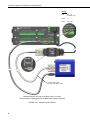
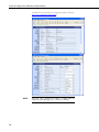
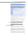
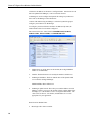
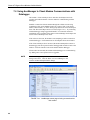
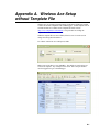
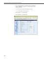
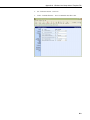
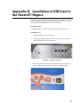
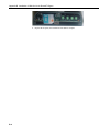
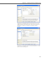
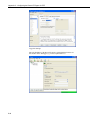
INSTRUCTION MANUAL Raven XT-Rogers Sierra Wireless Cellular Modem Dec 2011 Copyright © 2010 Campbell Scientific (Canada)Corp. WARRANTY AND ASSISTANCE This equipment is warranted by CAMPBELL SCIENTIFIC (CANADA) CORP. (“CSC”) to be free from defects in materials and workmanship under normal use and service for twelve (12) months from date of shipment unless specified otherwise. ***** Batteries are not warranted. ***** CSC's obligation under this warranty is limited to repairing or replacing (at CSC's option) defective products. The customer shall assume all costs of removing, reinstalling, and shipping defective products to CSC. CSC will return such products by surface carrier prepaid. This warranty shall not apply to any CSC products which have been subjected to modification, misuse, neglect, accidents of nature, or shipping damage. This warranty is in lieu of all other warranties, expressed or implied, including warranties of merchantability or fitness for a particular purpose. CSC is not liable for special, indirect, incidental, or consequential damages. Products may not be returned without prior authorization. To obtain a Return Merchandise Authorization (RMA), contact CAMPBELL SCIENTIFIC (CANADA) CORP., at (780) 454-2505. An RMA number will be issued in order to facilitate Repair Personnel in identifying an instrument upon arrival. Please write this number clearly on the outside of the shipping container. Include description of symptoms and all pertinent details. CAMPBELL SCIENTIFIC (CANADA) CORP. does not accept collect calls. Non-warranty products returned for repair should be accompanied by a purchase order to cover repair costs. Raven XT-Rogers Table of Contents PDF viewers note: These page numbers refer to the printed version of this document. Use the Adobe Acrobat® bookmarks tab for links to specific sections. 1. General Description.....................................................1 2. Establish Cellular Service...........................................1 2.1 Raven XT-Rogers Cellular Coverage/Service Requirements...................1 3. Specifications ..............................................................2 3.1 Raven XT-Rogers Specifications .............................................................2 4. Configuration ...............................................................3 4.1 Base Station Requirements for Raven XT-Rogers ...................................3 4.2 Datalogger Site Equipment.......................................................................3 4.3 Power Considerations ...............................................................................8 5. Program the Raven XT-Rogers Modem .....................8 5.1 Using AceManager to Configure the Modem...........................................9 5.2 Dynamic IP Address ...............................................................................11 5.3 Raven XT-Rogers Indicator Lights ........................................................14 6. LoggerNet/PC400W Software Setup ........................14 7. Troubleshooting ........................................................16 7.1 Check the Modem Configuration ...........................................................16 7.2 Verify Connections at the Datalogger ....................................................20 7.3 LoggerNet/PC400W Device Map...........................................................21 7.4 Using AceManager to Check Modem Communications with Datalogger .................................................................................................22 Appendices A. Wireless Ace Setup without Template File ........... A-1 B. Installation of SIM Card in the Raven XT-Rogers. B-1 C. Configuring the Raven for PPP.............................. C-1 i Raven XT-Rogers Table of Contents Figures 4.2-1. Modem Interface Options ................................................................. 4-6 4.2-2. Antennas for Use with the Raven Modems ......................................... 6 7.3-1. Device Port Configuration................................................................. 22 7.4-1. AceManager status page showing communications with modem ..... 23 B-1. Modem Faceplate............................................................................... B-1 ii Raven XT-Rogers Sierra Wireless Cellular Modem 1. General Description This manual provides information for interfacing the Sierra Wireless Raven XT-‐Rogers cellular modem to Campbell Scientific dataloggers. A Sierra Wireless CD ships with the modem that includes Sierra Wireless manuals and software utilities. Sierra Wireless manuals referenced in this manual include: Raven_XT_Quickstart.pdf Raven_XT_UserGuide.pdf The Raven XT-‐Rogers digital cellular modem is manufactured by Sierra Wireless for use on the Rogers General Packet Radio Service (GPRS) network. The modem is accessed through the Internet using TCP/IP communications protocol using a Static or Dynamic IP address. • A Static IP address is permanently assigned to a particular account and will always be used whenever the Raven connects to the Internet. • A Dynamic IP address is assigned on a “need to have” basis. A dynamic IP address is used with a DDNS service (Section 5) to translate a dynamic IP address to a domain name, so that the Raven can be contacted as if it had a static IP. A Rogers GPRS account can be setup for a Dynamic or static IP address. A data account with the VPN.COM APN as described in Section 2.1 is required for public access to the modem. 2. Establish Cellular Service 2.1 Raven XT-Rogers Cellular Coverage/Service Requirements What you need: Rogers GPRS coverage at the datalogger site (for a coverage map refer to: http://your.rogers.com/Store/Wireless/coverage/info.asp). GPRS account established with Rogers. Rogers will provide a SIM card for each modem. In most cases the SIM can be picked up at a local Rogers store. The SIM card must be installed inside of the modem as described in Appendix B. Contact Rogers to setup an account. Ask for an “unrestricted data account for a GPRS modem”. After the account has been setup, mobile termination will need to be configured onto the account, which is done by adding the “VPN.COM APN” to the account. Mobile termination makes the modem accessible through the internet. The APN name must be programmed into the modem as described in Section 5.1. 1 Raven XT-Rogers Sierra Wireless Cellular Modem When completed Rogers should provide you with the following information: 10-digit MSISDN number (used for billing) IP Address and APN for GPRS service 3. Specifications 3.1 Raven XT-Rogers Specifications Sierra Wireless RavenXT, model G2212-C GPRS modem Technology: GPRS (MS-12) Bands: Quadband, 1900/850 MHz and 1800/900 MHz Transmit Frequency: 1850 to 1910 MHz and 824 to 849 MHz Transmit Power: 1.0 W for 1900 MHz; 0.8 W for 850 MHz Receiver Frequency: 1930 to 1990 MHz and 869 to 894 MHz GPRS Throughput: up to 70 kbps RS-232 Data Rates: 1200 bps to 115.2 kbps Serial Interface: RS-232, DB9-F Serial Protocols: AT Commands, PPP, SLIP, UDP, TCP RF Antenna Connector: 50 Ohm SMA (female) Input Current Range: 40 to 250 mA Typical Current Drain (at 12 Vdc): 50 mA dormant (idle for 10 to 20 seconds), 120 mA transmit/receive Input Voltage Range: 6 to 28 Vdc Operating Temperature Range: -30° to +65°C 2 Operating Humidity Range: 5% to 95% RH non-condensing Status LEDs: Power, Network, Signal, Activity Dimensions: 3”W x 1”D x 4”L (7.6 x 2.5 x 10 cm) Weight: <1 lb (<0.5 kg) Raven XT-Rogers Sierra Wireless Cellular Modem 4. Configuration 4.1 Base Station Requirements for Raven XT-Rogers • A PC running Campbell Scientifics’ LoggerNet or PC400 software, with access to the internet. 4.2 Datalogger Site Equipment • Raven XT-Rogers modem with power cable (included with modem). • Datalogger—21X, CR510, CR10(X), CR23X, CR7, CR1000, CR5000, CR3000, CR800. • SC105 or SC932A Interface—connects the modem to the 21X, CR510, CR10(X), CR7, or other dataloggers’ CS I/O port. The SC105 must be configured for use with the modem using the Device Configuration Utility. Settings should be: CS I/O Mode: SDC Address 7 RS-232 Mode: Modem Baud Rate: 115.2K or 9600 baud depending on datalogger model 8 data bits, 1 stop bit, no parity • NOTE PN L18663 Null Modem Cable—connects the modem to the CR23X, CR3000, CR800, CR200-series, CR1000 or CR5000 RS-232 port. If you have a black SC12 cable that is not Rev 1 or newer (as indicated on cable), it is a CS I/O cable only and will not work for RS-232. Connect the black SC12 cable between the datalogger and the SC932A. Use a 9-pin serial cable or a blue ribbon cable between the phone and the SC932A. 3 Raven XT-Rogers Sierra Wireless Cellular Modem Wiring: Red 12V (or switched 12V) Black G White Not Used PN L18663 PN 18663 Null Modem Cable—connects the modem to the CR23X, CR3000, CR800, CR2XX, CR1000 or CR5000 RS-232 port (not compatible with the 21X, CR510, CR10X, or CR7 dataloggers). 4 Raven XT-Rogers Sierra Wireless Cellular Modem Wiring: Red 12V (or switched 12V) Black G White Not Used L10873 serial cable provided with the SC105 SC105 Settings: CS I/O Mode: SDC Address 7 RS-232 Mode: Modem Baud Rate: 115.2K or 9600 baud depending on datalogger model 8 data bits, 1 stop bit, no parity SC105 interface connects the modem to a datalogger’s CS I/O port; recommended for dataloggers with the Pakbus Operating System. 5 Raven XT-Rogers Sierra Wireless Cellular Modem Wiring: Red 12V (or switched 12V) Black G White Not Used L10873 serial cable provided with the SC932A SC932A interface connects the modem to the CS I/O port; recommended for dataloggers with the Mixed-Array Operating System. FIGURE 4.2-1. Modem Interface Options. 6 Raven XT-Rogers Sierra Wireless Cellular Modem • PN L14394 Raven Mounting Kit—includes mounting hardware for securing the modem to below referenced environmental enclosure and a 9pin male to 9-pin female cable. • Antenna—the following antennas are available from Campbell Scientific. Contact a Campbell Scientific Applications Technician for help in determining the best antenna for your application. o The C2446 is a dual-band, omnidirectional antenna for our digital-cellular modems. This antenna is recommended for locations where cellular coverage is strong. The C2446 includes a mount/u-bolt assembly that allows the antenna to be mounted to a mast, crossarm, or user-supplied pole (outer diameter of up to 1.5" (3.8 cm)). o The L18285 1 dBd omnidirectional antenna. This antenna is dual band, covering both the 800 MHz and 1.9 GHz bands, and is strongly recommended where cellular coverage is strong. The L18285 includes a mount/u-bolt assembly for attaching the antenna to a mast, post, or crossarm up to 1.5" (3.8 cm) in diameter. o The C2445 9dBd Yagi Antenna is a higher gain antenna that should be "aimed" at the service provider's antenna. The C2445 is an 800 MHz antenna and bracket/u-bolt assembly for attaching the antenna to a mast or post. The antenna comes with 10’ of cable. This antenna is recommended for fringe areas that require a higher gain antenna. o The L21831 Half-Wave Dipole Whip Antenna is a lower gain antenna used in transmitting short distances. It is an 800 MHz cellular antenna that terminates in a SMA Male connector for attachment to the modem. This antenna is intended for use inside the enclosure. Please note that the backplate of the enclosure is a grounded plane. If it is interposed between the antenna and the cell tower, it may attenuate the strength of the transmission signal. Simply turning the enclosure 90 to 180 degrees on its mounting mast may solve weak transmission issues. PN L18285 1 dBd Omni Directional Antenna 7 Raven XT-Rogers Sierra Wireless Cellular Modem PN C2445 9dBd Directional Yaggi Antenna PN L21831 Half-Wave Dipole Whip Antenna FIGURE 4.2-2. Antennas for Use with the Raven Modems • Power Supply (see power considerations). • Environmental Enclosure— ENC 10/12, ENC 12/14, or ENC 16/18. 4.3 Power Considerations • A power cable included with the modem connects to the datalogger's 12 V or switched 12 V terminal. Connection to the switched 12 V terminal allows the datalogger to switch power to the modem during scheduled transmission intervals if desired. • When using the switched 12 V terminal, the modem can typically be powered with a BP12 battery, CH100 charger/regulator, and MSX10 solar panel. 5. Program the Raven XT-Rogers Modem It is recommended that the modem be provisioned and tested in the office (assuming there is cellular coverage) rather than in the field. The AceManager software utility is used to configure settings in the modem and to load the Raven XT template file. The AceManager utility can be found on the CD included with the modem, or can be downloaded from Sierra Wireless’s website: www.SierraWireless.com/support. Campbell Scientific’s “Raven XT Template 115200” file for dataloggers that support 115200 baud (e.g. CR1000), or “Raven XT Template 9600” file for dataloggers that support a maximum baud rate of 9600 (e.g. CR10X). The template file configures the modem to be compatible with CSI dataloggers. 8 Raven XT-Rogers Sierra Wireless Cellular Modem The template files are available from Campbell Scientific’s Website: http://www.campbellsci.ca/download. 5.1 Using AceManager to Configure the Modem To install AceManager from the Sierra Wireless CD, click on the “AceManager” link under “Modem Utilities” and follow the prompts. Once the application has been installed, it can be run from the Windows Start menu or from the icon on the desktop. Connect the Raven XT-Rogers to a serial RS232 port on the PC with a direct RS-232 cable. Also connect the antenna, and 12 V power. Run AceManager to get the following screen: Click the Connect icon in the Configuration Panel to open the connection options dialogue box. Select PPP, and the COM port the modem is connected to. Do not change the Password (the default password is 12345). Click OK to continue. If the modem has been configured for “PPP” (see appendix B), then you may have to check the “Use SOS Mode” box. Click the Load icon in the Configuration panel. When prompted for a template file name, select the appropriate .xml file for the datalogger that you are using. The template file configures the modem to be compatible with CSI dataloggers. 9 Raven XT-Rogers Sierra Wireless Cellular Modem Template files are available from Campbell Scientific’s Website: http://www.campbellsci.ca/download. NOTE 10 Baud rate can be changed from 9600, to a higher baud rate supported by the datalogger (e.g., 115200 for a CR1000). Raven XT-Rogers Sierra Wireless Cellular Modem Click on EDGE/HSDPA Group to get the following screen: For a data account with the VPN.COM APN, enter the APN as shown in the following screen. The example is for an APN = “I2GOLD.COM”. After the template file has been loaded, and the APN entered, click the Write icon to save the changes in the modem. Click the Reset icon to restart the modem. The other ways to reset the modem are by pressing the reset button on the front of the modem or removing the power from the modem. Click the Disconnect icon to terminate communications with the modem. NOTE Unless you click the Write command, changes made in the New Value field will not be sent to the modem. For some changes (e.g., baud rate) you must also Reset the modem before the changes will take effect. 5.2 Dynamic IP Address Dynamic IP addresses are granted only when a modem or other device is connected and can change each time the modem or device reconnects to the network. IP Manager is a free service provided by Sierra Wireless for the Raven to translate a dynamic IP address into a fully qualified domain name so it can be contacted directly on the Internet. IP Manager translates a dynamic IP address to a fully qualified domain name so you can contact your Raven by name as if it had a static IP. If the Raven is configured for Dynamic IP, when the Raven first connects to the Internet, it sends an IP change notification to IP Manager. IP Manger will acknowledge the change and update the DNS record. The changed IP address 11 Raven XT-Rogers Sierra Wireless Cellular Modem will then be the address for the Raven’s configured name. Once the Raven’s IP has been updated in IP Manager, it can be contacted via name. AceManager is used to configure the Dynamic IP settings in your Raven so that it will use IP Manager as described below. Connect with modem using AceManager. Select the Dynamic IP group to configure your modem to use IP Manager. To configure your Sierra Wireless modem to be addressed by name, the modem needs to have four elements configured. Enter names in the New Value fields for MODEMNAME, DOMAIN, IPMANAGER1, IPMANAGER2, and IPMGRUPDATE1. 1. Modem name: A unique name for the modem (the 10-digit MSISDN number is recommended). 2. Domain: The domain name to be used by the modem (eairlink.com). 3. IP Manager IP Address: The IP or domain name of the dynamic DNS server which is running IP Manager. IPMANAGER1: edns2.eairlink.com IPMANAGER2: edns2.eairlink.com 4. IP Manager update interval: How often you want the address sent to IP Manager. If this is set to zero, the modem will only send an update if the IP changes (i.e. if the modem is reset or is assigned a different IP). The value can be set from 0 - 255 minutes, and should be set to a value appropriate for your application. Restrictions for Modem Name • 12 Must begin with a letter or number Raven XT-Rogers Sierra Wireless Cellular Modem • Can include a hyphen (-) • Cannot contain spaces • Must be no longer than 20 characters total Click the Write icon to save the changes. Click the Reset icon to restart the modem. Click the Disconnect icon to terminate communications with the modem. 5.3 Raven XT-Rogers Indicator Lights When your Raven XT-Rogers is connected to power and an antenna, there is a specific pattern to the lights to indicate its operation mode. • Network—Indicates a successful connection to the cellular network with an IP address given and a channel acquired. • Signal—Light shows the strength of the signal and may be nearly solid (strong signal) or flashing (weaker signal). A slow flash indicates a very weak signal. • Activity—Lights will flash as data is transferred to and from the modem on the remote network. • Power—Indicates the power adapter is connected and there is power getting to the Raven XT-Rogers. • The Reset button (on the left side of the Raven XT) has two functions. If it is quickly depressed and released, the modem will simply power cycle the internal hardware. If, however, the reset is depressed and held for several seconds (count 10 slowly, and wait for the power light to go off after the light pattern stops), the ALEOS configuration settings will return to the factory defaults. 13 Raven XT-Rogers Sierra Wireless Cellular Modem Light Patterns The LEDs on the front of the modem will respond in different patterns to indicate modem states. • Normal—Each LED, mentioned above, lit as applicable. • Start up—The LEDs will cycle from left to right. • PassThru mode—Network and Signal LEDs will blink in tandem. The Activity LED will blink when transmitting or receiving data. • SOS—The Network LED blinks. • Configuration Reset—The LEDs will cycle left to right and then right to left 4 times. • Authentication Failure—The Network, Signal, and Activity LEDs blink every 2 seconds. • Data Retry—The Network, Signal, and Activity LEDs blink every 3 seconds. 6. LoggerNet/PC400W Software Setup The Device Map is configured from the “Setup” button on the LoggerNet/PC400W Toolbar. Configure the Device Map as described below. 14 1. Selet Add Root | IPPort. 2. Add a datalogger to the IPPort (Pakbus dataloggers, e.g. the CR1000, require a PakBusPort). 3. On the IPPort page, add the IP address or fully qualified domain name as setup in Section 5.2 and the Port number (the Raven template file configures the port to be 6785). Add four seconds of extra response time. 4. For PakBus dataloggers, leave the default settings on the PakBusPort page. 5. For PakBus dataloggers, set the PakBus address to match that of the datalogger (default address in the datalogger is 1). Make sure that “PakBus Port Always Open” is unchecked. Raven XT-Rogers Sierra Wireless Cellular Modem LoggerNet Device Map For a Dynamic IP using Sierra Wireless’s IP Manager (Section 5.2), enter the internet IP address as: xxxx.yyyy:6785, where xxxx is the modem name, yyyy is the Domain name, and 6785 is the port number. Uncheck “Pakbus Port Always Open”. Enter Pakbus address that has been set in the datalogger (default is 1). 15 Raven XT-Rogers Sierra Wireless Cellular Modem In some cases where signal strength is low, you may have to decrease the packet size of the CR1000. A recommended value of 400 bytes should be sufficient. 7. Troubleshooting If LoggerNet/PC400W software is unable to establish a connection with the modem: 7.1 Check the Modem Configuration 16 a. Check the GPRS cellular account information, and verify there is GPRS coverage at the site. Dynamic IP accounts require a Dynamic Domain Name Server (DDNS) (Section 5). b. The modem has to be configured using AceManager as described in Section 5. c. Modem settings have to be changed, and the APN entered, using AceManager (Section 5). After the Raven XT template file has been loaded, you can verify settings in the Status, Misc, Serial, and GPRS/EDGE groups have been configured as shown below. Raven XT-Rogers Sierra Wireless Cellular Modem The Device Port gets changed from the default 12345 to 6785 when the template file is loaded into the modem (Section 5). The Device Port number gets entered with the IP address in LoggerNet (Section 6). 17 Raven XT-Rogers Sierra Wireless Cellular Modem Connect to the modem with AceManager (Section 5.3). Select the “Serial” Group, and make sure the “AT Verbose Mode” is set to “Numeric” for use with the CR10(X), CR510, and CR23X dataloggers, or “Verbose” for other dataloggers (e.g. CR1000). The “Raven XT Template 9600” template file sets the baud rate to 9600, which is the maximum baud rate for the CR10X and older dataloggers. For newer dataloggers, the baud rate can be changed to the highest baud rate supported by the datalogger (e.g. 115200 baud for the CR1000). NOTE 18 Baud rate changes require the modem to be reset before the change takes affect. Click the Reset icon in AceManager to the reset the modem and implement the change. Raven XT-Rogers Sierra Wireless Cellular Modem Verify the APN has been entered in the NETAPN and +CGDCONT fields as shown above (where VPN.COM is the APN). d. If an SC105 interface is used, its default baud rate of 9600 will have to be changed to match the baud rate of the modem (using CSI’s DevConfig utility). e. Check the Network light. Network – indicates a successful connection to the cellular network with an IP Address given and a channel acquired. f. Make sure the modem has sufficient power. g. Check the signal strength (make sure your antenna is properly connected and oriented). Signal strength should be in the -51 to -90 range (-51 is a strong signal, -90 is a weak signal). h. If you have a Static IP account, verify the Static IP Address. Preceding zeros in the IP address are not entered in LoggerNet/PC400W. i. If you have a Dynamic IP account, you will need to have a DDNS (dynamic domain name server) name that LoggerNet can reference to make the connection (Section 5). j. Connect with the modem through the serial port using AceManager. If the modem has been configured for “PPP” (see appendix B), then you may have to check the “Use SOS Mode” box. From the “Status” group, make sure the “Network State” is “Network Ready”, and note the “Network IP” address. This is the current IP address for the modem (a dynamic IP address may change when the modem is reset). Try connecting to this IP address using LoggerNet. If LoggerNet connects with the IP address, but not with the modem name.domain name, then there may be a problem with the Dynamic IP setup in the modem (Section 5). 19 Raven XT-Rogers Sierra Wireless Cellular Modem 7.2 Verify Connections at the Datalogger Verify the modem is connected to 12 V and the power led is on (green). Check the Network light on the modem. The Network light should be solid green, which indicates the modem is registered with the cellular network. Make sure the antenna is properly connected and oriented. Signal strength should be the -60 to -80. An SC932A or SC105 interface is required to connect the modem to a datalogger’s CSI/O port. The default settings for SC105 (OS > 4) can be used with the Raven XT-Rogers when the modem is configured for 115200 baud (baud rate set by the template file). If the baud rate is changed in the modem, the baud rate in the SC105 will have to be changed to match that of the modem (settings can be changed using CSI’s DevConfig utility). Make sure the modem is connected to the “DCE Device” connector on the SC932A, or the “Modem” connector on the SC105. A null modem cable is required to connect the modem to a datalogger’s RS-232 port. No other interface is required. 20 Raven XT-Rogers Sierra Wireless Cellular Modem 7.3 LoggerNet/PC400W Device Map Check your LoggerNet setup. a. Make sure the port number at the end of the IP address matches the port number of the Raven (e.g. 6785, see Figure 7.3-1). FIGURE 7.3-1. Device Port Configuration b. Try adding a few seconds to the extra response time on the IP Port in LoggerNet (you should not need more than 5 seconds). c. If you are trying to communicate to a PakBus datalogger: i. Verify the PakBus address in the setup screen matches that of the datalogger. ii. If you have multiple PakBus networks/ports setup in LoggerNet, uncheck the ‘PakBus Port Always Open’ options on all PakBus ports. 21 Raven XT-Rogers Sierra Wireless Cellular Modem 7.4 Using AceManager to Check Modem Communications with Datalogger The modem’s “Host Serial Bytes Sent” and “Host Serial Bytes Received” windows can indicate whether or not the modem is communicating with the datalogger. Establish a connection with the modem through the cellular network using AceManager (click on the Modem menu item, Connect, UDP. Enter the IP address, and click OK). Go to the Status group and note the “Host Serial Bytes Sent” and “Host Serial Bytes Received” values (Figure 7.4-1). Try connecting with the datalogger using LoggerNet/PC400W. If a connection cannot be established, close LoggerNet and reconnect with AceManager and compare the current values with the previous values. If the values are the same, the modem is not attempting to make a connection with the datalogger. Check that the Raven XT template file has been loaded. If the “Host Serial Bytes Sent” increased, the modem attempted to connect to the datalogger, but the response from the datalogger did not make it back to the modem. Check the interface between the modem and the datalogger. If both values incremented, the modem and the datalogger are communicating. Try adding some extra response time in LoggerNet. NOTE Baud rate changes require the modem to be reset before the change takes affect. Click the Reset icon in AceManager to the reset the modem and implement the change. FIGURE 7.4-1. AceManager status page showing communications with modem. 22 Appendix A. Wireless Ace Setup without Template File Wireless Ace 3G is used to program settings in the Raven XT-Rogers modem to make the modem compatible with CSI dataloggers. Airlink template files to send the modems are available on the Campbell Scientific website (http://www.campbellsci.ca/download). The procedure for sending the template files is described in Section 5. When the template files are not available, Wireless Ace 3G can be used to change the settings described below. For a direct connection on a COM port use PPP. Make a note of the Device port (*DPORT). The default is 12345 and we use 6785 in our template. Any valid port can be used. This is the port number used in LoggerNet to get to the datalogger. A-1 Appendix A. Wireless Ace Setup without Template File A-2 • S23 – Configure Serial Port – The baud rate needs to be configured to match a valid datalogger baud rate. For a CR10X: 9600,8N1 and for a CR1000: 115200,8N1. • \Q – Serial Port Flow Control – This should be set to None. • V – AT Verbose Mode – Set this to Numeric. • &D – DTR Mode – Set to Ignore DTR • S211 – DTR Mode – Set to Ignore DTR Appendix A. Wireless Ace Setup without Template File • S0 – TCP Auto Answer – Set to On • TCPT – TCP Idle Timeout -- Set to a reasonable value like 2 min. A-3 Appendix A. Wireless Ace Setup without Template File This is a blank page. A-4 Appendix B. Installation of SIM Card in the RavenXT-Rogers The Subscriber Identity Module (SIM) in the Raven XT-Rogers is a smartcard securely storing the key identifying a mobile subscriber. Generally, you will only need to install the SIM once in the life of the modem. Installing the SIM To install the SIM, you will only need a small Phillips head screw driver. Opening the Case 1. Unplug the modem power and all cables. 2. Using a small Phillips head screw driver, remove the two screws on the back of the modem, set the faceplate aside. FIGURE B-1. Modem Faceplate 3. Remove the SIM from the card you obtained from Rogers, and gently press the SIM card to secure in place as shown in the figure below. B-1 Appendix B. Installation of SIM Card in the RavenXT-Rogers 4. B-2 Replace the faceplate; the installation of the SIM is complete. Appendix C. Configuring the Raven XTRogers for PPP The Raven XT-Rogers template file configures the Raven XT-Rogers to function as a serial server. As a serial server, the modem has an IP address, and port number (6785) for the Raven XT-Rogers’ RS232 port. LoggerNet sends data via TCP/IP over the internet to the datalogger. The modem removes the data from the TCP packet and sends the data out the RS232 port to the datalogger. Returning data is put into a TCP packet by the modem and sent back to LoggerNet. Settings in the Raven XT-Rogers and datalogger (CR800, CR1000, and CR3000) can be changed to configure the RS232 serial ports for Point-to-Point (PPP) protocol. When configured as PPP, the Raven XT-Rogers functions as a router, routing TCP/IP communications to the IP stack of the datalogger. PPP enables the datalogger to send/receive messages via email, HTTP, FTP to and from the datalogger, and allows concurrent communications between networked dataloggers and LoggerNet. The default datalogger port number for PakBus/TCP communications is 6785. The datalogger will also respond to port 80 for HTTP, 23 for Telnet and 21 for FTP. These ports can be disabled in the dataloggers configuration. NOTE After the RS232 port on the modem has been configured as PPP, use Wireless Ace 3G with a TCP or UDP connection to establish communications with the modem. It may also be possible to connect with the modem through its RS232 port using the “SOS” mode. Raven XT-Rogers Settings for PPP Mode: Download the current Raven XT-Rogers AceManager template file from http://www.campbellsci.ca/download. Load the template into AceManager and make the following changes in steps 1 and 2 before writing them to the Raven XT-Rogers modem. C-1 Appendix C. Configuring the Raven XT-Rogers for PPP Use AceManager to configure the following Misc setting: • DPort = 3001 (Changed from 6785) This setting change allows information to be passed from loggernet to the the Datalogger. If we were to leave the DPort setting at 6785 the Raven XT-Rogers would trap the information as its own and Loggernet will show an error of “Connection Refused” when you try to connect to the Datalogger. Ensure that the Loggernet port setting is left as 6785, so that the modem will function in PPP mode. Use AceManager to configure the following UDP setting: • MD = 02-PPP (Changed from 00 — Normal, AT command) After the changes have been made, click the Write icon to save the changes in the modem. Click the Reset icon to restart the modem. The other ways to reset the modem are by pressing the reset button on the front of the modem or removing the power from the modem. Click the Disconnect icon to terminate communications with the modem. Datalogger Settings: Using the Device Configuration Utility, configure the following setting on the TCP/IP tab: • • • • • C-2 Config Port Used = RS232 IP Address = 0.0.0.0 Modem Dial String = PPP Modem Dial Response = CONNECT User Name and Password are blank Appendix C. Configuring the Raven XT-Rogers for PPP Using the Device Configuration Utility, select the “Net Services” tab. The “PakBus/TCP Service Port” default is 6785. This is the “Port” number that will follow the “IP address” for LoggerNet to communicate with the datalogger. Using the Device Configuration Utility, fix the RS232 Baud Rate to “115200 Fixed” from the “Port Settings” tab. C-3 Appendix C. Configuring the Raven XT-Rogers for PPP LoggerNet Settings: Enter the IP address of the Raven XT-Rogers, and the PakBus/TCP Service Port number of the datalogger (e.g. 6785 as explained above). C-4 Appendix C. Configuring the Raven XT-Rogers for PPP Example CR1000 Program The following example sends an email message when an alarm condition is True. Both the CR1000 and Raven XT-Rogers modem must be configured as PPP as described above. CR1000 Program Example to Send Email Message 'Main program variables Public Batt, RefTemp, Temp 'declare Email parameter strings (as constants), Message String & Result Variable Const ServerAddr="smtpauth.earthlink.net"'"207.69.189.201" Const ToAddr="[email protected]" Const FromAddr="[email protected]" Const Subject="Email Message Test" Const Attach="" Const UserName="[email protected]" Const Password="cr1000" Const CRLF = CHR(13)+CHR(10) Public Result as String * 100 Public AlarmTrigger As Boolean Public Message As String * 250 Public EmailSuccess As Boolean BeginProg Scan (1,Sec,3,0) Battery (Batt) PanelTemp (RefTemp,250) TCDiff (Temp,1,mV2_5C,1,TypeT,RefTemp,True ,0,250,1.0,0) NextScan SlowSequence Scan(1,sec,1,0) If AlarmTrigger = False Then If Temp > 28 THEN AlarmTrigger = True If AlarmTrigger Then Message = "Warning!" + CRLF + CRLF Message = Message + "This is a automatic email message from the datalogger station " + Status.StationName + ". " Message = Message + "An alarm condition has been identified. " Message = Message + "The temperature is " + Temp + " degrees C." + CRLF + CRLF + CRLF Message = Message + "Datalogger time is " + Status.Timestamp EmailSuccess=EmailSend (ServerAddr,ToAddr,FromAddr,Subject,Message,Attach,UserName,Password,Result) EndIf EndIf If Temp < 28 then AlarmTrigger=False NextScan EndProg C-5 Appendix C. Configuring the Raven XT-Rogers for PPP This is a blank page. C-6