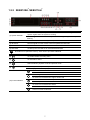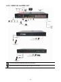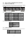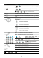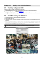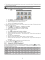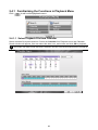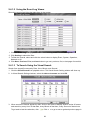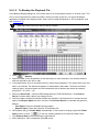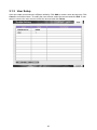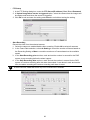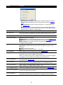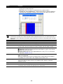
1
SEB5108H Lite SEB5116H Lite SEB5108H+ SEB5116H+ Sept. 2010 FCC NOTICE (Class A) This device complies with Part 15 of the FCC Rules. Operation is subject to the following two conditions: (1) this device may not cause harmful interference, and (2) this device must accept any interference received, including interference that may cause undesired operation. Federal Communications Commission Statement NOTE- This equipment has been tested and found to comply with the limits for a Class A digital device, pursuant to Part 15 of the FCC Rules. These limits are designed to provide reasonable protection against harmful interference in a residential installation. This equipment generates uses and can radiate radio frequency energy and, if not installed and used in accordance with the instructions, may cause harmful interference to radio communications. However, there is no guarantee that interference will not occur in a particular installation. If this equipment does cause harmful interference to radio or television reception, which can be determined by tuning the equipment off and on, the user is encouraged to try to correct the interference by one or more of the following measures: Reorient or relocate the receiving antenna. Increase the separation between the equipment and receiver. Connect the equipment into an outlet on a circuit different from that to which the receiver is connected. Consult the dealer or an experienced radio/television technician for help. Class A ITE Class A ITE is a category of all other ITE which satisfies the class A ITE limits but not the class B ITE limits. Such equipment should not be restricted in its sale but the following warning shall be included in the instructions for use: Warning -This is a class A product. In a domestic environment this product may cause radio interference in which case the user may be required to take adequate measures. European Community Compliance Statement (Class A) This product is herewith confirmed to comply with the requirements set out in the Council Directives on the Approximation of the laws of the Member States relating to Electromagnetic Compatibility Directive 2004/108/EC. Warning - This is a Class A product. In a domestic environment this product may cause radio interference in which case the user may be required to take adequate measures to correct this interference. DISCLAIMER No warranty or representation, either expressed or implied, is made with respect to the contents of this documentation, its quality, performance, merchantability, or fitness for a particular purpose. Information presented in this documentation has been carefully checked for reliability; however, no responsibility is assumed for inaccuracies. The information contained in this documentation is subject to change without notice. In no event will AVerMedia be liable for direct, indirect, special, incidental, or consequential damages arising out of the use or inability to use this product or documentation, even if advised of the possibility of such damages. TRADEMARKS "AVerMedia" is a trademark (or registered trademark) of AVerMedia Technologies, Inc and has been authorized AVerMedia Information Inc to use. Other trademarks used herein for description purpose only belong to each of their companies. COPYRIGHT © 2009-2010 by AVerMedia Information, Inc. All right reserved. No part of this document may be reproduced or transmitted in any form, or by any means without the prior written permission of AVerMedia Information Inc. AVerMedia Information Inc. reserves the right to modify its models, including their characteristics, specifications, accessories and any other information stated herein without notice. The official printout of any information shall prevail should there be any discrepancy between the information contained herein and the information contained in that printout. The mark of Crossed-out wheeled bin indicates that this product must not be disposed of with your other household waste. Instead, you need to dispose of the waste equipment by handing it over to a designated collection point for the recycling of waste electrical and electronic equipment. For more information about where to drop off your waste equipment for recycling, please contact your household waste disposal service or the shop where you purchased the product. Battery Safety Information - Store the batteries in a cool dry place. Do not dispose of used batteries in domestic waste. Dispose of batteries at special collection points or return to point of sale if applies. Remove the batteries during long periods of non-use. Always remove exhausted batteries from the remote control. Battery leakage and corrosion can damage this remote control, dispose of batteries safely. Do not mix old and new batteries. Do not mix different types of batteries: alkaline, standard (carbon-zinc) or rechargeable (nickel-cadmium). Do not dispose of batteries in a fire. The batteries may explode or leak. Never short circuit the battery terminals. WARNING TO REDUCE RISK OF FIRE OR ELECTRIC SHOCK, DO NOT EXPOSE THIS APPLIANCE TO RAIN OR MOISTURE CAUTION IF THERE IS ANY DAMAGE, SHORTAGE OR INAPPROPRIATE ITEM IN THE PACKAGE, PLEASE CONTACT WITH YOUR LOCAL DEALER. WARRANTY VOID FOR ANY UNAUTHORIZED PRODUCT MODIFICATION NOTICE - INFORMATION IN THIS DOCUMENT IS SUBJECT TO CHANGE WITHOUT NOTICE. - THE INFORMATION CONTAINED HEREIN IS TO BE CONSIDERED FOR REFERENCE ONLY. Table of Contents Chapter 1 Introduction .............................................................................. 1 1.1 Package Content .................................................................................................. 1 1.1.1 SEB5108H Lite ................................................................................................ 1 1.1.2 SEB5108H+ ...................................................................................................... 2 1.1.3 SEB5116H Lite ................................................................................................. 3 1.1.4 SEB5116H+ ...................................................................................................... 4 1.1.5 Optional Accessories ....................................................................................... 5 1.2 Front Panel ........................................................................................................... 6 1.2.1 SEB5108H/SEB5116H Lite .............................................................................. 6 1.2.2 SEB5108H+/SEB5116H+ .................................................................................. 7 1.2.2.1 To Set a Video Segment and Save ............................................................ 9 1.3 Back Panel ......................................................................................................... 10 1.3.1 SEB5108H Lite/SEB5108H+ .......................................................................... 10 1.3.2 SEB5116H Lite/SEB5116H+ ............................................................................ 11 1.4 Setting Up the DVR Unit ..................................................................................... 12 1.4.1 Installing the Hard Disk .................................................................................. 12 1.4.2 Connecting Devices ....................................................................................... 15 1.4.2.1 SEB5108H Lite/SEB5108H+ .................................................................... 15 1.4.2.2 SEB5116H Lite/SEB5116H+..................................................................... 16 1.5 Sensor, Relay and RS485 pinhole allocation...................................................... 17 1.5.1 SEB5116H Lite/SEB5116H+ ........................................................................... 17 1.5.1.1 Sensor Pin Definition ............................................................................... 17 1.5.1.2 Relay Pin Definition ................................................................................. 17 1.5.1.3 RS485 Pin Definition................................................................................ 17 1.5.2 SEB5108H Lite/SEB5108H+ .......................................................................... 18 1.5.2.1 Sensor Pin Definition ............................................................................... 18 1.5.2.2 Relay Pin Definition ................................................................................. 18 1.5.2.3 RS485 Pin Definition................................................................................ 18 1.6 Familiarizing the Remote Control Buttons .......................................................... 19 Chapter 2 Using the DVR Software ......................................................... 21 2.1 2.2 The Way to Operate DVR ................................................................................... 21 First Time Using the DVR Unit ............................................................................ 21 2.2.1 Using the Virtual Keyboard ............................................................................ 22 2.3 Familiarizing the Functions in Preview Mode ..................................................... 23 2.3.1 Using the PTZ Control Panel ......................................................................... 24 2.3.1.1 Familiarizing the Buttons in PTZ Control Panel ....................................... 25 2.4 Familiarizing the Functions in Playback Mode .................................................... 26 2.4.1 Familiarizing the Functions in Playback Menu ............................................... 28 2.4.1.1 Select Playback File from Calendar ......................................................... 28 2.4.1.2 Using the Event Log Viewer..................................................................... 29 2.4.1.3 To Search Using the Visual Search ......................................................... 29 2.4.1.4 To Set a Video Segment and Save .......................................................... 30 2.4.1.5 To Backup the Playback File .................................................................... 31 2.5 Playback Backup Video ...................................................................................... 32 Chapter 3 Customizing the DVR System................................................ 35 3.1 System Setup ..................................................................................................... 35 3.1.1 System Setup................................................................................................. 35 3.1.2 Network Setup ............................................................................................... 40 3.1.3 User Setup ..................................................................................................... 43 3.2 Camera Setup .................................................................................................... 46 3.2.1 Camera Setting .............................................................................................. 46 3.2.2 Motion and Mask Setting................................................................................ 47 3.2.3 PTZ Camera Setting ...................................................................................... 48 3.3 Recording Setup ................................................................................................. 50 3.4 Schedule Setting ................................................................................................ 52 3.4.1 Setup System Schedule ................................................................................. 52 3.4.2 Setup Recording Schedule ............................................................................ 53 3.4.3 Setup Holiday Schedule ................................................................................. 54 3.5 Backup Setup ..................................................................................................... 56 3.6 Alarm Setting ...................................................................................................... 58 3.7 System Status Viewing ....................................................................................... 64 Chapter 4 Using the USB Playback Console ......................................... 65 4.1 4.2 Recommended system requirements ................................................................. 65 Installing the USB Playback Console ................................................................. 65 4.3 Running the USB Playback Console .................................................................. 66 4.3.1 To Cut and Save the Portion of the Recorded Video ...................................... 68 4.3.2 Playback DVR Recorded File from Hard Disk ................................................ 68 4.3.3 Playback Backup File(*.dvr) ........................................................................... 69 4.3.4 To Backup Recorded File ............................................................................... 70 4.3.5 To Search Using the Visual Search ................................................................ 71 4.3.6 To Search Using the Event Search ................................................................ 71 4.3.7 To Search Using the Intelligent Search .......................................................... 72 Chapter 5 iEnhance ................................................................................. 73 5.1 To Use iStable .................................................................................................... 74 Chapter 6 Using the Remote Programs ................................................. 75 6.1 Familiarizing the WebViewer Buttons ................................................................. 77 6.1.1 To Setup Remote System Setting .................................................................. 79 6.1.1.1 System Setup .......................................................................................... 79 6.1.1.2 Camera Setup.......................................................................................... 80 6.1.1.3 Record Setup ........................................................................................... 81 6.1.1.4 Alarm Setup ............................................................................................. 83 6.1.1.5 Network Setup ......................................................................................... 88 6.2 Familiarizing the WebViewer PTZ Buttons ......................................................... 90 6.3 Familiarizing the Remote Console Buttons......................................................... 91 6.3.1 To Setup Remote Console Setting ................................................................. 93 6.4 Using the Remote Playback ............................................................................... 94 6.4.1 Familiarizing the Local Playback Buttons ....................................................... 96 6.4.1.1 To Cut and Save the Wanted Portion of the Recorded Video .................. 98 6.4.1.2 To Search Using the Visual Search ......................................................... 99 6.4.1.3 To Search Using the Intelligent Search .................................................. 100 6.4.2 Familiarizing the Download and Playback Buttons ...................................... 101 6.4.3 Familiarizing the Realtime Playback Buttons ............................................... 103 Appendix A Registering Domain Name .................................................................... 105 Appendix B Network Service Port ............................................................................ 106 Appendix C Installing 3rd and 4th Hard Disk .............................................................. 107 Appendix D Pin definition of audio in port.................................................................. 111 Chapter 1 1.1 Introduction Package Content 1.1.1 SEB5108H Lite (3) (1) (4) (7) (2) (5) (6) (8) (1) SEB5108H Lite unit (2) Quick Installation Guide (3) Software CD (User Manual included) (4) Power adaptor (5) Power Cord * The power cord varies depending on the standard power outlet of the country where it is sold. (6) SATA cable x 2 (7) Screws for HDD installation (8) AVerMedia USB optical mouse DO NOT install more than 2 HDD with current power adaptor. It may cause unexpected damage. For additional HDD support, please contact your vendor to purchase an additional power adaptor. 1 1.1.2 SEB5108H+ (1) (3) (2) (5) (4) (6) (8) (7) + (1) SEB5108H unit (2) Quick Installation Guide (3) Software CD (User Manual included) (4) Power adaptor (5) Power Cord * The power cord varies depending on the standard power outlet of the country where it is sold. (6) SATA cable x 2 (7) Screws for HDD installation (8) AVerMedia USB optical mouse DO NOT install more than 2 HDD with current power adaptor. It may cause unexpected damage. For additional HDD support, please contact your vendor to purchase an additional power adaptor. 2 1.1.3 SEB5116H Lite (3) (1) (4) (7) (2) (5) (6) (8) (1) SEB5116H Lite unit (2) Quick Installation Guide (3) Software CD (User Manual included) (4) Power adaptor (5) Power Cord * The power cord varies depending on the standard power outlet of the country where it is sold. (6) SATA cable x 2 (7) Screws for HDD installation (8) AVerMedia USB optical mouse DO NOT install more than 2 HDD with current power adaptor. It may cause unexpected damage. For additional HDD support, please contact your vendor to purchase an additional power adaptor. 3 1.1.4 SEB5116H+ (1) (3) (2) (5) (4) (6) (8) (7) + (1) SEB5116H unit (2) Quick Installation Guide (3) Software CD (User Manual included) (4) Power adaptor (5) Power Cord * The power cord varies depending on the standard power outlet of the country where it is sold. (6) SATA cable x 2 (7) Screws for HDD installation (8) AVerMedia USB optical mouse DO NOT install more than 2 HDD with current power adaptor. It may cause unexpected damage. For additional HDD support, please contact your vendor to purchase an additional power adaptor. 4 1.1.5 Optional Accessories Audio cable for SEB5116H series Remote control Audio cable for SEB5108H series (Red cable: 8CH audio in White cable: 1CH audio out Black cable: 1CH MIC in) DVI cable for SEB5116H series only (16CH Loop out) 90W Power Adaptor th (Included HDD Holder for 4 HDD and SATA Cable) 5 (Red cable: 16CH audio in White cable: 1CH audio out Black cable: 1CH MIC in) Rack ears 1.2 Front Panel 1.2.1 SEB5108H/SEB5116H Lite Name Function (1) System Power indicator System power status indicators. Indicate running state of system. Lights when the system is running. (1) HDD indicator When DVR system is recording, the light will keep flashing. (3) Power ON/OFF DVR unit (4) IR Sensor Receive signal from the remote control to operate the DVR unit (5) IR Sensor port For extended IR sensor cable connection(optional) (6) USB 2.0 port 2 x USB 2.0 ports for connecting USB device, ex: USB pen drive, external hard disk, mouse…and so on. i The USB storage device must be in FAT32 format. 6 1.2.2 SEB5108H+/SEB5116H+ Name (1) System indicator Function Power indicator: System power status indicators. Indicate running state of system. Lights when the system is running. Recording indicator: When DVR system is recording, the light will keep flashing. (2) IR Sensor port For extended IR sensor cable(optional) (3) IR Sensor Receive signal from the remote control to operate the DVR unit (4) Power ON/OFF DVR unit (5) DVD+RW To backup the recorded file to DVD±R/DVD±RW disk i DVD+RW is an optional accessory. User need to purchase additional. (6) To enable/ disable recording video (7) To reset alarm status (8) Switch between playback mode and preview mode (9) Call out system setup menu on preview mode Call out playback menu on playback mode Move to left direction on menu control To move PTZ camera lens to left in PTZ mode Move to right direction on menu control To move PTZ camera lens to right in PTZ mode (10) Control Buttons To move PTZ camera lens to up Move to up direction on menu control To move PTZ camera lens to down Move to down direction on menu control Confirm or make a selection 7 Name Function - Channel camera selection number in playback and preview mode. For the channel over 10, press , then press ~ - ~ Press button can switch to different screen display modes ( ~ ). - Press and number button, to set the preset position in the PTZ mode. A functional key for multiple system control. Press enable multiple function modes and the (11) Number buttons light up blue. again. to button will To exit multiple function modes, press + : Switch to single screen display mode + : Switch to QUAD display mode + : Switch to 9 spilt screen display mode + : Switch to 16 split screen display + : Switch to one single and 7 + 1 spilt mode screen display mode + : Switch to one single and 12+ 1 spilt screen display mode + (12) USB 2.0 port : Enable/disable channel auto switch cycle 2 x USB 2.0 ports for connecting USB device, ex: USB pen drive, external hard disk, mouse…and so on. (13) To playback video at faster speed (14) To pause playback To start playback (15) To rewind the recorded video (16) Set a video segment to playback repeat(see also Chapter 1.2.2.1) (17) To backup recorded video file to USB storage device(pen drive or external hard disk) and DVD-ROM. 8 Name Function Operate the PTZ cameras automatically based on the selected camera group preset position number. (18) (19) i Without setup preset position, the preset button ( ) will not be functional when press it. To setup preset position, please refer to Chapter 3.2.3. Adjust the PTZ lens to the position that user wants. And then, press with number button to setup the PTZ camera preset position. To speed up movement of PTZ camera lens (20) Speed + / Speed To speed down movement of PTZ camera lens To focus in PTZ camera lens (21) Focus + / Focus To focus out PTZ camera lens To zoom in view of PTZ camera lens (22) Zoom + / Zoom To zoom out view of PTZ camera lens 1.2.2.1 To Set a Video Segment and Save Keep a portion of the recorded video. Following the below steps to Set and Save the Wanted Portion of the Recorded Video 1. While playback, press button and the A point of video segment is set. User should see the word “A-“on upper right of surveillance screen. 2. Press again to set B point of video segment. User should see the word “A-B“ on upper right of surveillance screen. 3. The DVR system will start repeat playback the video segment that user has set until user cancel the video segment. Press again or right-click on playback screen will cancel the video segment. 4. To save the video segment, left-click on the channel screen that user wants to save to switch to single screen mode. 5. And then, Plug in the pen drive device. 6. Click and select Segment from playback menu. 7. Click Save to output the video segment to USB storage device. Mark Include Player when backup to include the Qplayer application in output video segment folder for playback (see also Chapter 2.5). 9 1.3 Back Panel 1.3.1 SEB5108H Lite/SEB5108H+ Name Function (1) LAN Port For Gigabit Ethernet connection (2) RS232 port For connecting GSM modem. (3) Audio Out Output the audio signal to audio output device i The audio input device has its own power supply is necessary. (4) VGA Out Output the video signal to a CRT or LCD monitor (5) TV Out Output the video signal to TV (6) Spot Monitor To display video on the Spot monitor when receive a alarm video (7) RS485 For PTZ camera connection (also see Chapter 1.5.2.3) (8) Sensor In Support up to 16 sensor devices (9) Relay Out Support 4 relay devices (Relay: 1A @ 125V AC/30V DC) (10) eSATA interface For connecting with eSATA storage (11) CH1~ 8 Input the video camera signal and display it on channel 1~ 8 (12) Video Loop Out(8CH) Output the video signal to a CCTV monitor (13) Power Plug Connect the power cord into this port (19V DC) 10 1.3.2 SEB5116H Lite/SEB5116H+ Name Function (1) LAN Port For Gigabit Ethernet connection (2) RS232 port For connecting GSM modem. (3) Audio Out Output the audio signal to audio output device i The audio input device has its own power supply is necessary. (4) VGA Out Output the video signal to a CRT or LCD monitor (5) TV Out Output the video signal to TV (6) Spot Monitor To display video on the Spot monitor when receive a alarm video (7) Video Loop Out(16CH) Output the video signal to a CCTV monitor (8) RS485 For PTZ camera connection (also see Chapter 1.5.1.3) (9) Sensor In Support up to 16 sensor devices (10) eSATA interface For connecting with eSATA storage (11) Relay Out Support 4 relay devices (Relay: 1A @ 125V AC/30V DC) (12) CH1~ 16 Input the video camera signal and display it on channel 1~ 16 (13) Power Plug Connect the power cord into this port (19V DC) 11 1.4 Setting Up the DVR Unit 1.4.1 Installing the Hard Disk The DVR unit allows user to install up to 4 SATA hard disks inside the DVR unit but how many hard disk can be installed is limit to power supply of DVR unit. If User doesn’t know how many hard disks can be installed on the DVR, please contact your local dealer. i For hard disk spec, please referring to http://www.avermedia.com/AVerDiGi/Product/ → Embedded Analog DVR → AVerDiGi SEB5116H series/SEB5108H series → Hardware Recommendations DO NOT install more than 2 HDD with current power adaptor. It may cause unexpected damage. For additional HDD support, please contact your vendor to purchase an additional power adaptor. The “compatible hard disks” indicated in the above recommendation list only means that these commercially available hard disks were tested with AVerMedia® products and functioned well under normal operation conditions. AVerMedia® does not guarantee or provide warranties, explicitly, implied or statutory with respect to the reliability of the hard disk function or its compatibility. In no event AVerMedia® shall be liable for damages, with respect to any business interruption of clients, lost profits, loss of programs or other data on your information handling system or otherwise. This includes direct, indirect, incidental, special, or consequential damages, resulting from the incompatibility caused by the usage of these hard disks, even if AVerMedia® has expressly advised about the risk of such damages. The entire risk arising out of the use of any information attached here with is borne by the recipient. Follow the illustrated instructions below to install the hard disk: 1. Loosen all screws (2 sides and back) 2. Push the cover backward and lift to open the case cover. 3. Loosen the screws of holder to make hard disk install more easily. 4. Loosen all the screws of hard disk plate. 12 5. The hard disk plate can be installed 3 hard disks. 6. Turn the plate and hard disk over carefully and User can choose the position and place the hard screwed the hard disk on the plate. If hard disk disk on it. cannot be fit to the screw hole, then, you may adjust the hard disk position to fit the screw hole. The power adaptor now only guarantees to support 2 HDD. If you require installing more than 2 HDD, please contact your local vendor to avoid unexpected damage of DVR system. 7. Screw the plate within hard disk inside the DVR unit 8. Plug the power cable into hard disk 9. Plug the SATA cable into SATA connector on the 10. Plug another side of SATA cable into hard disk PC board 13 11. Screw the holder on the DVR unit 12. Push the cover forward and secure the cover 13. You may now connect all the cables and power on the DVR unit. 14 1.4.2 Connecting Devices The back panel of the DVR unit, user can connect up to 16/8 cameras of analog camera that depends on the DVR you have purchased. The DVR unit also can connect 16/8 sensor devices, 4 alarm devices, and output video to a TV or CRT/LCD monitor. For backup recorded video, plugging the pen drive or external hard disk through USB port or backup to DVD-ROM disk, and then, use the bundled software enables user to transfer, playback and segment the video. Follow the illustration below to make the connection: 1.4.2.1 SEB5108H Lite/SEB5108H+ Pen drive and external hard disk must be FAT32 format. i All connected devices have their own power supply are necessary. 15 1.4.2.2 SEB5116H Lite/SEB5116H+ Pen drive and external hard disk must be FAT32 format. i All connected devices have their own power supply are necessary. 16 1.5 Sensor, Relay and RS485 pinhole allocation 1.5.1 SEB5116H Lite/SEB5116H+ The Sensor and Alarm enable you to connect 16 sensor inputs, 4 relay outputs and 1 PTZ camera. Just connect the external sensor, relay, and PTZ camera pin directly to the pinhole. Check the table below and locate which pinhole is assigned to sensor input and relay output. 1.5.1.1 Sensor Pin Definition Sensor Pin # Definition Sensor Pin # Definition 1 Sensor 1 signal 9 Sensor 9 signal 2 Sensor 2 signal 10 Sensor 10 signal 3 Sensor 3 signal 11 Sensor 11 signal 4 Sensor 4 signal 12 Sensor 12 signal G Sensor ground G Sensor ground 5 Sensor 5 signal 13 Sensor 13 signal 6 Sensor 6 signal 14 Sensor 14 signal 7 Sensor 7 signal 15 Sensor 15 signal 8 Sensor 8 signal 16 Sensor 16 signal G Sensor ground G Sensor ground 1.5.1.2 Relay Pin Definition Relay Pin # Definition 1 Relay signal 2 Relay signal G Relay ground 3 Relay signal 4 Relay signal G Relay ground 1.5.1.3 RS485 Pin Definition When connect PTZ camera through RS485 interface, please refer to the following pin definition to connect the DVR and PTZ. Pin # DVR site PTZ site TX+ RS485 TX+ signal RS485 RX+ signal TX- RS485 TX- signal RS485 RX- signal RX+ RS485 RX+ signal RS485 TX+ signal RX- RS485 RX- signal RS485 TX- signal 17 1.5.2 SEB5108H Lite/SEB5108H+ The Sensor and Alarm enable you to connect 8 sensor inputs, 4 relay outputs and 1 PTZ camera. Just connect the external sensor, relay, and PTZ camera pin directly to the pinhole. Check the table below and locate which pinhole is assigned to sensor input and relay output. 1.5.2.1 Sensor Pin Definition Sensor Pin # Definition 1 Sensor 1 signal 2 Sensor 2 signal 3 Sensor 3 signal 4 Sensor 4 signal G Sensor ground 5 Sensor 5 signal 6 Sensor 6 signal 7 Sensor 7 signal 8 Sensor 8 signal G Sensor ground 1.5.2.2 Relay Pin Definition Relay Pin # Definition 1 Relay signal 2 Relay signal G Relay ground 3 Relay signal 4 Relay signal G Relay ground 1.5.2.3 RS485 Pin Definition When connect PTZ camera through RS485 interface, please refer to the following pin definition to connect the DVR and PTZ. Pin # DVR site PTZ site TX+ RS485 TX+ signal RS485 RX+ signal TX- RS485 TX- signal RS485 RX- signal RX+ RS485 RX+ signal RS485 TX+ signal RX- RS485 RX- signal RS485 TX- signal 18 1.6 Familiarizing the Remote Control Buttons Use the Remote control to operate the DVR unit. Name (1) Function Switch to playback mode. Press again to switch back to preview mode. (2) Start recording video. Press again to stop recording. (3) To call out setup menu in preview mode/playback mode. (4) To rewind the recorded video. While rewinding, user can press to adjust the play speed (1x, 2x, 4x, 8x, 16x, 1/16x, 1/8x, 1/4x, 1/2x). Press twice can back to 1x play speed. To start playback or back to 1x play speed. (5) To pause playback. (6) Adjust play speed(1x, 2x, 4x, 8x, 16x, 1/16x, 1/8x, 1/4x, 1/2x) (7) To select the time and date of playback file (8) Set a playing recorded video from A point to B point segment and repeat playing on surveillance screen. Press can stop AB segment playback. (9) To backup recorded video file to USB pen drive. (10) Press to reset the alarm when there is an alarm event occurred. Switch to PTZ mode. Press (11) number ( ~ + channel ) can switch to PTZ control mode if the selected camera is a PTZ camera and the PTZ function is enabled. Name Function A functional key for multiple system function control to enable FN modes (The word “FN” will show up in - Press the left bottom corner of screen). again. - To exit FN modes, press + : Switch to single screen display mode + : Switch to QUAD display mode + : Switch to 9 spilt screen display mode + : Switch to 16 spilt screen display mode + : Switch to one single and 7 + 1 spilt screen display (12) mode 19 Name Function + : Switch to one single and 12 + 1 spilt screen display + : Enable/disable auto scan(Only in Preview mode) mode (12) i + ~ doesn’t have any functions. (13) To enable auto pan function in PTZ mode. (14) To move the PTZ camera to the preset position. Press + number button. User can use to move the mouse pointer on screen to make selection (acting as mouse). In PTZ mode: (15) To move PTZ camera to left To move PTZ camera to right To move PTZ camera to up To move PTZ camera to down Confirm or make a selection Speed + : To speed up movement of PTZ camera lens (16) Speed - :To speed down movement of PTZ camera lens Channel camera selection number in playback and preview mode ~ As a preset position with ~ + (17) + control mode ~ With button can switch to different screen display modes and enable auto scan. Zoom + : To zoom in view of PTZ camera (20) Zoom - :To zoom out view of PTZ camera (21) To focus out PTZ camera lens (22) To focus in PTZ camera lens i The , , and at PTZ button doesn’t support for SEB DVR. 20 Chapter 2 2.1 Using the DVR Software The Way to Operate DVR There are 3 ways to operate and configure the DVR unit: 1. Using mouse: Using mouse with virtual keyboard can easily to configure DVR setting. 2. Using Front Panel button( see also Chapter 1.3) 3. Using Remote Control: It’s an optional way to operate DVR unit. Remote control function acts as same as front panel button. 2.2 First Time Using the DVR Unit 1. Connect the mouse to DVR unit(through USB interface) 2. Power on the DVR unit. 3. The preset screen (color bar) will show up and wait for preview screen to display (about 60 seconds). 4. When preview screen show up, please wait for the authorization dialog pop-up (about 45 seconds). For security purpose, enter the User ID (default is Admin; case sensitive) and Password (default is 111111) to login the DVR system. i The Admin account has the full authority to operate and configure the DVR system. Preview Mode (SEB5116H series) 21 5. The hard disk must be formatted before user can use it to record the video. Following the below steps to format the hard disk. Before starting hard disk format, please stop all operations on the DVR server. a. Click to call out SETTING MENU. b. Click System → System and click Next. c. Click Refresh button to detect the installed hard disk. d. Select the hard disk that user wants to format it. e. And then, click Format to start formatting. 6. Setup the date and time in order to have correct system time and date. Following the below steps to setup date and time: a. Click and select System → System and click Next. b. In Time section, click Setting button of System Time. c. Select the date and adjust the time, and then, click OK. 7. Setup the Schedule to record. → Setting → Schedule → System a. Click b. Select the date and type of record (Weekly, Month, or None). c. And then, select the week day (Sun. ~ Sat.) and hours (00 ~ 23) by click the week day and hours table. d. Click Save and click Record tab. e. Select the record mode (Always, Motion, Sensor, or Smart) and date. f. And then, select the week day (Sun. ~ Sat.) and hours (00 ~ 23) by click the week day and hours table. g. Click Save and OK to complete the record schedule setting. 8. To start recording, click (record) button. 2.2.1 Using the Virtual Keyboard Use the Virtual Keyboard and mouse to configure the DVR system. Just click or select the column and right-click to call out the virtual keyboard. For uppercase, click Caps button. To exit, click left-click anywhere on screen. 22 2.3 Familiarizing the Functions in Preview Mode (SEB5116H series) Name Function (1) Login Click to select reboot the DVR system or re-login in different account. (2) Status Display recording date and time (3) Hard disk usage Display the hard disk usage of capacity in percentage. (4) Record Start/stop video recording. i Recording schedule must be setup in order to record. Please refer to Chapter 3.4.2 to setup recoding schedule. (5) Split screen mode i - Select from 6 different split screen types to view all the camera, or one camera over the other or alongside on a single screen. It also allows you to switch and view different camera number. Double click on channel can switch to full screen mode of the channel. When you are in single screen mode, Right-click on the area you want to enlarge view. Right-click again will back to normal screen view. (6) Setup menu To call out system setup menu (7) Playback Switch to Playback mode. This allows you to view the recorded video file. (see also Chapter 2.4) (8) Channel preview To display live video of all channels 23 2.3.1 Using the PTZ Control Panel User can using PTZ control panel to operate the PTZ camera in preview mode. Before to use it, please enable the PTZ camera first (see also Chapter 3.2.3 PTZ Camera Setting) When PTZ camera is enabled and set, the PTZ control icon will show on the channel screen. Click on the PTZ control icon to call out PTZ control panel. 24 2.3.1.1 Familiarizing the Buttons in PTZ Control Panel (6) (5) (4) (3) (2) (1) (10) (9) (7) Name (1) Close (2) Setup (3) Auto Pan (4) Focus +/(5) Zoom +/(6) Direction buttons (7) Camera lens speed controller (8) Camera preset position number (9) Save Camera preset position (10) Group Auto Pan (8) Function Exit PTZ camera controller. Configure PTZ cameras. Operate the PTZ cameras automatically based on the selected camera group preset position number. Adjust the focus manually to produce clear image. Zoom in and out the image. Adjust and position the focal point of the PTZ camera. Adjust the moving speed of the PTZ camera lens. Move the PTZ camera to the preset point. Save the PTZ camera preset position number. Select the camera and click the preset position number and save it. Select to automatically operate PTZ camera in group. 25 2.4 Familiarizing the Functions in Playback Mode Click (playback) button at the lower right corner of Preview mode user interface to switch to Playback mode. Name (1) Status (2) Function Display the recorded date, time and play speed. Click to switch between playback scroll bar and playback control bar. Playback progress bar allows user to move the bar to seek at any point of the track. Playback control bar allows user to control playback activity during the playback. For more detail, please refer to (3) Playback Control Buttons. (3) Playback Control Buttons ı: Move to the beginning of the recorded video file. ı: Go back to the previous frame. : To reduce the playback speed. When each time press, the speed will reduce 1/2 from original speed (16X, 8X, 4X, 2X, 1X, 1/2X, 1/4X, 1/8X, 1/16X). : Wind back the recorded video file. : Briefly stop playing the recorded video file. : Play the recorded video file. Back to 1X playback speed when playback speed at faster or slower speed : To faster playback speed. When each time press , the speed will double the playback speed (1/16X,1/8X, 1/4X, 1/2X, 1X, 2X, 4X, 8X, 16X). ı: Go to the next frame. ı: Go to the end of the recorded video file. 26 Name (4) Split Screen Mode (5) De-interlace Function Select from 6 different split screen type to playback the recorded video file of all the camera, or one camera over the other or alongside on a single screen. To enhance the video quality. Set the de-interlace mode to #1, if you are capturing motionless picture and select #2, if it captures lots of movement. To disable the de-interlace function, select off. (6) Playback menu To call out playback menu(see also Chapter 2.4.1) (7) Preview Switch to Preview mode. 27 2.4.1 Familiarizing the Functions in Playback Menu Click to call out the playback menu. 2.4.1.1 Select Playback File from Calendar Select recorded file by date and time. Select the Calendar from Playback menu and Calendar Search window will appear. User can select the date, hour, and minute and click OK to playback. i The purple color blocks mean the block is selected. The blue color blocks mean that has recorded file. 28 2.4.1.2 Using the Event Log Viewer Show the record of activities that take place in the system. 1. Click the Event Log from playback menu. The Event log viewer window will appear. 2. Click Setting to select the Date. 3. To filter the records, select and click the select button to display Event, System, Operation, Network or All. 4. Click Next, Previous, Frist, and Last button to go next, previous, first, or last page of event list. 2.4.1.3 To Search Using the Visual Search Search from a specific camera by Date, Hour, Minute, and Second. 1. Click the Visual Search from playback menu. The Visual Search Setting window will show up. 2. In Visual Search Setting windows, select the date and camera and click OK. 3. When a series of frames appear by date, click on the frame to display another series of frames and search by every Hour of that date, every Minute of that hour, every Second of that minute. To go back to last time selection, click . Click to go to next or go back previous page in 29 Hour, minute, and second select screen. To exit from the selected frame, click Cancel. (SEB5116H series) 2.4.1.4 To Set a Video Segment and Save Keep a portion of the recorded video. Following the below steps to Set and Save the Wanted Portion of the Recorded Video 1. While playback, right-click on playback screen and the A point of video segment is set. 2. Right-click on playback screen again to set B point of video segment. 3. The DVR system will start repeat playback the video segment that user has set until user cancel the video segment. Right-click on playback screen will cancel the video segment. 4. To save the video segment, left-click on playback screen to switch to single screen mode. 5. Plug in the USB storage device. 6. Click and select Segment from playback menu. 7. Click Save to output the video segment to USB storage device. 8. Qplayer application will be included in output video segment folder for playback(see also Chapter 2.5) 30 2.4.1.5 To Backup the Playback File In the Backup Setting dialog box, the number from 00 to 23 represent the time in 24-hour clock. The CH1 to CH16 represent the camera number. When you back up the file, you may find Qplayer application included in the backup folder. User need to install the Qplayer on PC to playback. (see also Chapter 2.5) i 1. Click SEB5108H series only has 8 channels will be available. > Backup. 2. Select the date of the recorded file in the calendar you want to backup. Use arrow buttons to shift the calendar to the left or right. 3. In the table below, click on the green block to select the recorded file. The green block turns red when it is selected. The block that appears in white doesn’t have data. To switch to another channel group, click drop-down box that located left side of bottom and select the channel group(CH1 – 8 / CH 9 – 16) 4. Select the Save Path – external USB storage device or DVD-ROM device. Click Rescan Device if system didn’t detect any storage device. 5. Check the space needed for backup beside the calendar. If the backup file is excess the free space, the Require Space will be in red text. Click Rescan Device to calculate the space for backup. – Free Space: Show the available storage space – Require Space: Show the total size of the backup file. 6. DVR system will give Folder Name automatically. If user wants to change, right-click Folder to call out virtual keyboard to re-name the folder name. Name column or click 7. Click Backup Now to start archiving the selected file. 8. When backup is 100% completed, click OK to end. 31 2.5 Playback Backup Video You can playback the backup files and output video segment by using QPlayer applications on the PC. When you back up the recorded file, QPlayer applications are automatically included in the backup folder. With QPlayer, it is the same as in Playback mode and supports 6 different split screen types to view all the video at the same time. The only difference is that there are no Preview and Playback buttons. To run the application, go to backup folder and double-click QPlayer. i The QPlayer only support the *.dvr video format. Name (1) Split Screen Mode i Select from six (6) different split screen type to playback the recorded video file of all the camera, or one camera over the other or alongside on a single screen. - If there are only 8 cameras, you won’t be able to switch to 9, 13, and 16 split screen mode. - To zoom in an area on the screen, Right click and Drag a square on the area you want to enlarge. (2) Exit (3) Progress bar (4) Hour Buttons i Function Close the QPlayer application. Show the progress of the file being played. You may move the bar to seek at any location of the track. Select and click to playback the recorded video file on the specific time frame. The Hour buttons represent the time in 24-hour clock. The blue bar on top of the hour button indicates that there is a recorded video file on that period of time. While the red bar indicates that you are currently viewing the recorded video file. 32 Name (5) Playback Control Buttons Function From left to right order: Begin: Move at the beginning of the recorded video file. Previous: Go back to the previous frame. Slower: To reduce the playback speed. When each time press slower button, the speed will reduce 1/2 from original speed (32X, 16X, 8X, 4X, 2X, 1X, 1/2X, 1/4X, 1/8X, 1/16X, 1/32X). Rewind: Wind back the recorded video file. Pause: Briefly stop playing the recorded video file. Play: To faster playback speed. When each time press faster button, the speed will double the playback speed (1/32X, 1/16X,1/8X, 1/4X, 1/2X, 1X, 2X, 4X, 8X, 16X, 32X). Faster: Play the recorded video file at the speed of 2x, 4x, 8x, 16x, or 32x. Next: Go to the next frame. End: Go to the end of the recorded video file. (6) Archive i Select the date on the calendar and the time from 00 to 23 to where to start playing the recorded video file. – OPEN FILE: User can open the recorded file from certain location. – Channel 01~ 16 and Channel 17 ~ 32: Click the button to switch to different channel group of playback calendar. – Day Light Saving: Mark to display available playback records during day light saving period only. The numbers from 00 to 23 represent the time in 24-hour clock. The numbers from 01 to 16 represent the camera ID. The blue colored column indicates that there is a recorded video file on that period of time. While the red colored column indicates on where to start playing the recorded video file. (7) Status bar (8) Camera ID (9) Language (10) Export (11) Segment Display the recorded date, time and play speed. Show the number of cameras that are being viewed. When you are in single screen mode, click the camera ID number to switch and view other camera. Switch to different UI tool tip language Export includes Snapshot, Print, and Output function. Snapshot: Capture and save the screen shot either in *.jpg format. Print: Print the screen shot. Output Video Clip: Save the segmented file in *.mpg, *.avi, *.dvr format. Keep a portion of the recorded video. Following the below steps to Cut and Save the Wanted Portion of the Recorded Video 1. Use the Playback Control buttons or drag the bar on the playback progress bar and pause on where you want to start the cut. Then, click Segment to set the begin mark. 2. Use the Playback Control buttons or drag the bar on the playback progress bar and pause on where you want to end the cut. Then, click Segment to set the end mark. To cancel segmentation or set the segment marks from the start, click Segment button again. 3. Click Export button → Output to save the wanted clip. 4. In the Save As dialog box, locate on where you want to save the file, type the filename, and select the video format. 33 Name (12) Full screen Function View in full screen mode. To return, press the right button of the mouse or ESC on the keyboard or click the arrow icon. Click to exit from full screen mode (13) Audio (14) De-interlace When you switch to full screen in multiple-screen mode, Left click to toggle to only display one of the video in the multiple-screen mode or all. Enable/disable audio sound. To enhance the video quality. Set the de-interlace mode to #1, if you are capturing motionless picture and select #2, if it captures lots of movement. 34 Chapter 3 Customizing the DVR System In the Preview screen mode, click button to customize your DVR system. When the DVR setting menu appears, click the selection button that you want to configure. 3.1 System Setup In the System Setting dialog box, there are 3 tabs – System, Network, and User. Click the tab to configure it. 3.1.1 System Setup Part I Click Next to go to next setup page, click OK to accept the new settings, click Cancel to exit without save. Click or right-click on selected column to call out virtual keyboard for entering value in necessary columns. (1) (4) (2) (5) (6) (7) (3) (8) (1) Server Name Assign a name for the DVR unit. Alphabet letters and numbers only. 35 (2) Miscellaneous - Video Format: display the video system according to your camera video system. If the video system setting is wrong, the video would appear abnormal. - Date Format: Select the date format which wants to display in preview and playback mode - AutoScan Period: Set the time gap of the Auto Scan function from 3 to 10 seconds. This automatically switches to the next video in cycle depending on the set time gap. - Language: Customize the system to display the tool tips and dialogs based on the selected language. Default language is in English. - Control Bar Position: To adjust the position of control bar on the preview UI. The higher value the control bar position is higher. (3) Login Enable the conditions in Login section you want the system to automatically carry out. - Auto login when OS start: Automatically login to DVR system when DVR system is executed. - Auto record when login: Automatically start video recording when the DVR system is executed. (4) Audio Setup - Audio Mute: Enable/disable audio output at preview mode. (5) Configuration Backup a copy of all the settings and allows you to regain the same settings back. To save the current settings, click Export. To replace the settings with the one you have saved, click Import. (6) Firmware Upgrading the firmware of DVR system. Please contact your dealer for firmware upgrading. (7) Playback - Playback mode: Select the mode of playback the video. Select date and time: Select the date and time which user wants to playback. Play the last file: Automatically playback the video from the last hour Instant Playback: Automatically playback the video which has just recorded - Deinterlace Mode: To enhance the video quality. Set the de-interlace mode to #1, if you are capturing motionless picture and select #2, if it captures lots of movement. To disable the de-interlace function, select off. 36 (8) Touch Panel Calibration: Adjust the touching accuracy of the touch monitor. Click Start to enter the adjusting interface. Follow the on screen direction and using the mouse to click the calibrate point to adjust. To stop the calibrate, click Stop. 37 Part II Click Next to go to next setup page, click Back can go back previous setup page. Click OK to accept the new settings, click Cancel to exit without saving. (1) (2) (3) (1) Storage Display the recorded video save path. User can format the hard disk and calculate the approximately capacity of hard disk for recording. - Format: To format the hard disk. Before starting hard disk format, please stop all operations on the DVR server. 1. 2. 3. 4. Click Refresh to get the current storage path list. Select the storage path and click Format button. When hard disk format is done, click OK to finish. In System Setting window, click Refresh to re-detect the hard disk. - Calculate: To calculate the capacity of hard disk for recording, click Calculate. And then, fill in the hard disk capacity in Expected HD Size (GB) or enter the expected record days in Expected Recording time (Days), and then, click Calculate to start calculation. To reset the entered value, click Clear. The result will be shown in Total Record Time (Days) column. To exit, click OK. 38 - Overwrite Enable: When there is not enough free space to record one hour data, the system automatically replaces the oldest data. - Record Limit Days: If you want the system to automatically erase the data after a certain days, enable the Record Limit check box and enter the numbers of days in Days text box. (2) DSL Mark Day Light Saving check box to enable daylight saving. And then, select the Start and End Time by click Setting. - Time Offset: Assign a time that it is for daylight saving time offset in your time zone. For example: if the time zone is in U.S. Eastern, the time offset is 1 hour. (3) Time Adjust the DVR system time and date. Click Setting to select the month, date, hour, and minute. Click on Year and Month can bring up the spin control window for selecting year and month. When it is done, click OK to save. 39 3.1.2 Network Setup Setup system network parameters. Click OK to save the configuration, click Cancel to exit without save. Click to call out virtual keyboard for entering value in necessary columns. i In Select Cameras, SEB5108H series only has 8 channels will be available. (1) (2) (3) (5) (6) (7) (4) (1) Transmitting Cameras Mark the camera number check box that user wants to make it accessible via internet using WebViewer, Remote Console, PDAViewer and HandyViewer (still image). (2) Network Type Select the type of network that user wants to use. - Static IP: Assigns an fixed IP address for the DVR system. - DHCP: Assign an IP address to DVR system by local DHCP server. - PPPOE: Point-to-Point Protocol over Ethernet is a network protocol for encapsulating PPP frames in Ethernet frames. It is used mainly with ADSL services. If your network is using ADSL service connecting to internet, and then, select PPPOE mode. (3) Network When user selects Static IP as a network type, please fill in the following information to make network works. - IP: Assign a constant IP address which a real IP address gives from ISP to DVR system. - Mask: It is a bitmask used to identify the sub network and how many bits provide room for host addresses. Enter the subnet mask of the IP address which user has assigned to DVR system. - Gateway: A network device acts as a passageway to internet. Enter the network gateway IP address. - DNS: Domain Name Server translates domain names (such as www.abb.com.tw) to IP addresses. Enter the IP address of DNS if it is available. - Server Port: Fill in the port number that is using for WebViewer connection. Default is 80. 40 - ISP Port: Fill in the port number that is using for remote updating firmware. Default is 5005. (4) Other - Dynamic DNS: Dynamic Domain Name Service is a data query service mainly used on the Internet for translating domain names into Internet addresses. Users can register their own domain name on http://ddns.avers.com.tw (See Appendix A). Click Detail to configure the DDNS function. DDNS Server Name: Select your DDNS server. The default only has one DDNS server now. It may provide more DDNS in future. DDNS Domain Name: Enter the domain name that user has registered. Password: A password use to access DDNS that user has setup when register the domain name - i Network Video Configuration: Configure the video parameters for IE client viewer or remote application viewer such WebViewer or Remote Console. These configurations are for the video quality in normal status. User can select the video quality by channel on remote site application. Right-click on channel screen of remote application and select high or normal. Select Camera: select the camera or mark Select All to select all cameras. Total Frame Rate (CIF): Display the total frame rate. In NTSC video type, the total frame rate is 120. In PAL, the total frame rate is 100. Surplus Frame Rate (CIF): Display the frame rate hasn’t been used. Surplus frame rate plus Max Frame Rate will equal to Total Frame Rate. Resolution: Select the video resolution type – D1, HD1, or CIF. 41 - Max Frame Rate: Set the maximum frame rate when transmitting the frame rate to the remote site. The maximum frame value always less or equal to the max frame rate of Recording setting (please refer to Chapter 3.3 for max frame rate value). Video Quality: Adjust the video quality. The higher the value, the lower the compression level and uses more hard disk space. Network Time Synchronization: Adjust the DVR system time according to network time server. Click Detail to configure the NTP function. In NTP window, fill in the IP address or domain name in Time Server column and select the Time Zone. And then, clicks SYNC. button to start adjust system time from network server. (5) PPPOE ID and PPPOE Password Fill the PPPOE ID and PPPOE Password that provides from your ISP for PPPOE connection authentication. (6) UPNP Port Enable UPnP function to automatically configure the port setting on the local network. This function is available when there is UPNP device in the same network. It will write the DVR port information into the router or other network device Enter the UPNP Port of the DVR. (7) Talk to Web-Client The Talk to Web-Client is to use the 2-Way Talk feature that allows the client and server to talk via internet using microphone. Make sure both microphone and speakers work before using this feature. 42 3.1.3 User Setup User can create user accounts in different authority. Click Add to create a new user account. Click Cancel to exit without save. To modify the user account, select the account and click Edit. If user wants to remove the user account, select the account and click Delete. 43 To create a user account: Click User tab from System setting interface. User should see the following setup windows. Refer the following explanation to create a user account. Click or right-click on the column to call out virtual keyboard for entering value in necessary columns. Click OK to save and exit the setup windows, click Cancel to exit without save. (4) (1) (2) (3) (1) Authorization Level Select the user account level that user wants to create. (2) User & Password - Name: Enter a name for the account. - Description: Enter a short description for the account. - Password: Assign a password for login authentication. - Password Confirm: Re-enter the password again for confirmation. (3) WebViewer Select the control right of remote accessing. - Remote Console: Allow user to using remote access DVR system via Remote Console application. - Remote Record: Allow user to operate recording from remote site. - Remote LogViewer: Allow user to view event logs from remote site. - Remote Setup: Allow user to configure DVR system from remote site. (4) Control Right Select the control rights on the DVR system that allow user to execute selected operations on DVR system. - System Setting/Camera Setting/Record Parameter Setting/Schedule Setting/Alarm Setting Allow user to configure System, Camera, Recording, Schedule, and Alarm setting. - Backup 44 - Allow user to backup the recorded video files. Status Allow user to view the system status information. Playback Allow user to playback the recorded video files. Reboot Allow user to restart up the DVR system. Power Off Allow user to shutdown the DVR system. Visible Camera Select the camera number that would allow the user to access or view. To select all the cameras, enable the ALL check box. 45 3.2 Camera Setup User can configure camera, motion mask, and PTZ camera parameters in this section. 3.2.1 Camera Setting Click to call out virtual keyboard for entering value in necessary columns. Click OK to save and exit the setup window, click Cancel to exit without save. i In Select Cameras, SEB5108H series only has 8 channels will be available. (1) (2) (3) (4) (1) Select Camera Select the camera number you want to configure. To select all cameras, mark Select All check box. - Preview display: Enable/disable the previewing of selected camera on surveillance screen. When there is no video source on the camera, we suggest disabling it so that the system won’t detect it as video loss error. (2) Video Adjust Adjust the brightness, contrast, hue, and color of the camera. (3) Camera Name Enter the name of camera. Maximum is 10 characters. (4) Preview screen The selected camera video will be display in here. 46 3.2.2 Motion and Mask Setting Click Default will back to the factory default value. i In Select Cameras, SEB5108H series only has 8 channels will be available. (1) (2) (3) (4) (1) Select Camera Select the camera number you want to configure. To select all cameras, mark Select All check box. (2) Motion Mask Enable/disable the motion detection and motion mask setup. - Enable: Enable/disable motion detection. - Sensitivity: Set the sensitivity level of motion detector. The higher the value, the finer the sensitivity is detected. - Motion Mask: Mark an area on the screen to disregards the motion detects in the marked area and to only detects motion outside the marked area. Use the mouse drag from up to down to select a motion mask area. To un-select the mask area, drag from down to up. Also, user can click block one by one to select and un-select the mask area. (3) Video Shield Video shield covers an area on the screen and the covered area would not be visible on the screen and recorded. - Video Shield Enable: Enable/disable video shield function. - Video Shield: To select an area for video shield. Use the mouse drag from up to down to select a video cover area. To un-select the cover area, drag from down to up. Also, user can click block one by one to select and un-select the cover area. (4) Video Mask Mark an area on the screen to disregards the monitor in the marked area and to only monitor outside the marked area. - Video Mask Enable: Enable/disable video shield function. - Video Mask: To select an area for video mask. Use the mouse drag from up to down to 47 select a video cover area. To un-select the cover area, drag from down to up. Also, user can click block one by one to select and un-select the cover area. 3.2.3 PTZ Camera Setting Configure PTZ camera parameters and preset position. Click OK to save the setting, click Cancel to exit without save. When PTZ camera is set, user can control PTZ camera through PTZ control panel on preview and playback mode (see also Chapter 2.3.1.1 Using PTZ Control Panel). i In Select Cameras, SEB5108H series only has 8 channels will be available. (1) (2) (4) (3) (5) (1) Select Camera Select the camera number that is a PTZ camera to configure. (2) PTZ Setting - Use PTZ: Enable/disable the PTZ camera function. - Com Port: Select the com port that is connect with DVR system. - ID: select the ID number for the camera. - Baud Rate: Select the baud rate of com port which is connect with DVR system. - Protocol: Select the protocol of PTZ camera. Please refer to your PTZ camera user’s manual. (3) Preset Setting - Preset Number: Set a camera lens to a position that user is defined. Select the Preset number and using (5) PTZ control panel to adjust the camera lens to the wanted position. Repeat to set reset of preset position. - Dwell Time: Set a time for how long the PTZ camera stays in that position before it moves to the next one. - Restore AutoPan Time: Set a time period for restoring auto path function after the PTZ camera has been moved. Mark the Restore AutoPan Time check box and select the time period in second. (4) Preview Screen 48 Display the video of selected PTZ camera. (5) PTZ Control Panel To control PTZ camera lens to move up, down, left, right, zoom in/out, focus in/out, and speed up/down when setup up preset position. 49 3.3 Recording Setup i In Select Cameras, SEB5108H series only has 8 channels will be available. (1) (2) (3) (1) Camera Icons Select the camera number you want to set the recording setting. To select all the cameras, mark the Select All check box. To select more than one camera, Right click on the camera icon. To select one camera only, Left click on the camera icon. The camera icon turns purple when it is selected. - Audio Record: Enable/disable to record audio while recording. (2) Total Frame Rate & Surplus Frame Rate - Total Frame Rate value is depending on the video system that is using. - Surplus Frame Rate value is related to record mode and frame rate of channel that has setup. (3) Recording Parameter - Resolution: click the radio button () button to select the record mode – D1, CIF, or HD1. Under D1 mode, the video recording is in full screen resolution. Each channel is recorded only at a maximum frame rate. Whereas in CIF mode, video recording is at a lower resolution. In HD1 mode, total recording frame is 60/50fps (NTSC/PAL). User can switch to view the video in full screen or QUAD screen. - Max Frame Rate: Set the maximum number of frames to be recorded in Smart recording mode. The higher the frame rate, it uses more hard disk space. i - The minimum value of max frame rate is 2. Min Frame Rate: Set the minimum number of frames to be recorded during motion and motionless state. The higher the frame rate, it uses more hard disk space. Video Quality: Adjust the video quality. The higher the value, the lower the compression level and uses more hard disk space. 50 - - Sensor Trigger: Customize the initial state of the attached sensor. Condition Description NOT INSTALLED Indicates that there is no sensor connected NORMAL OPEN Indicates that the initial state of the sensor is normal open. Video recording initiates when there is a changes in the sensor state NORMAL CLOSE Indicates that the initial state of the sensor is normal close. Video recording initiates when there is a changes in the sensor state Pre Record Time: set the time in second for the DVR system to pre-recording before the alarm happen. After Record Time: set the time in second for the DVR system to continue recording after the alarm has ended. 51 3.4 Schedule Setting Setup system schedule, record schedule, and holiday schedule for DVR system. 3.4.1 Setup System Schedule Schedule to record, disable network, reboot and disable alarm of all the cameras either weekly or one time. The number from 00 to 23 represent the time in 24-hour clock. The left most column display the days in a week. Purple color represent weekly schedule, blue color is one time schedule, and white color is no schedule at all. To Set the System Schedule: > Schedule > System tab. 1. Click 2. Select the date in the calendar. Use arrow button to shift the calendar to the left or right. 3. Select the condition you want to schedule in the drop down list. - Record Activate all the cameras to start video recording at the set time based on the Recording schedule. - Reboot Restart the PC at the appointed time. - Disable Network - Deny remote access to the DVR system at the setup time period. After the appointed time, the Network function will be disabled. If the Network function is already enabled, the Network function will not be disabled when the appointed time has ended. - Disable Alarm Deactivate the alarm at the set time temporarily. 4. Set the schedule it as weekly or one time. Click to make a selection. - Weekly: To record at selected date and hours in every week. - One Time: To record at selected date and hours only one time. 52 - None: No any recording at all. 5. Click on the blocks to set the schedule or click All to select all. To un-select the specific schedule blocks, click the None and click blocks to un-select. Click Clear will un-select all schedule block. 6. To store the setting, click Save. 7. To end Schedule Setting, click OK to exit and accept the setting and Cancel to exit. 3.4.2 Setup Recording Schedule To setup recording schedule based on date, time, and record modes. i - Recording schedule must set in order to record. In Select Cameras, SEB5108H series only has 8 channels will be available. To Set the Recording Schedule: 1. Click > Schedule > Record tab. 2. Select the camera or mark Select All to select all cameras. 3. Mark Audio Enable if user wants to record audio. 4. Select the record mode. Click to make a selection. - Always Record Record the video from the selected camera and save it to the designated storage path. - Motion Record Start recording the video from the selected camera only when the system detects movement. Once a motion is detected, the system automatically saves the previous frames and stop based on the Pre Record Time and After Record Time settings. - Sensor Record Start recording the video from the selected camera only when the sensor has been triggered. Once a sensor is triggered, the system automatically saves the previous frames and stop based on the Pre Record Time and After Record Time settings. 53 - Smart Record Automatically switch to recorded at the maximum frame rate setting once a motion is detected and if there is no motion, it records at the minimum frame rate setting. Set the maximum frame rate setting in Chapter 3.3 Recording Setup. - None The system won’t do any recording. 5. After select the record mode, click the specific schedule block or click All to select all. To un-select the specific schedule blocks, select None and click blocks to un-select. Click Clear will un-select all schedule block. 6. To store the setting, click Save. 7. To end setting, click OK to exit and accept the setting and Cancel to exit without saving the setting. 3.4.3 Setup Holiday Schedule Setup record status for the specific holiday. To Set the Recording Schedule: 1. Click > Schedule > Holiday tab. 2. Select the Priority of holiday schedule. If the schedule has a conflict, system will follow the priority that user has choice. - Date: the specific date that user has setup will be the first priority if the schedule has a conflict. - Weekly: the selected week time will be the first priority if the schedule has a conflict. 3. To set a specific date, mark the check box and click the year, month or date column to select the date and select the Record Status (ON/OFF). ON means the DVR system will record on the holiday that has been set. OFF means the DVR system will not record on the holiday that has been set. 54 4. To select a week for recording schedule, mark the check box and select the month, date, and week. And then, select the Record Status (ON/OFF). ON means the DVR system will record on the holiday that has been set. OFF means the DVR system will not record on the holiday that has been set. 5. To end setting, click OK to exit and accept the setting and Cancel to exit without saving the setting. 55 3.5 Backup Setup In the Backup Setting dialog box, the number from 00 to 23 represent the time in 24-hour clock. The numbers from 01 to 16 represent the camera number. When you back up the file, you may find Qplayer application included in the backup folder. User need to install the Qplayer on PC to playback (see also Chapter 2.5). i SEB5108H series only has 8 channels will be available. 1. Click > Backup. 2. Select the date of the recorded file in the calendar you want to backup. Use arrow buttons to shift the calendar to the left or right. 3. In the table below, click on the green block to select the recorded file. The blue block turns purple when it is selected. The block that appears in white doesn’t have data. To switch to another channel group, click drop-down box that located left side of bottom and select the channel group(CH1 – 8 / CH 9 – 16) 4. Select the Save Path – external USB storage device or DVD-ROM device. Click Rescan Device if system didn’t detect any storage device. 5. Check the space needed for backup beside the calendar. If the backup file is excess the free space, the Require Space will be in red text. Click Rescan Device to calculate the space for backup. – Free Space: Show the available storage space – Require Space: Show the total size of the backup file. 6. DVR system will give Folder Name automatically. If user wants to change, right-click Folder to call out virtual keyboard to re-name the folder name. Name column or click 7. Mark Include Player when backup option that the system will include a playback application into the backup folder. User can use it to playback without any playback application download or 56 installation. 8. Click Backup Now to start archiving the selected file. 9. When backup is 100% completed, click OK to end. 57 3.6 Alarm Setting In the Alarm Setting windows, click Add to create and set new alarm setting, click Delete to remove the selected alarm setting, Edit to modify exist alarm setting, click OK to exit and save the setting, Cancel to exit without saving. To set the Alarm Setting: 1. Click > Alarm. 2. Click Add to create new alarm setting. i SEB5108H series only has 8 channels will be available. 58 3. In Enable Time, the number from 00 to 23 represent the time in 24-hour clock. Click the time that user want to activate or deactivate the alarm function. 4. Select Trigger Any to activate if it falls to one of the conditions or Trigger All to activate if it falls to all conditions. 5. Set condition of Camera. - Motion: Click on the camera number to set the condition for the system to alarm. - Video Loss: Click the camera number to set the alarm condition when video is lost. 6. Set condition of Sensor. Click on the sensor number to set the condition for the system to alarm. If the sensor normal status is high, set the sensor condition to low. 7. Set condition of Alarm reset. Click the camera number to set the reset condition of alarm. Once alarm is reset, all alarm action will stop at the moment. 8. Click Next to setup actions of alarm. - Spot Monitor To display alarm video on spot monitor when there is an alarm event occurred. a. Select the camera from drop down list to specify which camera alarm video to be display on sport when the alarm is occurred. Alarm Camera: when there has an alarm occurred, and then, the alarm video will be display on the spot monitor. Camera # (1~16): Only selected channel has alarm event occurred, the alarm video will display on the spot monitor. b. Retrieve time: set the waiting duration for switching to next alarm video. 59 - Enlarge Camera View Switch to only display video in preview mode from where the alarm is activated. a. Select the camera from drop down list to specify which camera video to be enlarged on screen when the alarm is triggered. Alarm Camera: when a channel has an alarm occurred, and then, the channel video that has an alarm occurred will be enlarged on screen. Camera # (1~16): the selected channel video that will be enlarged on screen when an alarm is activated. b. Retrieve time: set the waiting duration before system switching back to original Preview mode. If the retrieve time is un-mark, the alarm video will keep enlarging until user switch back to Preview mode manually. - Relay Output Set to enable/disable the relay operation when the alarm is activated and to extend additional time in second before it stops the relay operation. In the Alarm Relay dialog box, mark from the available relay list; set to enable/disable the relay operation when the alarm is activated. Set the Retrieve time, you may to extend the relay operation time and set the duration in second. Click OK to exit and accept the setting and Cancel to exit without saving the setting. 60 - Play Warning Sound Play alarm sound. Set the time duration in seconds. - Send E-mail Send an electronic text message. Mail Server Enter the SMTP Server and port. If your e-mail system requires user identification, enable Authentication check box and enter ID and Password. Mail To check if it is working, click Test button. From: Enter the sender e-mail address. To: Enter the recipient email address and separate it with comma or a semicolon. CC: Enter the email address of recipient that needs to be informed and separate it with comma or semicolon. Subject: Enter the message title. Message: Type the message in blank box. Maximum message line is 4 lines. Email Notice Setting Notice Interval: Set the period of time before it sends another e-mail notice. Attach image channel: When the alarm occurred, the system will capture the image of the selected channel and send the image to the certain e-mail address with the alarm message. 61 - FTP Setup 1. In the FTP Setting dialog box, enter the FTP Server(IP address), Port, ID and Password. 2. In Upload image when sensor is triggered option, select the camera that the images will be capture and send when the sensor is triggered. 3. Click OK to exit and save the setting and Cancel to exit without saving the setting. - Start Recording Record the video from the selected camera. 1. Select the camera to enable/disable video recording. Enable All to select all cameras. 2. In the Frame Rate selection, select As Setting to record the number of frames based on the Recording Setting or Max to record the maximum of frames based on the available speed. 3. In the Start Recording prior text box, mark and set the number in second for the DVR system to pre-recording before the alarm happen. 4. In the Stop Recording after text box, mark and set the number in second for the DVR system to continue recording after the alarm has ended. If user doesn’t mark and set the time, the alarm recording will continue recording until alarm is reset. i In Select Cameras, SEB5108H series only has 8 channels will be available. 62 - PTZ Preset Point Position the PTZ camera based on the preset point setting. 1. Next to the PTZ preset point check box, click Detail. 2. In the Alarm PTZ window, select the PTZ camera number in Select Camera. And then, mark the Enable check box. 3. In Alarm Trigger and Alarm Close, select the position of the PTZ camera when the alarm is activated and ended. For the PTZ camera ended point, user also can select one preset position or Auto Path between preset position groups. i SEB5108H series only has 8 channels will be available. - Alarm SOP Define the Standard Operation Procedure that SOP dialog will appear when alarm is occurred. - Send to CMS (Central Management System) Enable/disable the selected camera to send video to CMS when the alarm is activated. i SEB5108H series only has 8 channels will be available. 63 3.7 System Status Viewing User can check DVR system status by select Status from setup menu. Click Detail button can view the remote accessing information. 64 Chapter 4 4.1 Using the USB Playback Console Recommended system requirements Pentium® 4 2.4GHZ or above Windows® 2000/ XP/Vista/7 DDR 256 MB Graphic function must support DirectDraw Audio card or built-in Speaker 1 available USB2.0 port 4.2 Installing the USB Playback Console To install the USB Playback Console: 1. Place Installation CD into the CD-ROM drive. When the installation main screen appears, click Install USB Playback Console and then follow the on screen instructions 2. Select the language you prefer 3. Click OK to install the application 4. Click Exit to close the installation main screen. 5. You may now connect the external USB storage device that has saved recorded files to PC. 65 4.3 Running the USB Playback Console To run the application, click the icon on the PC desktop Name Function (1) Split Screen Mode Select from different screen view to playback the recorded video file of the entire camera or one camera on screen. (2) Exit Close the application. (3) Progress bar Show the progress of the file being played. You may move the bar to seek at any location of the track. (4) Hour button Select and click to playback the recorded video file on the specific time frame. (5) Playback Controller From left to right order: Begin: Move at the beginning of the recorded video file. Previous: Go back to the previous frame by frame. Slower: Play the recorded video file at the speed of 1/2x, 1/4x, 1/8x, 1/16x, or 1/32x. Rewind: Wind back the recorded video file. Pause: Briefly stop playing the recorded video file. Play: Play the recorded video file. Faster: Play the recorded video file at the speed of 2x, 4x, 8x, 16x, or 32x. Next: Go to the next frame by frame. End: Go to the end of the recorded video file. 66 Name Function (6) Archive To select the video file source for playing. – DVR Recorded File (HD): To playback the recorded video from the hard disk which was recording video on the DVR system. (see also Chapter 4.3.2) – Backup File(.dvr): The file is backup and save in *.dvr file format. (see also Chapter 4.3.3) – Backup File (.avf): The file is backup and save to external USB storage device in *.avf format. Select the file source folder and click OK to playback (SEB series don’t support *.avf file format). (7) Status bar Display the recorded date, time and play speed. (8) Camera ID Show the number of cameras that are being viewed. When you are in single screen mode, click the camera ID number to switch and view other camera. (9) Language To switch DVR application UI language. (10) Adv. Function Advanced function is including : HDD Backup: to call out HDD Backup application. (see also Chapter 4.3.4) iEnhance: to call out iEnhance application. ( see also Chapter 6) AVF to AVI: save *.avf file format as *.avi file format (SEB series don’t support *.avf file format). (11) Export Export includes Snapshot, Print, and Output Video Clip function. Snapshot: Capture and save the screen shot either in *.jpg or *.bmp format. Print: Print the screen shot. Output: Save the segmented file in *.avi format (12) Segment Keep a portion of the recorded video (see also Chapter 4.3.1) (13) Full screen Use the entire area of the screen to only display the video. To return, press the right button of the mouse or ESC on the keyboard. When you switch to full screen in multiple-screen mode, Left click to toggle to only display one of the video in the multiple-screen mode or all. (14) Visual Search Search from a specific camera by Date, Hour, Minute, 10 Seconds and Second(see also Chapter 4.3.5) (15) Find Next Search for the next event or changes in the motion detector frame. You can use this when you are using Intelligent Search or Event Search function. (16) Event Search Search from the recorded activities that take place in the system (i.e., Sensor, Motion, Video Loss, POS)(see also Chapter 4.3.6) (17) Intelligent Search Search the changes in the motion detector frame (See also Chapter 4.3.7) (18) Sound /Sound bar Turn on and off the sound Increase and decrease the volume (19) De-interlace To enhance the video quality. Set the de-interlace mode to #1, if you are capturing motionless picture and select #2, if it captures lots of movement. 67 4.3.1 To Cut and Save the Portion of the Recorded Video 1. Use the Playback Control buttons or drag the bar on the playback progress bar and pause on where you want to start the cut. Then, click Segment to set the begin mark. 2. Use the Playback Control buttons or drag the bar on the playback progress bar and pause on where you want to end the cut. Then, click Segment to set the end mark. To cancel segmentation, click Segment button again. 3. 4. Click Output button to save the wanted portion. In the Save As dialog box, locate on where user wants to save the file, type the filename, and select the video format. 4.3.2 Playback DVR Recorded File from Hard Disk 1. 2. 3. 4. Please have the hard disk which containing of recorded video data install on your PC or using external USB enclosure to connect to your PC. Click Archive button Select DVR Recorded File(HD) and click OK. Select the hard disk drive from Select Disk window and click OK. 5. The Playback Date/Time Selection window appears. Select the date and time. 6. If user wants to playback other files, click Change Folder button and browse the folder. 7. And then, click OK to start playback. i - SEB5108H series only has 8 channels will be available. - 00~23 is hours and 01~16 is channel 68 4.3.3 Playback Backup File(*.dvr) 1. 2. 3. Click Archive button. Select Backup File(*.dvr) and click OK. Locate the backup file folder and click OK. i 4. When open the backup video file, just locate the where backup file folder is. Select the date on the calendar and the time from 00 to 23 to where to start playing the recorded video file. – Change Folder: To select different playback file form other folder location. – Channel 01~ 16&Channel 17 ~ 32: Switch to different channel group of playback calendar if the camera channel is more than 16 channels. i SEB5108H series only has 8 channels will be available. 69 4.3.4 To Backup Recorded File HDD backup function allows user to backup recorded file from hard disk. 1. Click Adv. Function → HDD Backup on USB Playback Console UI. 2. Select the source hard disk. 3. In Backup date/time selection windows, select the date and time. 00-23 represents hours and 01-16 represents channels. Blue block means there has recorded file. Red block means the block has been selected. User can click-and-drag the select multiple block at once. i 4. 5. 6. SEB5108H series only has 8 channels will be available. If user wants to change the backup folder, click Target Folder button and browse the folder. Click Backup to start backup file. When backup complete, the complete information windows will display. 70 4.3.5 To Search Using the Visual Search 1. Click Visual Search. 2. In the Visual Search Setting dialog box, select the Camera number and the date. Then click OK. 3. When a series of frames appear by date, click on the frame to display another series of frames and search by every Hour of that date, every 3Minutes of that hour, every 10 Seconds of that minute, every Second of that 10 seconds. To go back, click . To view from the selected frame and close event search, click . 4.3.6 To Search Using the Event Search 1. Click on the video screen on where you want to search. 2. Click Event Search. The Event Search text (red) would appear at the lower left corner of the screen. 3. In the Event Search Setting dialog box, check the type of condition you want to search. If you select POS, in the Find Text box, type the word. Then, click OK to start searching. The video search would stop at the frame that matches the condition. To keep on searching click Find ) button. Next ( 4. You may also set to search and list all the result. Mark Output Event List box and in the Search Duration section, set the Begin Time and End Time. Set the Searching Interval time that system won’t list out the same events in a period of time that user has setup. Then, click OK to start searching 5. When the Event list appear, click and select the item you want to view. 6. When the Event list appear, click and select the item you want to view. 71 4.3.7 To Search Using the Intelligent Search 1. Click on the video screen on where you want to search. 2. Click Intelligent Search. The Intelligent Search text (red) would appear at the lower left corner of the screen. 3. When the Intelligent Search Setting dialog box and motion detector frame appear, you may adjust the sensitivity bar and the motion detector frame size and location. To set motion detector frame size and location, left click and drag on the screen. Then, click OK to start searching. The video search would stop at the frame that matches the condition. To keep on searching click ) button. Find Next( 4. You may also set to search and list all the result. Mark List box and in the Search Duration section, set the Begin Time and End Time. Set the Searching Interval time that system won’t list out the same events in a period of time that user has setup. Then, click OK to start searching. 72 Chapter 5 iEnhance The bundled iEnhance is a video editing tool and can only be used with *.dvr and *.avf video file. It allows you to adjust the video picture quality, segment and save the selected portion of the video, zoom in and out the image, and print or save the screen shot. You can also save the setting and apply it on other files. To run iEnhance application, click Adv. Function >> iEnhance on USB Playback Console interface. (16) (15) (17) (18) (14) (19) (13) (12) (20) (21) (11) (22) (23) (24) (25) (10) (9) (1) Name (2) (3) (4) (5) (6) (7) (8) Function (1) Open File Access *.dvr and *.avf video file. (2) Save Image Capture and save the screen shot in *.bmp format. (3) Playback Control Buttons Begin: Move at the beginning of the video file. Previous: Go back to previous frame. Pause: Briefly stop playing the video file. Play: Play the video file. Faster: Play the video file at the faster speed. Next: Go to the next frame. End: Go to the end of the video file. (4) Save Video Save the edited or segmented video in *.avi format. (5) Print Print the screen shot. (6) Segment Mark the beginning and the end of the selected portion of the video. Two triangle marks will appear on the slider. To cancel video segmentation, click this button again. (7) Zoom Buttons Enlarge, reduce, and set the image back to normal size. (8) Full Screen Use the entire screen to only display the video. (9) Default Set the video back to original state and delete all the changes in the history box. (10) History Box List all the actions. 73 Name Function (11) Undo Delete the last action. (12) Noise Reduce Adjust the softness and repair the damaged colours. (13) Sharpness Improve the overall image by enhancing edges. This gives the image more depth. (14) Effects Gray Scale: convert the image into black and white (monochrome). Normalize: adjust the brightness intensity. Equalize: automatically adjust the images that are too dark. De-interlace: smooth out the overlying frames. Static: de-interlace for motionless scene. Dynamic: de-interlace for moving scene. (15) Picture Adjustment Adjust the Brightness, Contrast, Saturation, Hue and Gamma. (16) Original Screen Display the original state of the image. (17) Temporary Setting Block Display the sample settings. Click the sample to apply the setting on the current video. (18) Status Bar Display the date, and time of the video. (19) Progress Bar Show the progress of the file being played. You may move the bar to seek at any location of the track. (20) iStable To reduce the jolt in the recorded video.(also see Chapter 5.1) (21) Add Setting Include the new setting to the temporary setting block. (22) Rename Change the name of the selected setting in the temporary setting block. (23) Delete Permanently remove the selected setting in the temporary setting block. (24) Load Setting Call the saved settings. (25) Save Setting Store the settings in the temporary setting block. 5.1 To Use iStable The iStable function can reduce the jolt in the recorded video. 1. Click Open File button and select the recorded video. 2. And then, click iStable button. 3. iStable window will show up. 4. Select the smoothness level – 1(Low), 2, 3, 4, and 5(High). The default value is 3. 5. Click Play button, and then iStable function will start to initial the recorded video. 6. When the initialize is done, user will see the original and stabilized recorded video play in two windows. The original video on the right side of window and the stabilized video on the left side of window. 74 Chapter 6 Using the Remote Programs User can use Microsoft Internet Explorer to access DVR system by entering the IP address. To use this feature, make sure that your PC and DVR server both are connected to the internet and the Network feature is enabled. Accessing this feature for the first time you will be prompted by your browser to install WebCamX.cab, allow the installation and you should be able to connect and login afterwards. Click to install ActiveX if your PC required to be installed. And then, Click Install when the Internet Explorer - Security Warning dialog box appears. 75 After installing the WebCamX.cab and when connecting to the DVR system, you are required to enter default account ID (default is Admin; case sensitive) and password (default is 111111) and select the type of network. i Changing account password is strongly recommended. 76 6.1 Familiarizing the WebViewer Buttons Right-click on the WebViewer video screen enables you to start video recording, select video quality, switch camera and enable/disable DirectDraw. Name Function (1) DirectDraw i Enhance the video quality. Not all graphic cards can support this function. If you cannot see the screen display correctly or screen is messed, please check with VGA card vendor. (2) Received file size Indicate the size of the data being sent per second. (3) Camera frames Indicate the number of frames per second. (4) Split screen view Select from 4 different split screen type to view the video from remote DVR server. (5) Audio Enable/disable remote sound. (6) 2-way Audio Enable/disable 2-way audio function. This function allows the client and server to talk via internet using MIC. Make sure your microphone and speakers work before using this function. If the DVR server Talk to web-client setting is disabled, you won’t be able to hear from the other side. (7) Record Start to record the video of the selected camera in AVI format. Directly click screen to select the channel that user wants to record and press Record button. (8) Remote Console Initiate Remote Console. It allows you to view video from remote DVR server (see also Chapter 6.3). 77 Name Function (9) Remote setup Change the DVR server settings (see also Chapter 6.1.1). (10) PTZ Control Initiate PTZ camera controller(see also Chapter 6.2) (11) Snapshot Capture and save the screen shot in *.bmp format. (12) Full screen Use the entire area of the screen to only display the video. To return, Right-click or press ESC on the keyboard. (13) Select cameras to view Select to the view camera from different server. In Select Camera dialog box, Display column, click to enable/disable viewing the camera. Click Add Server and select the server type between DVR and IP Cam to add. Click Delete Server to delete the selected item. Click Import to load the previous saved list. Click Export to save the list. Click Apply All to change all the camera video quality based on the selected setting. Click OK to exit. i SEB5108H series only has 8 channels will be available. 78 6.1.1 To Setup Remote System Setting Click OK to exit and save the setting and Cancel to exit without saving the setting. The setting here applies to Remote DVR system only. i After changed the DVR system setting, refresh your web browser in order to apply the new setting to the DVR system. 6.1.1.1 System Setup (7) (1) (2) (3) (4) (5) (6) (1) Server Name Give the name for DVR server. (2) Audio Mute Enable/disable to hear audio sound of local DVR. To hear sound, make sure the unit is connected to an audio output device (ex: speaker). If user recorded video in audio mute status, there is no sound when playback (3) Over Write Enable Enable/disable replacing the earliest record when the hard disk space runs out. By default, the HDD overwrite setting is enabled (4) Record Limit If you want the system to automatically erase the data after a certain days, enable the Record Limit check box and enter the numbers of days in Days text box. (5) Date Format Select the display format of the date (yyyy/mm/dd, mm/dd/yyyy, dd/mm/yyyy) (6) Auto Scan Period Enable/disable auto cycle switch to display the next channel when in full screen preview. (7) Login - Auto Login when OS start Automatically login when the DVR system is started. - Auto record when login Automatically start video recording when the DVR system is executed. 79 6.1.1.2 Camera Setup (1) (2) (3) (4) (1) Camera icon Select the camera that user wants to set up. i SEB5108H series only has 8 channels will be available. (2) Camera Title Enter a name for the camera (3) Preview display Enable/disable the previewing of selected camera on surveillance screen. When there is no video source on the camera, we suggest disabling it so that the system won’t detect it as video loss error. (4) Video Adjustment Select the camera and adjust the Brightness, Contrast, Hue and Saturation of the selected camera. Click Default Value to set all video setting back to the default. 80 6.1.1.3 Record Setup (1) (2) (4) (3) i SEB5108H series only has 8 channels will be available. (1) Camera icon Select the camera that user wants to set up. To select channel 01~ 16, mark All. (2) Frame Rate Info Display Display the total frame rate and the available frame rate info that deepens on the Total Frame Rate and Surplus Frame Rate setting of every camera. (3) Record Mode - Resolution Select D1/CIF recording mode. Under D1 mode, the video recording is in full screen resolution and takes turns from one channel to the next one when Auto Scan enables. Each channel is recorded up to a maximum frame rate of 30/25fps(NTSC/PAL). User can switch to view the video in full screen or QUAD screen. Whereas in CIF mode, video recording is at a lower resolution, but each video is recorded in 60fps/50fps (NTSC/PAL). User can switch to view the video in full screen or QUAD screen - Max Frame Rate: Set the maximum number of frames to be recorded during motion and motionless state. The higher the frame rate, it uses more hard disk space. - Min Frame Rate: Set the minimum number of frames to be recorded during motion and motionless state. The higher the frame rate, it uses more hard disk space. - Video Quality: Adjust the video quality. The higher the value, the lower the compression level and uses more hard disk space. - Sensor Trigger: Customize the initial state of the attached sensor. Condition Description NOT INSTALLED Indicates that there is no sensor connected NORMAL OPEN Indicates that the initial state of the sensor is normal open. Video recording initiates when there is a changes in the sensor state NORMAL CLOSE Indicates that the initial state of the sensor is normal close. Video recording initiates when there is a changes in the sensor state 81 - Pre Record Time: set the time in second for the DVR system to pre-recording before the alarm happen. After Record Time: set the time in second for the DVR system to continue recording after the alarm has ended. (4) Record Schedule By default, in 24 hours, the recording schedule is set to always record every hour. Refer to the table below to customize the recoding condition. Condition Description None Disable video recording Always Record Record non-stop Motion Record Start recording when any movement is detected Smart Record Automatically switch to recorded at the maximum frame rate setting once a motion is detected and if there is no motion, it records at the minimum frame rate setting. Sensor Record Start recording when the sensor has triggered Click Schedule to setup record schedule. Click the type of schedule and select hour (00~23) and click OK to complete the schedule setting. 82 6.1.1.4 Alarm Setup (1) (2) (6) (3) (4) (5) 1. Select the alarm from (6) alarm list table. 2. In (1) user can change alarm Name and Description. 3. In (2) Enable Time, the number from 00 to 23 represent the time in 24-hour clock. Click the time that user want to activate or deactivate the alarm function. 4. Select the (3) Condition: - Select Trigger Any to activate if it falls to one of the conditions or Trigger All to activate if it falls to all conditions. - Set condition of Camera. Motion Detected: click on the camera number to set the condition for the system to alarm. In Video Loss, click the camera number to set the alarm condition when video is lost. Set condition of Sensor. Click on the sensor number to set the condition for the system to alarm. If the sensor normal status is high, set the sensor condition to low. 5. Set condition of (4) Reset Alarm. Click the camera number to set the reset condition of alarm. Once alarm is reset, all alarm action will stop at the moment. 6. Setup (5) actions of alarm. - Enlarge Camera View Switch to only display video in Preview/Advanced mode from where the alarm is activated. a. Select the camera from drop down list to specify which camera video to be enlarged on screen when the alarm is triggered. Alarm Camera: when a channel has an alarm occurred, and then, the channel video that has an alarm occurred will be enlarged on screen. Camera #: the selected channel video that will be enlarged on screen when an alarm is activated. 83 b. Retrieve time: set the waiting duration before system switching back to original Preview mode. If the retrieve time is un-mark, the alarm video will keep enlarging until user switch back to Preview mode manually. - Relay Output Set to enable/disable the relay operation when the alarm is activated and to extend additional time in second before it stops the relay operation. In the Relay Setup dialog box, mark from the available relay list; set to enable/disable the relay operation when the alarm is activated. Set the Retrieve time, you may to extend the relay operation time and set the duration in second. Click OK to exit and accept the setting and Cancel to exit without saving the setting. - Play Warning Sound Play alarm sound. Set the time duration in seconds. 84 - Send E-mail Send an electronic text message. Mail Server Enter the SMTP Server and port. If your e-mail system requires user identification, enable Authentication check box and enter ID and Password. Mail To check if it is working, click Test button. From: Enter the sender e-mail address. To: Enter the recipient email address and separate it with comma or a semicolon. CC: Enter the email address of recipient that needs to be informed and separate it with comma or semicolon. Subject: Enter the message title. Message: Type the message. Email Notice Setting Notice Interval: Set the period of time before it sends another e-mail notice. - FTP Setup 1. In the FTP Setting dialog box, enter the FTP Server (IP address), Port, ID and Password. 2. In Upload image when sensor is triggered option, select the camera that the images will be capture and send when the sensor is triggered. 3. Click OK to exit and save the setting and Cancel to exit without saving the setting. 85 - Start Recording Record the video from the selected camera. 1. In Recording Cameras, select the camera to enable/disable video recording. Mark All to select all cameras. 2. In the Frame Rate selection, select As Setting to record the number of frames based on the Recording Setting or Max to record the maximum of frames based on the available speed. 3. In the Start Recording prior text box, mark and set the number in second for the DVR system to pre-recording before the alarm happen. 4. In the Stop Recording after text box, mark and set the number in second for the DVR system to continue recording after the alarm has ended. If user doesn’t mark and set the time, the alarm recording will continue recording until alarm is reset. 5. Click OK to complete the setting. i SEB5108H series only has 8 channels will be available. 86 - PTZ Preset Point Position the PTZ camera based on the preset point setting. 1. Next to the PTZ preset point check box, click Detail. 2. In the PTZ Setup dialog box, select the PTZ camera number in Select Camera. And then mark the Enable check box. 3. In Preset Number section, select the Alarm Trigger and Alarm Close of the PTZ camera when the alarm is activated and ended. User also can select Auto Pan group as alarm is activated and ended. i SEB5108H series only has 8 channels will be available. - Send to CMS Select the camera to enable/disable sending the video to CMS (Central Management System, ex: CMS3000). To select all cameras, mark All check box. i SEB5108H series only has 8 channels will be available. 87 6.1.1.5 i Network Setup SEB5108H series only has 8 channels will be available. (1) (2) (4) (5) (3) (1) Transmitting Camera Select the camera to disable/enable camera can be view from remote site. (2) Network Type Select the IP Mode – Static IP, DHCP, or PPPOE - Static IP: Assign a fixed and global IP address for the DVR system IP: Assign a constant IP address which real IP addresses from ISP. Mask: Enter the subnet mask of the IP address which user has assigned to DVR system. i It is a bitmask used to tell how many bits in an octet(s) identify the sub network, and how many bits provide room for host addresses. - Gateway: Enter the network gateway IP address DNS: Domain Name Server translates domain names (such as www.abb.com.tw) to IP addresses. It will translate the domain name into IP address when DVR system request. DHCP: Assign the IP address by local DHCP server to DVR system. i - The Dynamic Host Configuration Protocol (DHCP) is a set of rules used by a communications device (such as a computer, router or networking adaptor) to allow the device to request and get an Internet address from a server which has a list of addresses available for assignment. PPPOE Point-to-Point Protocol over Ethernet is a network protocol for encapsulating PPP frames in Ethernet frames. It is used mainly with ADSL services. User ID & Password: fill in the user account and password that user applied from your 88 ISP for PPPOE connection. (3) DDNS DDNS (Dynamic Domain Name Service) is a data query service mainly used on the Internet for translating domain names into Internet addresses. Users can register their own domain name on http://ddns.avers.com.tw. (See Appendix A) - Domain Name Enter the domain name that user wanted. - Passowrd A password use to access DDNS to register the domain name. (4) Options - Remote Audio Recording Enable/disable audio recording when recording at remote site. - Server Port A port is using for the remote connection. Any port can be assigned as a server port, except the ports already used by the network services. - UPNP Enable UPnP function to automatically configure the port setting on the local network. This function is available when there is UPNP device in the same network. It will write the DVR port information into the router or other network device Enter the UPNP Port of the DVR. (5) NTP Setting Adjust the DVR system time same as network time server. Fill in the Time Server IP address or domain name and select the Time Zone that DVR is located. 89 6.2 Familiarizing the WebViewer PTZ Buttons Name (1) Direction buttons (2) Zoom +/(3) Select PTZ (4) Focus +/(5) Auto Pan Groups (6) Camera preset position number Function Adjust and position the focal point of the PTZ camera. Click the center to pan automatically. Zoom in and out the image. Choose to enable/disable the PTZ camera. In the Select PTZ dialog box, Select column, click to enable/disable viewing and controlling the PTZ camera. Click OK to exit and save the setting and Cancel to exit without saving the setting. Adjust the focus manually to produce clear image. Operate the PTZ cameras automatically based on the selected camera group preset position number. Move the PTZ camera to the preset point. The reset point (1~9) is based on the user has setup by remote control at local site. 90 6.3 Familiarizing the Remote Console Buttons Name Function (1) Exit Close/minimize remote console application (2) Split Screen Mode Select from 6 different split screen type to playback the recorded video file of all the camera, or one camera over the other or alongside on a single screen. i SEB5108H series doesn’t support 16, 13, and 32-split screen mode. (3) Record Start/stop video recording. (4) Network Enable/disable remote system access. This feature allows you to access DVR server from a remote location via internet connection. (5) Setup Configure the Remote Console setting. (see also Chapter 6.3.1) (6) PTZ To call out PTZ control panel for controlling PTZ camera. (7) Preview Switch to Preview/Playback mode. This allows you to view live camera display. (8) Playback Switch to Playback mode. This allows you to view the recorded video file. (see also Chapter 6.4) (9) Status Bar Display the current date, time and hard disk free space. (10) Camera ID Show the number of cameras that are being viewed. When you are in single screen mode, click the camera ID number to switch and view other camera. i SEB5108H series only has 8 camera ID will be available for selecting. (11) Snapshot Capture and save the screen shot either in *.jpg or *.bmp format. 91 Name Function (12) Event Log Show the record of activities that take place in the system. To filter the records, select and click the option button to only display EVENT, SYSTEM, OPERATION, NETWORK or ALL. User also can filter the event log by Date or enter the specific key work in Find Text to search. To save the event log list in text format file, click Save button. (13) Auto Scan Enable/disable channel auto cycle switch. (14) Full screen Use the entire area of the screen to only display the video. To return, Right click the mouse or press ESC on the keyboard. (15) Audio Enable/disable the sound display (16) DirectDraw Enhance the video quality. i Direct Draw function supports for certain VGA card. For more information, please contact your VGA card vendor. 92 6.3.1 To Setup Remote Console Setting Click Setup button to call out the System Setting windows. Click OK to exit and save the setting and Cancel to exit without saving the setting. (1) (2) (3) (4) (1) Storage Path Set the directory on where to save the data. When there is not enough free space to record one hour data, the system automatically replaces the oldest data. In case you have more than one storage path, the system automatically saves the data to the next storage path. By default the data is stored in C:\RemoteData, to insert another storage path, click Add. To remove the selected path, click Delete. - Enable network storage Select the Enable network storage check box to send the recorded video in network attached storage. i To add network storage, the Internet storage drive/folder must be mapped as Network Driver in DVR server. To know how to assign or connect to a network drive, please refer to your Windows help file and search “Map Network drive”. (2) Language Customize the system to display the tool tips and dialogs based on the selected language. By default the language is in English. (3) Remote Server Enter the DVR Server IP and Server Port number that user wants to remote connect it. (4) Channel Settings The numbers from 1 to 16 or 1 to 8 represent the camera ID. In Transmitting Channels section, enable the camera number to receive the camera signal from the server. In Visible Channels section, enable the camera number to view the camera signal on Remote Console screen. To select all the cameras, enable the ALL check box. 93 6.4 Using the Remote Playback To use this feature, first switch to playback mode by clicking the Playback icon, and then, select the source of the file. In the Select Playback Mode dialog box, choose Local Playback to open the file that is recorded in the Remote Console, and Remote Playback to open the file that is recorded on the DVR server. Click OK to proceed and Cancel to void this operation. In the Remote Playback Date/Time Selection, the number from 00 to 23 represent the time in 24-hour clock. The numbers from 01 to 16/01 to 08 represent the camera number. i SEB5108H series only has 8 channels will be available. To Make a Selection: 1. Select the date in the calendar. Use and buttons to shift the calendar to the left or right. 2. In the table below, click on the blue block to select and open the recorded file. The blue block turns red when it is selected. The block that appears in white doesn’t have data. You can only select one block when you choose Download and Playback. 3. Click OK to proceed and Cancel to void this operation. 94 4. The system divides the selected hour into 16 video thumbnails. In the Time Selection screen, click on the video thumbnail you want to download (see also Chapter 6.4.2). 95 6.4.1 Familiarizing the Local Playback Buttons Name (1) Exit Function Click to exit or minimize the application. The password is required for exit or minimize. Show the progress of the file being played. You may move the bar to seek at any location of the track. Select from 6 different split screen type to playback the recorded video file of all (3) Split Screen Mode the camera, or one camera over the other or alongside on a single screen. - If there are only 8 cameras, you won’t be able to switch to 16, and 13 split screen mode. - To zoom in an area on the screen, Right click and Drag a square on the area you want to enlarge. To back to normal view, right click the channel screen again. (2) Progress bar i (4) Hour Buttons i Select and click to playback the recorded video file on the specific time frame. The Hour buttons represent the time in 24-hour clock. The blue bar on top of the hour button indicates that there is a recorded video file on that period of time. If there is no recorded data within the hour, there will be no color bar on top of the hour button. While the red bar indicates that you are currently viewing the recorded video file. (5) Playback Control Buttons From left to right order: Begin: Move to the beginning of the recorded video file. Previous: Go back to the previous frame. Slower: Play the recorded video file at the speed of 1/2x, 1/4x, 1/8x, 1/16x, or 1/32x. Rewind: Wind back the video file. 96 Name Function (5) Playback Control Buttons Pause: Briefly stop playing the recorded video file. Play: Play the recorded video file. Faster: Play the recorded video file at the speed of 2x, 4x, 8x, 16x or 32x. Next: Go to the next frame. End: Go to the end of the video file. (6) Archive Select the date on the calendar and the time from 00 to 23 to where to start playing the recorded video file. – Open File: user can open the recorded file from certain location. – Channel 01~ 16 and Channel 17 ~ 32: Click the button to switch to different channel group of playback calendar if the DVR has more than 16 channels. – Day Light Saving: Mark to display the available playback records during day light saving period only. i The numbers from 00 to 23 represent the time in 24-hour clock. The numbers from 01 to 16 represent the camera ID. While the red colored column indicates on where to start playing the recorded video file. If there is no any video data, it will be no color bar on top of the date button. (7) Preview Switch to Preview mode. (8) Playback Switch to Playback mode. This allows you to view the recorded video file. (9) Status bar Display the record date, time, and HDD capacity in preview mode and play speed in playback mode. (10) Camera ID Show the number of cameras that are being viewed. When you are in single screen mode, click the camera ID number to switch and view other camera. (11) Export Export includes Snapshot, Print, and Output function. Snapshot: Capture and save the screen shot either in *.jpg or *.bmp format. Print: Print the screen shot. Output Video Clip: Save the segmented file in *.avi, *.mpg, or *.dvr format (see also Chapter 6.4.1.1). (12) Segment Keep a portion of the recorded video you want (see also Chapter 6.4.1.1). (13) Full screen View in Playback-compact mode. To return, press the right button of the mouse or ESC on the keyboard. (14) Event Log Show the record of activities that take place in the system. To filter the records, select and click the option button to only display Event, System, Operation, Network or POS. (15) Visual Search Search from a specific camera by Date, Hour, Minute, 10 Seconds and Second. (See also Chapter 6.4.1.2) 97 Name Function (16) Find Next Search for the next event or changes in the motion detector frame. You can use this when you are using Intelligent Search or Event Search function. (17) Intelligent Search Search the changes in the motion detector frame (See also Chapter 6.4.1.3). (18) Audio Enable/disable audio play (19) De-interlace To enhance the video quality. Set the de-interlace mode to #1, if you are capturing motionless picture and select #2, if it captures lots of movement. 6.4.1.1 To Cut and Save the Wanted Portion of the Recorded Video 1. Use the Playback Control buttons or drag the bar on the playback progress bar and pause on where you want to start the cut. Then, click Segment to set the begin mark. 2. Use the Playback Control buttons or drag the bar on the playback progress bar and pause on where you want to end the cut. Then, click Segment to set the end mark. To cancel segmentation or set the segment marks from the start, click Segment button again. 3. Click Export >> Output Video Clip button to save the wanted clip. 4. In the Save As dialog box, locate on where you want to save the file or choose to Burn the video segment to VCD/DVD ROM (only for .*mpeg file format). 5. Select the file type and select the camera information display position when playback. The camera information will be the information of server name that user has defined in Network Setting. 6. If the select the file type is *.avi, user can mark included audio to include audio in output video segment. i The *.mpg format doesn’t support audio output. 7. To adjust Video Quality if needed. 8. Click Save to save the video segment. 98 6.4.1.2 To Search Using the Visual Search 4. Click Visual Search. 5. In the Visual Search Setting dialog box, select the Camera number and the date. Then click OK. 6. When a series of frames appear by date, click on the frame to display another series of frames and search by every Hour of that date, every 3Minutes of that hour, every 10 Seconds of that minute, every Second of that 10 seconds. To go back, click . To view from the selected frame and close event search, click . 99 6.4.1.3 To Search Using the Intelligent Search 1. Click on the video screen on where you want to search. 2. Click Intelligent Search. The Intelligent Search text (red) would appear at the lower left corner of the screen. 3. When the Intelligent Search Setting dialog box and motion detector frame appear, you may adjust the sensitivity bar and the motion detector frame size and location. To set motion detector frame size and location, left click and drag on the screen. Then, click OK to start searching. The video search would stop at the frame that matches the condition. To keep on searching click ) button. Find Next( 4. You may also set to search and list all the result. Mark List box and in the Search Duration section, set the Begin Time and End Time. Set the Searching Interval time that system won’t list out the same events in a period of time that user has setup. Then, click OK to start searching. The search result will show as below figure: 100 6.4.2 Familiarizing the Download and Playback Buttons Name (1) Exit (2) Progress bar (3) Playback Control Buttons (4) Status bar (5) Language (6) Export (7) Segment (8) Full screen Function Click to close the application. Show the progress of the file being played. You may move the bar to seek at any location of the track. From left to right order: Begin: Move at the beginning of the recorded video file. Previous: Go back to the previous frame. Slower: Play the recorded video file at the speed of 1/2x, 1/4x, 1/8x, 1/16x, or 1/32x. Rewind: Wind back the recorded video file. Pause: Briefly stop playing the recorded video file. Play: Play the recorded video file. Faster: Play the recorded video file at the speed of 2x, 4x, or 8x, 16x or 32x. Next: Go to the next frame. End: Go to the end of the recorded video file. Display the recorded date, time and play speed. Switch the language of function/button tips Export includes Snapshot, Print, and Output function. Snapshot: Capture and save the screen shot either in *.jpg or *.bmp format. Print: Print the screen shot. Output Video Clip: Save the segmented file in *.mpg, *.avi, or *.dvr format (see also Chapter 6.4.1.1). Keep a portion of the recorded video (see also Chapter 6.4.1.1). View in Playback-compact mode. To return, press the right button of the mouse or ESC on the keyboard. When you switch to full screen in multiple-screen mode, Left click to toggle to only display one of the video in the multiple-screen mode or all. 101 Name (9) Event Log Function Show the record of activities that take place in the system. To filter the records, select and click the option button to only display Event, System, Operation, Network or POS. (10) Visual Search Search from a specific camera by Date, Hour, Minute, 10 Seconds and Second (See also Chapter 6.4.1.2). (11) Audio Enable/disable audio. (12) De-interlace To enhance the video quality. Set the de-interlace mode to #1, if you are capturing motionless picture and #2, if it captures lots of movement. 102 6.4.3 Familiarizing the Realtime Playback Buttons Name (1) Exit (2) Split Screen Mode i - If there are only 8 cameras, you won’t be able to switch to 9, 16, and 13 split screen mode. - To zoom in an area on the screen, Right click and Drag a square on the area you want to enlarge. (3) Progress bar (4) Hour Buttons i Function To close or minimize the application. The authorization password is requires. Select from 6 different split screen type to playback the recorded video file of all the camera, or one camera. Show the progress of the file being played. You may move the bar to seek at any location of the track. Select and click to playback the recorded video file on the specific time frame. The Hour buttons represent the time in 24-hour clock. The blue bar on top of the hour button indicates that there is a recorded video file on that period of time. While the red bar indicates that you are currently viewing the recorded video file. (5) Playback Control Buttons From left to right: Begin: Move at the beginning of the recorded video file. Previous: Go back to the previous frame. Slower: Play the recorded video file at the speed of 1/2x, 1/4x, 1/8x, 1/16x, or 1/32x. Rewind: Wind back the recorded video file. Pause: Briefly stop playing the recorded video file. Play: Play the recorded video file. Faster: Play the recorded video file at the speed of 2x, 4x, or 8x, 16x or 32x. Next: Go to the next frame. End: Go to the end of the recorded video file. 103 Name (6) Archive i Function – Select the date on the calendar and the time from 00 to 23 to where to start playing the recorded video file. – Open File: user can open the recorded file from certain location. – Channel 01~ 16 and Channel 17 ~ 32: Click the button to switch to different channel group of playback calendar if the DVR has more than 16 channels. The numbers from 00 to 23 represent the time in 24-hour clock. The numbers from 01 to 16 represent the camera ID. The blue colored column indicates that there is a recorded video file on that period of time. While the red colored column indicates on where to start playing the recorded video file. (7) Preview (8) Playback (9) Status bar (10) Camera ID (11) Export (12) Full screen (13) Event log (14) Audio (15) De-interlace Switch to Preview/Advanced mode. Switch to Playback mode. This allows you to view the recorded video file. Display the recorded date, time and play speed. Show the number of cameras that are being viewed. When you are in single screen mode, click the camera ID number to switch and view other camera. Export includes Snapshot, Print, Output Video Clip, and Backup function. Snapshot: Capture and save the screen shot either in *.jpg or *.bmp format. Print: Print the screen shot. Output Video Clip: Save the segmented file in *.mpg, *.avi, or *.dvr format (See also Chapter 6.4.1.2). View in Playback-compact mode. To return, press the right button of the mouse or ESC on the keyboard. When you switch to full screen in multiple-screen mode, Left click to toggle to only display one of the video in the multiple-screen mode or all. Show the record of activities that take place in the system. To filter the records, select and click the option button to only display Event, System, Operation, Network or POS. Enable/disable audio play To enhance the video quality. Set the de-interlace mode to #1, if you are capturing motionless picture and #2, if it captures lots of movement. 104 Appendix A Registering Domain Name DDNS (Dynamic Domain Name Service) is a data query service mainly used on the Internet for translating domain names into Internet addresses. It allows remote clients to intelligently search dynamic servers without any previous enquiring for servers’ Internet addresses. In order to take advantage of this intelligent service, first register your domain name on the following Web site http://ddns.avers.com.tw 1. User Login Browse the website http://ddns.avers.com.tw with IE browser to access the following dialog. 2. First input the MAC address as CD-Key No. and select the product name. Then click OK to login or Reset to clear the previous input. i 3. To find the MAC address, please go to preview UI and click MAC address in System section. > Status. User should see the User Information Please provide the following user information, Host Name (user can choose any name he/she likes except the one violence with other users), Password, E-mail, Company, and Country. And then, click OK to complete the domain name registration. 105 Appendix B Network Service Port The following table shows the ports that DVR server uses for certain network service. Remote Console WebViewer CM3000 Firmware Update DVR DDNS (Upload / Download) 106 Port# 5550 80 80 5005 53/1053 Variable Y Y Y Y N Appendix C i Installing 3rd and 4th Hard Disk Before install 3rd and 4th hard disk, please make sure to purchase the 90W power adaptor. Please refer to the below steps to install 3rd and 4th hard disk. 1. Loosen all screws (2 sides and back) 2. Push the cover backward and lift to open the case cover. 3. Loosen the screws of holder to make hard disk install more easily. 4. Unplug the power cables and SATA cables of 2 HDD. rd 5. Loosen all the screws of hard disk plate. And 6. Place the 3 hard disk on the hard disk plate. then, take out the HDD plate from the DVR unit. 107 7. Turn the plate and hard disk over carefully and 8. Plug the SATA cable into SATA connector on the screwed the hard disk on the plate. If hard disk PC board cannot be fit to the screw hole, then, you may adjust the hard disk position to fit the screw hole. 9. Plug the power cables and SATA cables into all 10. Screw the plate within hard disk inside the DVR three hard disk. User can unplug the SATA cable unit. of the left side HDD for screwing plate inside the DVR more easily later. th 11. If user wants to install 4 HDD, then follow the steps to continue. Otherwise, go to the last two steps to complete the installation. 108 th 12. Place the 4 hard disk on the HDD holder. The 13. Screw (6 screws for both side) the hard disk on head side of hard disk is same side of the screw the HDD holder. hole of HDD holder. 14. Plug the SATA cable into STAT connector on the 15. Plug another side of SATA cable and power PC board. cable to the hard disk. 16. Place the HDD holder inside the DVR unit. The screw hole of HDD holder is aligning with screw hole on the DVR unit. 109 17. Push the HDD holder forward and screw hole of HDD holder will match the screw hole on the DVR unit and HDD holder should hook on the stabled hook on the DVR unit. 18. Screw the HDD holder inside the DVR unit. 19. Screw the holder on the DVR unit. 20. Push the cover forward and secure the cover 21. You may now connect all the cables and power (90W adaptor) on the DVR unit. 110 Appendix D Pin definition of audio in port The following table lists the pin definition of audio in port. SEB5116 series Pin # 1 2 4 5 7 8 10 11 Definition RCA(1) RCA(3) RCA(5) RCA(7) RCA(9) RCA(11) RCA(13) RCA(15) Pin # 14 15 17 18 20 21 23 24 Definition RCA(2) RCA(4) RCA(6) RCA(8) RCA(10) RCA(12) RCA(14) RCA(16) Pin # 3 Definition Pin # 13 Definition Black 3.5MONO (Microphone input) White RCA (Audio output) 6 9 12 16 19 22 25 Shield 111 SEB5108 series Pin # 1 2 4 5 Pin # 3 Definition RCA(1) RCA(3) RCA(5) RCA(7) Definition Pin # 14 15 17 18 Pin # 13 6 9 12 16 19 22 25 Shield 112 Definition RCA(2) RCA(4) RCA(6) RCA(8) Definition Black 3.5MONO (Microphone input) White RCA (Audio output) WARRANTY NOTICE LIMITED WARRANTY AVerMedia Information, Inc. warrants this product to be free of defects resulting from faulty manufacture or components under the following terms: WARRANTY LENGTH Labor is warranted for 3 year from the date of purchase Parts are warranted for 2 year from the date of purchase WHO IS PROTECTED This warranty is enforceable only by the first consumer purchaser WHAT IS AND IS NOT COVERED Except as specified below, this warranty covers all defects resulting from faulty manufacturing of this product. The following are not covered by the warranty. 1. Any product on which the serial number has been defaced, modified, or removed 2. Damage, deterioration, or malfunction resulting from: Accident, abuse, misuse, neglect, fire, water, lightning, or other acts of nature, commercial or industrial use, unauthorized product modification, or failure to follow instructions included with the product. Misapplication of service by someone other than the manufacturer’s representative Any shipment damages (Claims must be made with carrier) Any other cause which does not relate to a product defect 3. Cartons, cases, batteries, cabinets, tapes, or accessories used with product 4. AVerMedia does not warrant that this product will meet your requirements; it is your responsibility to determine the suitability of this product for your purpose WHAT WE WILL AND WILL NOT PAY FOR We will pay labor and material expenses for covered items. However, we will not pay for the following: 1. Removal or installation charges 2. Shipping charges 3. Any incidental charges EXCLUSION OF DAMAGES THE MANUFACTURER’S SOLE OBLIGATION AND LIABILITY UNDER THIS WARRANTY IS LIMITED TO THE REPAIR OR REPLACEMENT OF A DEFECTIVE PRODUCT AT OUR OPTION. THE MANUFACTURER SHALL NOT, IN ANY EVENT, BE LIABLE TO THE PURCHASER OR ANY THIRD PARTY FOR ANY INCIDENTAL OR CONSEQUENTIAL DAMAGE (INCLUDING, BUT NOT LIMITED TO, DAMAGES RESULTING FROM INTERRUPTION OF SERVICE AND LOSS OF BUSINESS) OR LIABILITY IN TORT RELATING TO THIS PRODUCT OR RESULTING FROM ITS USE OR POSSESSION. LIMITATIONS OF IMPLIED WARRANTIES There are no other oral or written warranties, expressed or implied, including but not limited to those of merchantability or fitness for a particular purpose. Any implied warranties are limited in duration to one year from the date of purchase STATE LAW AND YOUR WARRANTY This warranty gives you specific legal rights, and you may also have other rights granted under state law. These rights vary from state to state CONTACT Information Taiwan & International 5F No. 135, Jian Yi Rd., Chung Ho City, Taipei, Taiwan TEL: 886-2-2226-3630 FAX: 886-2-2226-7241 Web Site: http://www.avermedia.com http://www.averdigi.com