Download NX8000 manual EN

Transcript
AVerMedia ®
NX 8000 series
User Manual
FCC NOTICE
This device complies with Part 15 of the FCC Rules. Operation is subject to the
following two conditions: (1) this device may not cause harmful interference, and
(2) this device must accept any interference received, including interference that
may cause undesired operation.
Federal Communications Commission Statement
NOTE- This equipment has been tested and found to comply with the limits for a
Class A digital device, pursuant to Part 15 of the FCC Rules. These limits are
designed to provide reasonable protection against harmful interference in a
residential installation. This equipment generates uses and can radiate radio
frequency energy and, if not installed and used in accordance with the instructions,
may cause harmful interference to radio communications. However, there is no
guarantee that interference will not occur in a particular installation. If this
equipment does cause harmful interference to radio or television reception, which
can be determined by tuning the equipment off and on, the user is encouraged to
try to correct the interference by one or more of the following measures:
Reorient or relocate the receiving antenna.
Increase the separation between the equipment and receiver.
Connect the equipment into an outlet on a circuit different from that to
which the receiver is connected.
Consult the dealer or an experienced radio/television technician for help.
CE NOTICE
This product is herewith confirmed to comply with the requirements set out in the
Council Directives on the Approximation of the laws of the Member States relating
to Electromagnetic Compatibility Directive 2004/108/EEC.
Warning - This is a Class A product. In a domestic environment this product may
cause radio interference in which case the user may be required to take adequate
measures to correct this interference.
DISCLAIMER
No warranty or representation, either expressed or implied, is made with respect to
the contents of this documentation, its quality, performance, merchantability, or
fitness for a particular purpose. Information presented in this documentation has
been carefully checked for reliability; however, no responsibility is assumed for
inaccuracies. The information contained in this documentation is subject to change
without notice.
®
In no event will AVerMedia be liable for direct, indirect, special, incidental, or
consequential damages arising out of the use or inability to use this product or
documentation, even if advised of the possibility of such damages.
TRADEMARKS
AVerMedia, being authorized AVerMedia Information, Inc. to use, is registered
trademarks of AVerMedia TECHNOLOGIES, Inc. IBM PC is a registered trademark
of International Business Machines Corporation. Macintosh is a registered
trademark of Apple Computer, Inc. Microsoft is a registered trademark and
Windows is a trademark of Microsoft Corporation. All other products or corporate
names mentioned in this documentation are for identification and explanation
purposes only, and may be trademarks or registered trademarks of their respective
owners.
COPYRIGHT
2008 by AVerMedia ® TECHNOLOGIES, Inc. All rights reserved. No part of this
publication may be reproduced, transmitted, transcribed, stored in a retrieval
system, or translated into any language in any form by any means without the
written permission of AVerMedia ® TECHNOLOGIES, Inc.
Following information is only for EU-member states:
The use of the symbol indicates that this product may not be
treated as household waste. By ensuring this product is disposed of
correctly, you will help prevent potential negative consequences for
the environment and human health, which could otherwise be
caused by inappropriate waste handling of this product. For more
detailed information about recycling of this product, please contact
your local city office, your household waste disposal service or the
shop where you purchased the product.
Table of Contents
Chapter 1
1.1
1.2
Introduction....................................................................................... 1
Package Contents ........................................................................................................1
1.1.1
4/8/16 Channels..................................................................................................1
1.1.2
32 Channels........................................................................................................1
Card Parts ....................................................................................................................1
Chapter 2
Hardware Installation ....................................................................... 2
2.1
Minimum System Requirements...................................................................................2
2.2
Installing NX8004/NX8008/NX8016 Card.....................................................................2
2.3
Installing NX8032 and I/O card.....................................................................................3
2.4
Connecting the Watchdog line......................................................................................3
2.5
Connecting the a TV, Audio device, Sensor and Relay device.....................................4
2.6
Dual Monitors Setup .....................................................................................................5
2.7
2.6.1
Graphic card with ATi chipset..............................................................................5
2.6.2
Graphic card with NVIDIA chipset.......................................................................7
Sensor and Relay pinhole allocation on NX8000 .........................................................8
2.7.1
Connecting the Sensor/Relay device to I/O card ................................................8
2.7.2
I/O Card Sensor and Relay pinhole allocation: ...................................................8
2.8
The Sensor input and Relay output Specifications.......................................................9
2.9
Connecting POS (Point of Sales) .................................................................................9
Chapter 3
3.1
Software Installation....................................................................... 11
Installing DVR Software in Windows XP/2000 ...........................................................11
Chapter 4
Using the DVR Software................................................................. 13
4.1
Running the DVR Software ........................................................................................13
4.2
Using the Virtual Keyboard.........................................................................................13
4.3
Familiarizing the Buttons in Preview/Advanced Mode ...............................................14
4.3.1
Using Event Log Viewer....................................................................................16
4.4
Familiarizing the Buttons in Compact Mode ...............................................................17
4.5
Familiarizing the Buttons in Playback Mode...............................................................18
4.6
Familiarizing the Buttons in PTZ Camera Controller ..................................................21
4.7
Setting Up and Using the Emap .................................................................................21
4.8
4.7.1
To Set Up the Emap..........................................................................................21
4.7.2
To Use the Emap ..............................................................................................22
To Cut and Save the Wanted Portion of the Recorded Video ....................................23
4.9
To Bookmark a Section of the Video ..........................................................................23
4.10
To Search Using the Visual Search ............................................................................23
4.11
To Search Using the Event Search ............................................................................24
4.12
To Search Using the Intelligent Search ......................................................................24
4.13
To Setup the PTZ/IP PTZ Camera..............................................................................25
Chapter 5
5.1
System Setting ...........................................................................................................28
5.1.1
5.2
To Set the POS Setting: ....................................................................................35
Camera Setting...........................................................................................................41
5.2.1
5.3
Customizing the DVR System ....................................................... 28
Setup the Object Counting................................................................................44
Recording Setting .......................................................................................................45
5.3.1
To Mask/Shield an area on the screen:.............................................................47
5.3.2
To show and change the color of the Mask: .....................................................47
5.3.3
To Playback Encrypted Video: ..........................................................................47
5.4
Network Setting ..........................................................................................................48
5.5
Schedule Setting ........................................................................................................50
5.5.1
5.6
5.7
To set schedule at a specific portion of time in that hour: .................................51
Backup Setting ...........................................................................................................52
Sensor Setting ............................................................................................................53
5.7.1
To Setup External I/O Box.................................................................................54
5.8
Relay Setting ..............................................................................................................56
5.9
Alarm Setting ..............................................................................................................57
5.9.1
To Setup Alarm Relay: ......................................................................................61
5.9.2
To Setup the Alarm Sound Setting: ...................................................................62
5.9.3
To Setup Call Out List: ......................................................................................62
5.9.4
To Setup Send E-mail Setting: ..........................................................................63
5.9.5
To Setup FTP Setting:.......................................................................................63
5.9.6
To Setup Alarm Recording Setting: ...................................................................64
5.9.7
To Setup SMS/MMS Setting: ............................................................................64
5.9.8
To Setup PTZ Preset Point: ..............................................................................65
5.9.9
To Setup Alarm SOP: ........................................................................................65
5.9.10 To Setup CMS Setting.......................................................................................65
5.9.11 To Setup POS Keyword Setting ........................................................................65
5.9.12 Missing, Suspicious Object, and Scene Change Detected...............................66
5.10
User Setting................................................................................................................69
Chapter 6
6.1
Familiarizing QPlayer Buttons ....................................................................................71
Chapter 7
Chapter 8
8.1
8.3
Using Functional Keys ................................................................... 74
Using the Remote Programs ......................................................... 75
Familiarizing the DVR WebViewer Buttons ................................................................76
8.1.1
8.2
Backup Video Players .................................................................... 71
To Setup Remote System Setting .....................................................................78
Familiarizing the WebViewer PTZ Buttons .................................................................79
Familiarizing the Remote Console Buttons ................................................................80
8.3.1
To Setup Remote Console Setting....................................................................81
8.4
Familiarizing the Buttons in PTZ Camera Controller ..................................................82
8.5
Using the Remote Playback .......................................................................................83
8.6
8.7
8.8
8.5.1
Familiarizing the Local Playback Buttons .........................................................84
8.5.2
Familiarizing the RealTime Playback Buttons...................................................86
8.5.3
Familiarizing the Download and Playback Buttons ...........................................88
Using HandyViewer to Access DVR server ................................................................89
Using PDAViewer to Access DVR Server...................................................................89
8.7.1
To install PDAViewer thru ActiveSync ...............................................................90
8.7.2
To install PDAViewer from the Internet..............................................................91
8.7.3
To Use the PDAViewer......................................................................................92
8.7.4
To Playback in PDAViewer................................................................................93
Using JavaViewer to Access DVR Server ..................................................................94
8.8.1
To install JAVAViewer from the DVR Server .....................................................94
8.8.2
To Use the JAVAViewer.....................................................................................95
Chapter 9
9.1
Chapter 10
10.1
Image Verification........................................................................... 97
To Run the ImageVerification program .......................................................................97
iEnhance ...................................................................................... 98
To Use iStable.............................................................................................................99
Chapter 11
Web Tools................................................................................... 101
11.1
Dispatch Server ........................................................................................................101
11.2
Remote Backup ........................................................................................................101
Chapter 12
Using the Remote Control Server ............................................ 104
Appendix A Registering Domain Names ...................................................... 105
Appendix B Configure UPnP ............................................................................. 106
Enabling UPnP in Window XP .............................................................................................106
Appendix C Network Service Port ..................................................................... 108
LIMITED WARRANTY .........................................................................................................109
Manual Conventions
The following conventions are used throughout this manual.
Caution symbol is intended to alert the user of the important installation and
operating instructions. Fail to comply may damage the system.
i
Information symbol is intended to provide additional information for the purpose of
clarification.
NOTICE:
-
INFORMATION IN THIS DOCUMENT IS SUBJECT TO CHANGE WITHOUT
-
THE INFORMATION CONTAINED HEREIN IS TO BE CONSIDERED FOR
NOTICE.
REFERENCT ONLY.
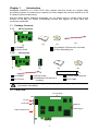
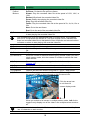
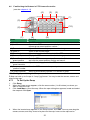
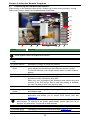
Chapter 1
Introduction
AVerMedia AVerDVR is a 32-bit PCI-E video capture card that works as a digital video
surveillance system. It enables you to capture true color images and real-time videos up to 32
IP camera inputs simultaneously.
With the latest Motion Detection technology, you no longer need to monitor every single
moment of the day; the system automatically records and triggers an alarm when any
movement is detected.
1.1 Package Contents
1.1.1
4/8/16 Channels
1.1.2
(3)
(2)
(1)
(1) NX8000
(2) Quick Guide
(4)
(3) Installation CD(manual is included)
(4) 30cm Watchdog line
32 Channels
(2)
(4)
(3)
FC - 26P
8
(1)
(5)
(1) NX8000
(2) I/O card
(3) Quick Guide
(4) Installation CD(manual is
inculded)
(6)
(5) 30cm Watchdog line
(6) I/O cable
If there is any damage, shortage or inappropriate item in the package, contact your
local dealer immediately.
1.2 Card Parts
I/O connector
TV OUT
Audio OUT
Reset pin
Watchdog pin
Relay & Sensor Port
1
Chapter 2
Hardware Installation
2.1 Minimum System Requirements
First, must verify if the computer meets the minimum system requirements.
CPU
Pentium® 4 2.8GHz or above recommended
Motherboard
Intel 875, 915, 925, 945, 955, NVIDIA nFORCE4 SLi - Intel
Edition chipset
OS
Windows2000 Professional or Windows XP Professional
Expansion Slots
PCI-Ex1 Slot
RAM
DDR 512MB or above
Hard disk
120GB of free hard disk space, or at least 60GB free space for
each partition
Media
CD-ROM drive
VGA
16-bit high color SVGA graphic card with DirectDraw & YUV
rendering capability, 64MB video memory
Audio
i
Sound card and speakers
®
For AVerMedia Security Product Hardware Recommendation list update,
go to :
http://www.avermedia.com/AVerDiGi/Product/Detail.aspx?Id=83&Tab=System
Requirement.
2.2 Installing NX8004/NX8008/NX8016 Card
1.
2.
3.
4.
Remove the PC case cover.
Remove 1 bracket that covers the PCI slots. Save the screws.
Press the cards into the PCI-Ex1 slots firmly.
Secure the card with the screws.
NX8000 Card
2
2.3 Installing NX8032 and I/O card
1.
2.
3.
4.
5.
Remove the PC case cover.
Remove 2 brackets that cover the PCI slots. Save the screws.
Connect the NX8032 card and I/O card with the connection cable.
Press the cards into the PCI-Ex1 slots firmly.
Secure the card with the screws.
NX8032 Card
I/Ocard
2.4
Connecting the Watchdog line
Connecting the NX8000 to the motherboard reset switch panel, enables the unit to restart
automatically and reset the system when an error has been detected.
1.
2.
3.
Look for the labeled RESET SW switch lead and connect it to the NX8000 card reset pin.
Connect the supplied Watchdog line to the NX8000 card watchdog pin and the other end
to the motherboard RESET SW panel. If you are not sure, please refer to the
motherboard user manual.
You may now replace back the PC cover and connect all the cables.
Reset SW lead
Watchdog line
NX8000
3
2.5
Connecting the a TV, Audio device, Sensor and Relay device
1.
Connect one end of the RCA video cable (not supplied) to the TV OUT port and the other
end to the TV video input port. If you are not sure, please refer to the TV user manual.
Connect the audio devices to the Audio input port.
Connect the sensor and relay device to the sensor/relay interface.
2.
3.
Television
(Video OUT )
NX8000
RCA cable
TV OUT
AUDIO OUT
Speaker
(Audio OUT)
i
Sensor 4
Sensor 1
Alarm 4
Alarm 1
To connect the cameras, please refer to Chapter 5.2.
4
2.6
Dual Monitors Setup
The DVR system Supports Single and Dual monitor displays. When using dual monitors, the
E-map and Playback function will be display on the second monitor.
The Video configuration is different for each different VGA chipsets. Please follow the steps
below to setup the dual monitors display.
2.6.1
Graphic card with ATi chipset
1. Enter the ATI Catalyst Control Center, user can click the short-cut or right click on the
screen.
2. There are two modes to select ─ Basic and Advanced.
3. If user selected Basic mode, press the Quick Settings tab. Then select the Select a
different desktop mode and click Go.
5
4. Select the Extended Desktop and then click Finish.
5. If user selected the Advanced mode, click the View button.
6. In Display Manager, right click on the second Display on the right side and select Extend
Main onto monitor.
7. Adjust each monitor resolution to 1024x768.
6
2.6.2
Graphic card with NVIDIA chipset
1. Click the NVIDIA nView, and select the Dualview mode.
2. Adjust each monitor resolution to 1024x768.
3. To review if the display mode is correct, you can check the task bar. The task bar will show
on the first monitor only.
Monitor 1
Monitor 2
7
2.7 Sensor and Relay pinhole allocation on NX8000
The signal from the sensor (i.e., infrared sensors, smoke detectors, proximity sensors, door
sensors, etc.) is being transmitted to the I/O card, and this triggers the system to respond and
send signal to relay device (i.e., alarm, telephone etc).
1 2 3 4 5 6 7 8 9 10 11 12 13 14 15 16 17 18 19 20
Pin #
2.7.1
Definition
Pin #
Definition
1
Sensor input signal 1+
11
Relay Normal Close 1
2
Sensor output signal 1-(GND)
12
Relay Common 2
3
Sensor input signal 2+
13
Relay Normal Open 2
4
Sensor output signal 2-(GND)
14
Relay Normal Close 2
5
Sensor input signal 3+
15
Relay Common 3
6
Sensor output signal 3-(GND)
16
Relay Normal Open 3
7
Sensor input signal 4+
17
Relay Normal Close 3
8
Sensor output signal 4-(GND)
18
Relay Common 4
9
Relay Common 1
19
Relay Normal Open 4
10
Relay Normal Open 1
20
Relay Normal Close 4
Connecting the Sensor/Relay device to I/O card
The I/O Audio card enables you to connect (4) sensor inputs and (4) relay outputs. Just
connect the external sensor and relay pin directly to the pinhole on the NX8000 card. Check
the table below and locate which pinhole is assigned to sensor input and relay output.
1 2 3 4 5 6 7 8 9 10 11 12 13 14 15 16 17 18 19 20
2.7.2 I/O Card Sensor and Relay pinhole allocation:
The signal from the sensor (i.e., infrared sensors, smoke detectors, proximity sensors, door
sensors, etc.) is being transmitted to the I/O card and this triggers the system to respond and
send signal to relay device (i.e., alarm, telephone etc).
Pin #
Definition
Pin #
Definition
1
Sensor input signal 1+
11
Relay Normal Close 1
2
Sensor output signal 1-(GND)
12
Relay Common 2
3
Sensor input signal 2+
13
Relay Normal Open 2
4
Sensor output signal 2-(GND)
14
Relay Normal Close 2
5
Sensor input signal 3+
15
Relay Common 3
6
Sensor output signal 3-(GND)
16
Relay Normal Open 3
7
Sensor input signal 4+
17
Relay Normal Close 3
8
Sensor output signal 4-(GND)
18
Relay Common 4
9
Relay Common 1
19
Relay Normal Open 4
10
Relay Normal Open 1
20
Relay Normal Close 4
8
2.8
The Sensor input and Relay output Specifications
You may use the sensor input and relay output specifications table below for your reference.
A. Sensor Input Specification
(Ta=25°C)
Absolute Maximum Ratings
Parameter
Input
Symbol
Rating
Unit
Forward Current
IF
50
mA
Reverse Voltage
VR
6
V
Power Dissipation
P
70
mW
(Ta=25°C)
Electrical/Optical Characteristics
Transfer Characteristics
Output
Input
Parameter
Symbol
Min
Typ.
Max.
Unit
Forward Current
VF
-
1.2
1.4
V
IF=20mA
Reverse Voltage
IR
-
-
10
A
VR=4V
Terminal Capacitance
Ct
-
30
250
pF
V=o, f=1KHz
Parameter
Symbol
Min
Typ.
Max.
Unit
Collector Dark Current
ICEO
-
-
100
nA
VCE=20V
Collector-Emitter
Breakdown Voltage
BVCEO
35
-
-
V
IC=0.1mA
Emitter-Collector
Breakdown Voltage
BVECO
6
-
-
V
IE=10
*Current Transfer Ratio
CTR
50
-
600
%
IC
2.5
-
30
mA
0.2
V
IF=20mA, IC=1mA
pF
V=0, f=1MHz
Collector Current
Collector-Emitter
Breakdown Voltage
VCE(sat)
Isolation Resistance
RISO
Floating Capacitance
Cf
-
0.6
Cut-off Frequency
fc
-
80
Response Time (Rise)
tr
-
4
18
s
Response Time (Fall)
tf
-
3
18
s
*CTR=
IC
IF
-
0.1
10
11
5 x 10
10
Conditions
Conditions
A
IF=5mA, VCE=5V RBE=
-
DC500V, 40-60% R.H.
1.0
VCE=5V, IC=2mA
RL=100, -3dB
KHz
VCE=2V, IC=2mA
RL=100
100%
B. Relay Output Specification
Surge strength
Nominal power
:1500 VAC
Operating power
: 110mw ~ 200mw
: 200mw ~ 360mw
C. COIL RATINGS (at 20 oC )
Coil Nominal Voltage
(VDC)
5
Coil Resistance
10%
125
Pick-up Voltage Drop-Out Voltage
(VDC)
(VDC)
3.75
0.5
Nominal Current
(mA)
40
o
* Max Continuous Voltage at 20 C : 110% of Coil Nominal Voltage
D. CONTACT RATINGS
2.9
Contact Arrangement
1 Form C (SPDT)
max. Switch Power
max. Switch voltage
max. Switch current
125VA
60W
125VAC
30VDC
1A
Contact Resistance
≤ 100mΩ
Resistive Load
1A/125VAC
1A/30VDC
Connecting POS (Point of Sales)
®
AVerMedia AVerDVR can be integrated with POS system equipment. Connecting the POS
®
equipment to AVerMedia AVerDVR system thru RS232 connection, enables you to view,
record and keep track of the items that were sold. You may also select the camera on where to
display all the data. To connect, locate the RS232 port of the POS equipment and PC. Use an
RS232 cable (not supplied) to make the connection.
9
RS232 cable
i
For detail of POS installation, please refer to POS Quick Guide.
10
Chapter 3
Software Installation
This chapter describes how to install the DVR software.
The CD-Key is permitted for use on a single computer. It is prohibited to use the
CD-key on more than one computer. Once detected, this would cause a system
conflict and some of the features might fail to work on both PC.
Before installing the software, make sure that the Windows OS patches and the
video graphic card driver are UPDATED.
If you have an old version of the DVR software installed in your PC, the old copy
must be removed. To remove, click Start>Settings>Control Panel and then
double click Add/Remove Programs. In Add/Remove Programs list, select NV
DVR and then click Remove.
We HIGHLY RECOMMEND having three (3) separate drives for the main system
(OS and DVR software), storage and backup. The ideal hard disk size for the main
drive is 20GB. As for the storage and backup, at least 60GB each. The hard drives
format must be in NTFS. This way we can maintain an optimized system for your
security.
For Windows 2000, make sure the hyper-threading setting is DISABLED from the
PC BIOS system.
i
To ensure getting the latest copy of DVR software, go and download the updated
version from the following site:
Worldwide :
http://www.avermedia.com/cgi-bin/support_download.asp
US/CANADA:
http://www.aver.com (click on Support)
3.1
Installing DVR Software in Windows XP/2000
Upon turning the computer on, the system automatically detects the newly
installed hardware. When the Found New Hardware dialog box appears,
IGNORE it.
Remember : It is important to install the DVR software first, before installing the
drivers.
1. Place the installation CD into the CD-ROM
drive then click Install Surveillance
System. And follow the on-screen
instructions.
11
2. For Windows XP:
When the Install Driver notice appears, this
informs you that you are about to install the
divers. This may take a while depending on
the number of drivers needed to be
installed. Click “Continue Anyway” when
the Microsoft digital signature appears.
When prompt to restart the computer, select
Yes, I want to restart my computer now
then click Finish.
For Windows 2000:
When prompt to restart the computer, select
Yes, I want to restart my computer now
then click Finish. This time you have
already installed the DVR software.
After rebooting, the system again detects
the newly installed hardware. When the
Microsoft digital signature appears, Click
OK to complete the installation.
3. You may now run the DVR program. To run the application, click
desktop or click Start>Programs>DSS>NV DVR.
12
on your PC
Chapter 4
4.1
Using the DVR Software
Running the DVR Software
To run the application, double-click
>DSS>NV DVR.
on your PC desktop or click Start>Programs
For security purpose, some of the features would require you to enter User ID and Password
before it can be accessed. When the Authorization dialog box appears, key in your User ID
and Password. (If this is the first time, enter the one you have registered when installing the
software.)
4.2
Using the Virtual Keyboard
If the keyboard is not available, you may use the Virtual Keyboard. Just click
virtual keyboard. For uppercase and lowercase, click shift button.
13
to show the
4.3
Familiarizing the Buttons in Preview/Advanced Mode
(18)
(17)
(16)
(15)
(14)
(13)
(12)
(19)
(11)
(10)
(1)
Name
(1) Exit
(2)
(3)
(4)
(5)
(6)
(7)
(8)
(9)
Function
Call up the Logout dialog box.
In the logout dialog box, you may do the following:
-
Click Exit to close the DVR program.
Click Login to sign-in in different account.
Click Minimize to reduce the DVR to taskbar button.
Click Compact to switch to compact mode (see Chapter 4.4).
Click Guest to switch to the guest mode. In guest mode, the
functions are limited to preview and playback function only. For
complete functions of DVR, please login as an administrator.
- Click Cancel to exit Logout dialog box.
- Click About to update patch or find about the software info.
(2) Volume
(3) Split Screen
Mode
i
Adjust the sound volume.
Select from 7 different split screen types to view all the camera, or one
camera over the other or alongside on a single screen. It also allows
you to switch and view different camera number.
- If there are only 4 cameras, you won’t be able to switch to 9, 16, 13, and 32 split
screen mode.
- The DVR system will save the current operating mode (split screen mode, auto
scan, full screen, and compact mode status) when shutdown DVR application
and apply the mode for next login.
- When you are in single screen mode, Right click and Drag a square on the
area you want to enlarge.
- When you are in multiple-screen mode, Right click the video screen of the
camera and Drag on where you want to relocate it. To only display one of the
video in the multiple-screen mode, Left click on the video screen you only want
to display.
(4) Record
Start/stop video recording.
14
Name
(5) Emap
(6) Network
(7) Setup
(8) PTZ
(9) Preview
(10) Playback
(11) Status Bar
(12) Camera ID
(13) Snapshot
(14) Event log
(15) AutoScan
(16) Full screen
Function
Display the map in each area, and the location of camera/ sensor/ relay
and the warning. (see also Chapter 4.7)
Enable/disable remote system access. This feature allows you to
access DVR server from a remote location via internet connection. (see
also Chapter 8)
Configure the system settings. (see also Chapter 5)
Access PTZ control panel. Beside PTZ camera, DVR system also
support mega pixel IP camera. (see also Chapter 4.6).
Switch to Preview/Advanced mode. This allows you to view live camera
display.
Switch to Playback mode. This allows you to view the recorded video
file. (see Chapter 4.5)
Display the current date, time and hard disk free space.
Show the number of cameras that are being viewed. When you are in
single screen mode, click the camera ID number to switch and view
other camera.
Capture and save the screen shot either in *.jpg or *.bmp format.
Show the record of activities that take place in the system. (also see
Chapter 4.3.1)
Start/Stop video screen cycle switch. (see also Chapter5.1 #6)
Use the entire area of the screen to only display the video. To return,
press the right button of the mouse or ESC on the keyboard or click the
arrow icon.
Click the
arrow icon to
exit from full
screen display
mode
When you switch to full screen in multiple-screen mode, Left click to
toggle to only display one of the video in the multiple-screen mode or
all.
(17) Alarm
Button
(18) Alarm
(19) On Screen
Keyboard
Click to trigger defined alarm(see also Chapter 5.9 Alarm Button)
Alert and display warning info. Only Administrator-level can reset and
turn on, off and trigger the Sensor and Relay by right-clicking the item in
the Sensor and Relay list.
If the keyboard is not available, you may use the Virtual Keyboard.
15
4.3.1
Using Event Log Viewer
Show the record of activities that take place in the system.
1. Click the Event Log button on DVR system main interface. The Event log viewer window
will show up.
2. Select the Date to view or search certain event log by key word. Enter the key word in
Find Text column and click Search button.
3. To filter the records, select and click the select button to display Event, System, Operation,
Network or All.
4. The events list which display on the screen can be saved as text file format. To save the
events list, click Save button.
5. To view POS event log, click POS Viewer bar to call out the POS event log window.
(6)
(1)
(2)
(3)
(4)
(5)
Name
(1) POSDB Path
(2) Before/After
Function
to change the
The storage path for POS event log. Click
storage path.
Set a time period before and after of POS event log.
16
Name
(3) Channel
(4) Search String
(5) Full Reception
Function
Select the POS event log of channel
Enter specific key word or word string to search the POS event log.
Mark the “Match whole word exactly” box if wants to find exactly key
word or word string of POS event log.
Display the POS event log detail that user selected from Search
to save the POS event log. Click
Result window. Click
to
print out the POS event log.
(6) Search Result
Display the POS event log of search result. Click
to print out the search result.
search result. Click
4.4
to save the
Familiarizing the Buttons in Compact Mode
To view in Compact mode, click Exit button. In the logout dialog box, click Compact.
(1)
Name
(1) Split Screen
Mode
i
(2)
(3)
(4)
(5)
Function
Select from 7 different split screen type to view all the camera, or one
camera over the other or alongside on a single screen.
- If there are only 4 cameras, you won’t be able to switch to 9, 16, and 13 split
screen mode.
- When you are in single screen mode, Right click and Drag a square on the
area you want to enlarge.
- When you are in multiple-screen mode, Right click the video screen of the
camera and Drag on where you want to locate it. To only display one of the
video in the multiple-screen mode, Left click the video screen you want to
display.
(2) AutoScan
Start/Stop video screen cycle switch
17
Name
(3) Alarm
(4) Playback
(5) Advanced
4.5
Function
Alert and display warning info.
Switch to Playback mode. This allows you to view the recorded video
file. (see Chapter 4.5)
Switch to Preview/Advanced mode.
Familiarizing the Buttons in Playback Mode
To switch in Playback mode, click Playback button at the lower right corner of
Advanced/Preview mode user interface.
Name
(1) Split Screen
Mode
i
Function
Select from 6 different split screen type to playback the recorded
video file of all the camera, or one camera over the other or alongside
on a single screen.
To view 32 channels, click 16 split screen button to switch channel
display.
- If there are only 4 cameras, you won’t be able to switch to 9, 16, and 13 split
screen mode.
- To zoom in an area on the screen, Right click and Drag a square on the area
you want to enlarge.
(2) Progress bar
(3) Hour Buttons
i
Show the progress of the file being played. You may move the bar to
seek at any location of the track.
Select and click to playback the recorded video file on the specific
time frame.
The Hour buttons represent the time in 24-hour clock. The blue bar on top of the
hour button indicates that there is a recorded video file on that period of time.
While the red bar indicates that you are currently viewing the recorded video file.
18
Name
(4) Playback
Control
Buttons
End: Go to the end of the recorded video file.
Select the date on the calendar and the time from 00 to 23 to where
to start playing the recorded video file.
(5) Date
i
Function
Begin: Move at the beginning of the recorded video file.
Previous: Go back to the previous frame.
Slower: Play the recorded video file at the speed of 1/2X, 1/4X, or
1/8X.
Rewind: Wind back the recorded video file.
Pause: Briefly stop playing the recorded video file.
Play: Play the recorded video file.
Faster: Play the recorded video file at the speed of 2x, 4x, 8x, 16x or
32x.
Next: Go to the next frame.
The numbers from 00 to 23 represent the time in 24-hour clock. The numbers
from 01 to 16 represent the camera ID. The blue colored column indicates that
there is a recorded video file on that period of time. While the red colored column
indicates on where to start playing the recorded video file.
(6) Preview
(7) Playback
(8) Status bar
(9) Camera ID
(10) Output
(11) Segment
(12) Print
(13) Snapshot
(14) Full screen
Switch to Preview/Advanced mode.
Switch to Playback mode. This allows you to view the recorded video
file.
Display the recorded date, time and play speed.
Show the number of cameras that are being viewed. When you are in
single screen mode, click the camera ID number to switch and view
other camera.
Save the segmented file in *.mpg, *.avi, or *.dvr format (see also
Chapter 4.8).
Keep a portion of the recorded video (see also Chapter 4.8).
Print the screen shot.
Capture and save the screen shot either in *.jpg or *.bmp format.
View in Playback-compact mode. To return, press the right button of
the mouse or ESC on the keyboard or click the arrow icon.
Click the arrow icon
to exit from full
screen display mode
When you switch to full screen in multiple-screen mode, Left click to
toggle to only display one of the video in the multiple-screen mode or
all.
i
When there are dual monitors with 32 channels, the full screen mode will split
into 16 channels on each monitor.
19
Name
(15) Event log
(16) Bookmark
(17) Visual
Search
(18) Find Next
(19) Event
Search
(20) Intelligent
Search
Function
Show the record of activities that take place in the system. To filter the
records, select and click the option button to only display Event,
System, Operation, Network or POS.
Mark a reference point when previewing the recorded video file to
which you may return for later reference. You may also set it to
protect the file. (See also Chapter 4.9)
Search from a specific camera by Date, Hour, Minute, 10 Seconds
and Second. (See also Chapter 4.10)
Search for the next event or changes in the motion detector frame.
You can use this when you are using Intelligent Search or Event
Search function.
Search from the recorded activities that take place in the system (i.e.,
Sensor, Motion, Video Loss, POS) . (See also Chapter 4.11)
Search the changes in the motion detector frame (See also Chapter
4.12).
20
4.6
Familiarizing the Buttons in PTZ Camera Controller
(see also chapter 4.13)
(4)
(3)
(2)
(1)
(5)
(10)
(6)
(7)
Name
(1) Close
(2) AutoPan
(3) Focus +/(4) Zoom +/(5) Direction buttons
(6) Camera ID pane
(7) Save Camera
preset position
(8) Camera lens
speed controller
(9) Camera preset
position number
(10) Group AutoPan
4.7
(8)
(9)
Function
Exit PTZ camera controller.
Operate the PTZ cameras automatically based on the selected
camera group preset position number.
Adjust the focus manually to produce clear image.
Zoom in and out the image.
Adjust and position the focal point of the PTZ camera.
Display the PTZ camera number that is being operated.
Save the PTZ camera preset position number. Select the camera
and click the preset position number and save it.
Adjust the moving speed of the PTZ camera lens.
Move the PTZ camera to the preset point.
Select to automatically operate PTZ camera in group.
Setting Up and Using the Emap
E-Map can hold up to 8 maps in *.bmp/*.jpg format. You may locate the camera, sensor and
relay on the map.
4.7.1
1.
2.
3.
4.
To Set Up the Emap
Click Emap.
When the Emap screen appears, click the area number (1 to 8 buttons) on where you
want to insert the map.
Click Load Map to insert the map. When the open dialog box appears, locate and select
the map and click Open.
When the inserted map appears on the Emap screen, click Edit. You may now drag the
camera, sensor, and relay icons to its place on the map. Icons on the map can be
21
relocated anywhere. Right click camera icon can select the camera direction in 8 angles.
If you are going to locate the icon on the map to other area, you need to drag the icon to
the black pane at the bottom of the Emap screen and then switch to the area on where
you want to locate the icon.
To bring all the icons back to the black pane at the bottom of the Emap screen, click
Reset Icon.
5.
When you are done, click Edit button to save the new setting. To close Emap screen,
click Exit.
4.7.2 To Use the Emap
To use the Emap:
1.
2.
Click E-map.
In the Emap screen, click the camera icon to switch on the area where the camera is
located on the map and to display the video at the upper right corner of the Emap screen.
At the lower right corner of the Emap screen, it lists all the warning message.
3.
Click Exit to close Emap screen.
22
4.8
To Cut and Save the Wanted Portion of the Recorded Video
1.
Use the Playback Control buttons or drag the bar on the playback progress bar and
pause on where you want to start the cut. Then, click Segment to set the begin mark.
2.
Use the Playback Control buttons or drag the bar on the playback progress bar and
pause on where you want to end the cut. Then, click Segment to set the end mark. To
cancel segmentation or set the segment marks from the start, click Segment button
again.
3.
4.
Click Output button to save the wanted clip.
In the Save As dialog box, locate on where you want to save the file, type the filename,
and select the video format.
4.9
1.
2.
To Bookmark a Section of the Video
Click Bookmark. The video playback stops when the bookmark button is executed.
In the Bookmark dialog box, you may do the following:
Add to include the new reference mark in the bookmark list. You may select to
enable/disable file protection.
Edit to change the mark description or enable/disable file protection.
Delete to remove the selected reference mark in the list.
Delete All to remove all the reference marks in the list.
Exit to close Bookmark dialog box.
i
3.
When the bookmark is protected, the file won’t be overwritten.
The protected bookmark file will be deleted when the Delete the recorded
data is enable in the System setting.(also refer to 5.1 System setting)
Select and click one in the bookmark list to preview the file.
4.10 To Search Using the Visual Search
1.
2.
Click Visual Search.
In the Visual Search Setting dialog box, select the Camera number and the date. Then
click OK.
3.
When a series of frames appear by date, click on the frame to display another series of
frames and search by every Hour of that date, every 3Minutes of that hour, every 10
Seconds of that minute, every Second of that 10 seconds. To go back, click
. To
.
view from the selected frame and close event search, click
23
4.11 To Search Using the Event Search
1.
2.
3.
4.
5.
Click on the video screen on where you want to search.
Click Event Search. The Event Search text (red) would appear at the lower left corner of
the screen.
In the Event Search Setting dialog box, check the type of condition you want to search. If
you select POS, in the Find Text box, type the word. Then, click OK to start searching.
The video search would stop at the frame that matches the condition. To keep on
searching click
.
You may also set to search and list all the result. Just check the Output Event List box.
In the Search Duration section, set the Begin Time, End Time and Searching Interval.
Then, click OK to start searching.
When the Event list appear, click and select the item you want to view.
4.12 To Search Using the Intelligent Search
1. Click on the video screen on where you want to search.
2. Click Intelligent Search. The Intelligent Search text (red) would appear at the lower left
corner of the screen.
3. When the Intelligent Search Setting dialog box and motion detector frame appear, you
may adjust the sensitivity bar and the motion detector frame size and location. To set
motion detector frame size and location, left click and drag on the screen. Then, click OK
to start searching. The video search would stop at the frame that matches the condition.
To keep on searching click
.
You may also set to search and list all the result. Just check the List box. In the Search
24
Duration section, set the Begin Time, End Time and Searching Interval. Then, click OK
to start searching.
4.13 To Setup the IP PTZ Camera
1. In the PTZ control panel, click Setup.
2. Select the camera number and check the Use PTZ box.
3. In the Connection Settings section, select the Protocol where the PTZ camera is
connected and IP Camera Site that IP or URL of IP camera. Then, click Save to keep the
settings.
4. Use the IP PTZ control panel and adjust the position of the IP PTZ camera.
5. In the Preset Setting section, select the preset number to assign a number for the IP PTZ
camera current position. Set the DwellTime (1-60 sec) for how long the IP PTZ camera
stays in that position before it moves to the next one. If you want to add description, check
the Show Preset Name box and in the Preset Name text box, type the word. When done,
click Save to keep the settings.
6. Repeat step 4 & 5, if you want to save another PTZ camera position.
7. Restore AutoPan Time: set a time period for restoring auto path function after the IP PTZ
camera has been moved. Mark the check box and set the time period in second.
8. When is done, click OK to save the setting or Click Cancel, to leave without saving the
new setting
9. The on screen PTZ controller is enabled when the IP PTZ camera is connecting to NX
DVR system. User will see a small PTZ controller icon display on the right corner of
25
channel screen.
10. Click on screen PTZ controller icon to call out the control l panel.
i
-
User can move the on screen PTZ controller to any position of screen
The on screen PTZ controller only will display on one channel screen at a time.
26
(4)
(5)
(1)
Name
(1) Adjust arrow
(2) Speed up/down
(3) Focus +/(4) Zoom +/(5) On screen PTZ
controller icon
(2) (3)
Function
To move the camera lens to up, down, left or right
To speed up or down movement of camera lens
Adjust the focus manually to produce clear image.
Zoom in and out the image.
To call out or close the on screen PTZ controller
27
Chapter 5
Customizing the DVR System
In the Preview/Advanced screen mode, click
button to customize your DVR. When the
DVR configuration setup selection appears, select and click the buttons you want to change
the setting.
5.1
System Setting
In the System Setting dialog box, click OK to accept the new settings, click Cancel to exit
without saving, and click Default to revert back to original factory setting.
(10)
(1)
(2)
(3)
(11)
(4)
(12)
(5)
(13)
(6)
(14)
(7)
(8)
(9)
(1) Storage Path
Set the directory on where to save the data. When there is not enough free space to record
one hour data, the system automatically replaces the oldest data. In case you have more than
one storage path, the system automatically saves the data to the next storage path. You may
also add additional network-attached storage (NAS) for extremely high storage capacity.
Select the Enable network storage check box to send the recorded video in network-attached
storage. To add network storage, the Internet storage drive/folder must be mapped as Network
Driver in DVR server. Enable network storage first, and then, click Add. In Browse For Folder
windows, select drive C and right click mouse button, select Map Network Drive option.
28
In the Map Network Drive windows, select the Drive and fill in the network drive direction in
Folder column if you know. Or click Browse to find the folder direction. Click Finish to
complete the network drive mapping. After the network drive has been added, user needs to
create a folder for network storage. In Browse For Folder windows, select the network drive
and right click mouse button to add a new folder. And then, click OK. User should see a new
storage folder display in Storage path list.
By default the data is stored in C:\Data, to insert another storage path, click Add. To remove
the selected path, click Delete. If you want the system to automatically erase the data after a
certain days, enable the Delete recorded data after check box and enter the numbers of days
in Days text box. If you want the system to automatically erase the event and alarm log after a
certain days, enable the Delete event and alarm log after check box and enter the numbers
of days in Days text box. To change logs save direction, enable Move to and select the new
save direction
(2) Hard Disk Calculator
Estimate the hard disk recording capacity. The result of calculation is a rough value which only
for reference. The hard disk record capacity will be varied by the real record quality and
complexity of video scene.
Click
, the hard disk calculator windows will show up. Total Recording time is the current
hard disk recording capacity. Enter the expect hard disk size or expect recording time in
Expected HD Size or Expected Record time, and then click Calculate button. Click OK to
exit the hard disk calculator windows. The hard disk calculation will base on the recording
setup and current hard disk setup.
29
(3)Language
Customize the system to display the tool tips and dialogs based on the selected language. By
default the language is in English.
(5) Attention Please
Check the attentiveness of the person who is monitoring the system. You may set the number
of times the Attention dialog box to appear in a day in Times per day text box. To check the
graph on how fast the person response, click Analysis.
When this feature is enabled, the Attention dialog box would appear. The person who is
monitoring the system must enter the same number that appears from the left box at the right
text box and then click OK.
(6) TV Out
Select the camera you want to appear on TV and set the time gap from 3 to 10 sec. before it
switches to the next camera.
- Advance button
Select the video card channel and camera that user wants to display on TV. Click Advance to
enter configure interface.
~ Autoscan
(1) The channel group display
(2) When the audio of IP camera is enabling, the channel of audio will be list in Audio
drop down list
(2) Select the display mode as Autoscan.
(3) Preview screen: Live camera video would be displayed here.
(4) Video Mode: Select the video mode user wants to display on screen. The system
will auto cycle switch to display the next channels.
30
(1)
(2)
(3)
(4)
(5)
~ Fixed Layout
(1) The channel group display
(2) When the audio of IP camera is enabling, the channel of audio will be list in Audio
drop down list
(3) Select the display mode as FixedLayout.
(3) Preview screen: the selected camera video will preview in here.
(4) Video Mode: Select the split mode of TV out display.
(5) Cameras: User can select the cameras that user wants to display on the screen.
Only those selected channels would be displayed on the screen. Also,
the camera will be displayed by the selecting order.
(1)
(2)
(3)
(4)
(5)
(6)
(7) Configuration
Backup a copy of all the settings and allows you to regain the same settings back. To save the
current settings, click Export. To replace the settings with the one you have saved, click
Import.
(8) System Controller Setup
To configure the parameters that is for communicating with the System Controller (an optional
accessory). Also please refer to user manual of the System Controller.
31
Enable – Mark the check box to enable the System Controller function.
Model – Select model of the System Controller.
Port – Select the com port that is connected with the System Controller. Click Setup to
configure com port value. The com port value is shown in below table:
Baud rate
9600
Data bits
8
Parity
No
Stop bit
1
Flow control
No
ID – Set an ID for DVR server (0~99). This ID is a key for communicating between the
System Controller and the DVR server.
i
When the DVR server ID is X, the DVR server can be controlled by System Controller
irrespective of the DVR ID that is selected in System Controller.
(9) System Configuration
To configure the DVR system date, time and IP address.
Date/Time Setup
1. Select the Time Zone of DVR server located
2. Select the Month and Date. Click arrow button can switch to different month.
3. Adjust the Time by click spin box arrow button.
4. Click OK to save the configuration.
IP Setup
32
Obtain an IP automatically (DHCP): To use DHCP server assigning DVR server a IP
address.
Using the following IP address: Assign a fixed IP address for DVR server
IP ADDRESS: Assign a constant IP address which a real IP addresses give from
ISP to DVR system.
Do Not assign the DVR to 1.0.0.0 network segment. It will ca use the DVR can not
access to Internet due to the un-recognize to 1.0.0.0 IP segment.
i
Mask: It is a bitmask used to identify the sub network and how many bits provide
room for host addresses. Enter the subnet mask of the IP address which user has
assigned to DVR system.
GATEWAY: A network device act as a passageway to internet. Enter the network
gateway IP address
- DNS: Domain Name Server translates domain names (such as www.abb.com.tw) to
IP addresses. Enter the IP address of DNS if it is available.
(10) Login
Enable the conditions in Login section you want the system to automatically carry out.
- Auto Login when OS start
Execute the NV DVR when the operating system is started.
- Ask for password when login
Request to enter User ID and Password each time the NV DVR is executed.
- Auto record when login
Automatically start video recording when the NV DVR is executed.
- Login to compact mode
Switch to compact mode directly when the NV DVR is executed.
- Silent Launch
Enable the DVR system minimizes on the system tray automatically right after start up.
- Guest Mode
Automatically log in Guest mode when the NV DVR is executed. In guest mode, the
functions are limited to preview and playback only.
- Default user
Automatically log in to the selected default user when the NV DVR is executed.
(11) Miscellaneous
Enable the conditions in Miscellaneous section you want the system to perform.
-
33
-
-
Status Report
Send a daily system event and attention analysis report. To change the e-mail settings,
click Setup.
Desktop Lock
Deactivate the [Ctrl-Alt-Del] and [Windows] keyboard key functions.
Beep if no signal
Make sound when the video signal is lost.
Shutdown OS when exit
Turn off the PC when the NV DVR application is being closed.
Mandatory Record
Always record video when software is running
Enable Overlay
To enhance video signal for better video quality.
i
Only support on NV6000 (Exp) and NV7000H card.
Auto Scan Period
Set the time gap of the Auto Scan function from 3 to 10 seconds. This automatically
switches to the next video in cycle depending on the set time gap.
- Temperature Display
Select the format of temperature -- °C or °F
- Playback Mode
Select the mode of playback the video.
Select date and time: Select the date and time which user wants to playback.
Play the last file: Automatically playback the video from the last hour
Instant Playback: Automatically playback the video which has just recorded
- Date Format
Select the date format which wants to display in Select date and time playback mode
(12) POS
Set from which camera screen to display the data from the POS equipment. Click Setting, to
set the POS Console Setting. To set the text flow and color format, click Advanced. (see also
Chapter 5.1.1)
(13) Dual Monitor
Enable/disable dual monitor display. Click Setting to
select the dual monitor display mode.
-
34
(14) UPS (Uninterruptible Power Supply)
Protect the system from damaging, such as power surges or brownouts. This automatically
gives time to close the DVR properly when the battery backup power has reached the
Shutdown when capacity below percentage level setting.
The UPS device must be connected to your computer (refer to your UPS user’s guide)
The UPS application must meet Windows 2000 or Windows XP system
requirements.
i
5.1.1
To Set the POS Setting:
1. In the System Setting dialog box, POS section, click Setting. To set the text flow and color
format, click Advance.
2. In the POS Console Setting dialog box, click Add to set a new POS setting, Modify to
change the POS setting, and Delete to remove the selected POS setting. Click OK to
save and close POS Console Setting.
3. In the POS Mapping dialog box, click OK to accept the settings and Cancel to exit without
saving the new setting.
(1)
(2)
(3)
(6)
(4)
(5)
(7)
(8)
(1) POS Name
(2) Protocol
(3) Skip first
(4) Start Testing
: Enter a name to identify the POS.
: To select the protocol, click Setting button (see Setup POS
Protocol)
: Set the number of lines you want to be removed
: Click to test POS setting. You will see a test result on the right
side of POS Mapping window.
35
Test result
display
(5) Setup…
: Set the COM Properties. If you are not sure, please contact
your POS service provider.
(6) Port Setting
: Select the Local or Remote port to where it is connected.
Local - select the COM port number which is connected.
Remote – Use the UDP protocol for remote connection if POS
system can broadcast to Internet. Enter the IP
address of the remote station.
: Select to which camera number to display the transaction text.
: Enter the word you want to be removed.
(7) Map to Channel
(8) Text Filter
36
Setup POS Device
There are 4 default POS devices. If user uses the POS device beside defaults, user can add
new POS device and rules. The POS device can be added up to 50 include defaults.
Setup Standard POS Device
•
1.
2.
3.
4.
5.
6.
•
Add New POS Device
Click Add
Enter the POS device name in Name column
Select the Type as Standard
Click OK to save
To modify existing device, double click it.
Click Default can be reset back to original setting.
Add Rules
1. Select the POS device form device list
2. Click Add in Rules section
3. In Rule Setting windows, select Group. Each group has a limited number of times ; please
refer to the “Maximum” and “Remainder” information in Rule Setting windows. The Line
End, Page End, and Bill End group only can be set once.
- Line End: set a rule to separate each line.
- Page End: set a rule to switch page.
- Skip Cmd: set a rule to discard a string or character.
- Include: set a rule for a lime with a string or character to be displayed.
- Exclude: set a rule for a line with a string or character to be concealed.
- Bill End: set a rule to divide each transaction.
4. Select Type – Ascii or XML
5. Enter the string or character as the rule in Data column. The maximum length is 31
characters.
37
6. Click OK
7. Click Save. The configuration will be lost without saving.
8. To modify existing replace rules, double click it.
•
Character Replacement
Set a rule to replace a character or word in POS data. The maximum replacement is 8.
1. Select a POS device from device list
2. Click Add in Replace section
3. Old Data: select the Type(Ascii or Hex) and enter word or character that wants to be
replaced
4. New Data: select the Type (Ascii or Hex) and enter the word or character that will replace
it in Old Data.
5. Click OK
6. Click Save. The configuration will be lost without saving.
7. To modify existing replace rules, double click it.
•
Adjust Rule Priority
User can set the priority of rule groups. Select the group and click up/down arrow button to
move the priority level. The upper position, the priority is higher.
38
Setup XML POS Device
XML can only work with the POS data is transmitting in XML format.
9
Device: select or add a new device. Only device that supports XML can be configured in
here. Click Add to add a device. Enter device name and select Type as XML. The POS
device can be added up to 50 include defaults.
Page Start: Beginning of data for transaction
Page End: End of data for transaction
Tag: select a root tag and sub tag as a range for data transaction to DVR server. Click Add to
set a tag. Click Save. The configuration will be lost without saving.
39
Please refer to the following example for more detail.
<TicketStart> → Page Start
<Header> → Root tag
<MessageVersion>1.0</MessageVersion>
<Date>20060317</Date>
<Time>164216</Time>
<RegisterID>3</RegisterID>
<Shift>4</Shift>
<CashierID>000000009</CashierID>
<JrnlTransNum>3</JrnlTransNum>
<JrnlID>0</JrnlID>
</Header>
</TicketStart>
<Item>
<SaleTotals>
<Item>
<SaleTotals>
<Item>
<SaleTotals>
<TenderEvent>
<TicketComplete> → Page End
40
→ Sub tag
5.2
Camera Setting
In the Camera Setting dialog box, click OK to accept the new settings, click Cancel to exit
without saving, and click Default to revert back to original factory setting.
(1)
(2)
(3)
(6)
(4)
(7)
(5)
(1) Camera Icons
Select the camera number you want to adjust the video setting. To select all the cameras,
enable the ALL check box. To select more than one camera, Right click on the camera icon.
To select one camera only, Left click on the camera icon. The camera icon turns red when it
is selected.
(2) Enable
Set to enable/disable the selected camera. When there is no video source on the camera, we
suggest disabling it so that the system won’t detect it as video loss error.
(3) Camera
- Display
Enable/disable to show the video. Even if the video of the selected camera is hidden
-
you can still record the video and preview it in playback mode.
Name
-
Change the camera name.
Description
Add a short comment.
(4) IP Camera Information
Click the camera icon to display the connected IP camera information in here.
(5) Object Counting
Select the two regions on the screen and the system will count the objects that appear from
one selected region to another selected region. (See also 5.2.1).
(6) Video Screen
Display the video of the selected camera.
(7) IP Camera Setup
The video source is coming from Network camera.
IP Setting: click IP Setting to enter the IP Camera Settings windows. In the IP Camera
Settings dialog box, select to connect using Protocol or URL and then enter the
required info. User also can click Search Device to find the selected protocol of
41
camera on the LAN network. If user is not sure the camera is which model, click
Detect Model to find the correct model of camera. If it requires user identification,
enable Authentication check box and enter User ID and Password. To enable audio,
click Enable Audio check box. If you are not sure of the Protocol or URL info, please
refer to the IP camera manual or contact your IP camera local distributor.
In Camera Setting interface, click Detail to configure Video, Senor, Relay, and Direct
Link by IE of the IP camera.
- Video Setting
Select the video size and adjust the Frame Rate, Quality, Bright, Contrast, Hue, and
Saturation of the selected camera.
- Recording Setting
~ Save Original Format: Save the video that is compressed by IP camera’s
compress mode.
9 Only decode key frame for Preview: When selected the Save Original
Format selection, user can mark Only decode key frame for Preview this
option. When previewing video, DVR system only shows key frame and
one frame per second.
~ Transcode by MPEG4 Encoder: Decoding the video and compress video
again by using MPEG4 encoder.
42
- Direct Link by IE
Using IE browser to connect to camera and view the real time video. Click Direct
Link by IE,the IE browser will pop up and connect to camera. The video viewing
interface will be varied by different brand of camera.
- I/O Control
~ Sensor Setting
To setup sensor that is embedded on the
1.
2.
3.
4.
5.
~
camera.
Click the drop-down list and select the
sensor ID number.
Enter sensor name in Name column
The system automatically detects the
camera and input relates information. In
the Content section, enter sensor
description.
In the test section, click Test to check
the sensor status. Red is high and
Green is low.
Click OK to exit and accept the setting
and Cancel to exit without saving the
setting.
Relay Setting
To setup relay device that is embedded on
1.
2.
3.
4.
5.
the camera.
Click the drop-down list and select the
relay ID number.
Enter relay name in Name column
The DVR system automatically detects
the camera and input relates
information. In the Content section,
enter relay description.
In the test section, click Test to trigger
relay. Red is high and Green is low.
Click OK to exit and accept the setting
and Cancel to exit without saving the
setting.
43
5.2.1
Setup the Object Counting
1.
Click Detail to enter the object counting setup window.
2.
Enable Detected Regions in Display section. This enables the object counting
information show on the screen. Moving Object will enable the object size frame to show
on the screen.
Click Region1 and press left button of mouse and drag the area that user wants the
object to be counted. And then, click Region2 and drag another area that user wants the
object to be counted, too. Those selected regions will mark in different color. The system
will count the objects that move between the selected regions.
Click Object size to define the detected object dimensions. Press left button of mouse
and drag on the screen. To see the object size frame on screen, enable Moving Object
in Display section.
Adjust the sensitive of object detecting.
To test the setting, mark the Directions (In/Out) want to be test and click Start. The
testing result will show in Test section.
Click OK to save the setting. Click Cancel to leave the setup window without saving.
The object counting information will be display on the screen of upper part.
3.
4.
5.
6.
7.
8.
Object counting information display
Region 1
Region 2
Object size frame
44
5.3
Recording Setting
In the Recording dialog box, click OK to accept the new settings, click Cancel to exit without
saving, and click Default to revert back to original factory setting.
i
The gray selections are not support for IP camera.
(1)
(5)
(2)
(3)
(6)
(7)
(4)
(8)
(1) Camera Icons
Select the camera number you want to set the recording setting. To select all the cameras,
enable the ALL check box. To select more than one camera, Right click on the camera icon.
To select one camera only, Left click on the camera icon. The camera icon turns red when it
is selected.
(2) Recording Mode
The blocks from 00 to 23 represent the time in 24-hour clock. To record in full 24 hours, select
the recording mode and click the ~ button. If you want to only record at a particular time, click
the colored block beside the recording mode then click on the time blocks. When the system
starts recording a red triangle mark would appear at the upper left corner of the screen. The
recording modes are listed below:
- Always Recording
Record the video from the selected camera and save it to the designated storage path
(see also Chapter 5.1 #1).
- Motion Recording
Start recording the video from the selected camera only when the system detects
movement. Once a motion is detected, the system automatically saves the previous
frames and stop based on the Start Record Prior and Stop Record After settings.
- Smart Recording
Automatically switch to recorded at the maximum frame rate setting once a motion is
detected and if there is no motion, it records at the minimum frame rate setting. Set the
maximum frame rate setting in (5) Frame Rate.
- No Recording
The system won’t do any recording.
(3) Motion Detection
Adjust the sensitivity of the motion detector. The higher the value, the finer the sensitivity is
45
detected. When it detects a motion, a green triangle mark would appear at the upper left
corner of the screen.
(4) Frame Rate
Set the maximum number of frames to be recorded during motion and motionless state. The
frame rate ranges from 1 to 30 for NTSC and 1 to 25 for PAL. The higher the frame rate, it
uses more hard disk space.
i
Only available when user selected “Transcode by MPEG4 Encoder”
in Video Setting at Camera setting section(see Chapter 3.2 #9)
(5) Video Screen
Display the video of the selected camera
(6) Mask/Shield Edit
Mask, mark an area on the screen to disregards the motion in the marked area and to only
monitor outside the marked area. As for the Shield, it covers an area on the screen and the
covered area would not be visible on the screen and recorded. (see also Chapter 5.3.1 and
5.3.2)
(7) Information Prompt
Move the mouse to “i” icon for information prompting.
(8) Compression Type
Select from 3 compression types. User can refer the table
below to check the NX card supports what type of
compression. H264 is the latest and advanced video
compression format that delivers better video quality and
smaller file size but this uses more CPU resource. Advanced
MPEG4 and MJPEG, both provide a standard for color picture
compression rate. MPEG4 uses higher compression rate and
smaller file size. While MJPEG uses slightly lower
compression rate and bigger file size.
Using the Advanced MPEG4 enables you to encrypt the
recorded video that way only the person who knows the
password can clearly view the video playback. The file size
46
would become 10 to 30% more. Enabling the Video Encryption check box, you will be
prompted to enter the password and retype the password for confirmation. Make sure not to
forget the password for you would not be able to decrypt the video without it.
The
symbol would appear on the upper right corner of the encrypted video screen. You
may see the video during live recording (see also Chapter 5.3.3).
i
Only available when user selected “Transcode by MPEG4 Encoder”
in Video Setting at Camera setting section(see Chapter 3.2 #9)
5.3.1 To Mask/Shield an area on the screen:
1.
2.
3.
In the Mask/Shield Edit section, activate the Enable Mask/Enable Shield check box.
In the Edit section, select between Mask or Shield and click the ~ button.
Click and drag a frame on the (7) Video Screen to create Mask or Shield area.
i
Only available when user selected “Transcode by MPEG4 Encoder” in Video
Setting at Camera setting section(see Chapter 3.2 #9)
5.3.2 To show and change the color of the Mask:
1.
2.
Enable the Show Mask check box.
In the Color section, select the color and click ~button.
5.3.3 To Playback Encrypted Video:
On Playback, Webcam, and Remote Console video screen, just click
password to decrypt and playback the video.
To encrypt the recoded video back, click
i
and enter the correct
and enter a WRONG password.
It is important to encrypt the video again, to avoid unauthorized user viewing the
video.
47
5.4
Network Setting
In the Network Setting dialog box, click OK to accept the new settings, click Cancel to exit
without saving, and click Default to revert back to original factory setting. For the network
service ports that use by DVR server, please see Appendix C.
(1)
(7)
(2)
(8)
(3)
(9)
(4)
(5)
(10)
(6)
(1) Server Name
Assign a name for the DVR unit. Alphabet letters and numbers only.
(2) Transmitting Cameras
Select and click on the camera number in the Transmitting Camera section you want to make
it accessible via internet using WebViewer, Remote Console, PDA Viewer and Hand Viewer
(still image). To select all the cameras, enable the ALL check box.
(3) Main Configuration
Set the Server IP and Remote Console Port number. The system will automatically detect your
Server IP address. You need this when accessing DVR server from the remote location via
internet.
(4) Dynamic DNS (Domain Name System)
Enter the Domain Name and Password. To use this feature, go to http://ddns.avers. com.tw
and register.(also see Appendix A) You will be prompted to enter CD key number, product
name, password, and user information. Use this service if the IP address changes each time
when you connect to internet.
(5) Remote Control Server
Enable/disable remote control from remote application (ex. CM3000). Enter the remote
accessing port in Port column. The default value is 5555.
i
User also can manually run this function. To run, click Start > Programs > DSS >
remote control server icon appears on the
Tool > Remote Control Server. The
taskbar when the remote control server is enabled. (also see Chapter 12)
(6) Network Video Configuration
Set up the video quality and frame rate for viewing and transmitting to the remote program.
Scrolling adjust bar to set the Quality level and FrameRate level.
(7) WebViewer Configuration
Activate Enable Anonymous Login to remotely access the DVR server without the need of
password
48
(8) Voice Phone
The Talk to Web-Client is to use the 2-Way Talk feature that allows the client and server to
talk via internet using microphone. Make sure both microphone and speakers work before
using this feature. If the Talk to Web-Client is disabled, the person in the DVR server side can
only hear the voice from the client side that is when the WebCam 2-Way Talk button is
activated. (see also Chapter 8.1 #6).
i
Make sure that your Webcam Digital Signature is updated yearly; else you won’t be
able to access the DVR server from the DVR WebViewer. To update/download your
WebViewer Digital Signature, click Update WebViewer Digital Signature. Make
sure your PC is connected to internet.
(9) Network Time Synchronization
Adjust the DVR system time same as network time server. Fill in the Time Server IP address
or domain name. Select Automatic Synchronize time to set automatic synchronize time on a
daily basis. Or, user can click Synchronize Time Right Now to adjust time right away.
(10) Other Configuration
- UPnP
Enable UPnP function to automatically
configure the port setting on the local
network. This function is available when
there is UPNP device in the same network.
It will write the DVR port information into
the router or other network device (see
Appendix B)
- Enable White List
An access permit list for the remote
accessing of DVR server. Enter the IP
address and click Add. Or, enter a range
of IP address and click Add. To delete the
IP from the list, select the IP and click
Delete button. To reset the input, click
Clear button.
- Enable HandyViewer
Enable remote users to use a PDA or a mobile phone to access DVR server and select the
video size and quality. (See also Chapter 8.5 and 8.6)
-
Network Bandwidth Limit
By Channel: Set the network bandwidth by each channel.
All: Set the total network bandwidth consumption limit.
49
5.5
Schedule Setting
Schedule to record, backup, enable network, reboot and disable alarm of all the cameras
either weekly or one time. The number from 00 to 23 represent the time in 24-hour clock. The
left most column display the days in a week.
To Set the Schedule Setting:
and
buttons to shift the calendar to the left
1. Select the date in the calendar. Use
or right.
2. Select the condition you want to schedule in the drop down list.
- Record
Activate all the cameras to start video recording at the set time based on the
Recording setting (see also Chapter 5.3).
- Backup
Save another copy of all the data at the set time and specified backup path. DVR
automatically updates and only backup the data that are not yet included in the
.
archive. To assign backup path, click
i
-
-
i
Make sure the backup folder and storage folder are not on the same drive.
Enable Network
Activate DVR remote system to access at the set time. After the appointed time, the
Network function will be disabled. If the Network function is already enabled, the
Network function will not be disabled when the appointed time has ended.
Reboot
Restart the PC at the appointed time.
Make sure the Windows operating system is set NOT to require you to login user
name and password. This way the system will be able to run DVR program.
-
Disable Alarm
Deactivate the alarm at the set time temporarily.
- Turn on Relay #
Active the Relay at the set time. If there are no Relays are connected, Turn on Relay #
function will not display in drag down list. The Relay number will depend on how many
Relays are connected.
3. Specify to either schedule it weekly or one time. Click ~ to make a selection.
4. Click on the blocks to set the schedule (see also Chapter 5.5.1). Or click All to select all.
To store the setting, click Save. To remove the settings, click Clear.
50
5. To end Schedule Setting, click OK to exit and accept the setting and Cancel to exit without
saving the setting.
5.5.1 To set schedule at a specific portion of time in that hour:
1.
2.
3.
Right click the colored blocks.
In the Select time dialog box, click to enable or disable the portion you want to set.
Click OK to accept the setting and Cancel to exit without saving the setting.
51
5.6
Backup Setting
In the Backup Setting dialog box, the number from 00 to 23 represent the time in 24-hour clock.
The numbers from 01 to 16 represent the camera number. When you back up the file, you
may find QLog Viewer and Player application included in the backup folder (see also Chapter
6).
To Backup file:
and
1. Select the date of the recorded file in the calendar you want to backup. Use
buttons to shift the calendar to the left or right.
2. In the table below, click on the blue block to select the recorded file or click camera
(01~16) or time (00~23) to select the whole row or column. The blue block turns red
when it is selected. The block that appears in white doesn’t have data. If you want to set
the specific time, right-click on the selected block. Then, set the time to start and end.
3. Check the information beside the calendar.
Selected Files : Show the number of files selected.
Require Space : Show the total size of the selected file.
4. Enable Auto partition and select to divide the file size into DVD-R or CD-R. DVR
automatically backup and divide the file sizes to facilitate burning into DVD or CD disc.
5. Enable Start backup when CD/DVD or USB storage device is detected that the Backup
setting windows will display on screen automatically when the DVR system detects
CD/DVD-ROM disk or USB storage device. Right after user select the period of backup file,
click
, the DVR system will start backup without confirmation.
6. Enable Include player when backup that will included a Qplayer program for playback
backup file in backup folder when backup. Only administrator user has the authority to
enable or disable this function.
7. If you do NOT want to keep the recorded file in the storage folder, enable Delete files
after Backup check box.
8. Click
9. Click
to set the path on where to store the backup file.
to start archiving the selected file.
52
10. In the Processing… dialog box, to stop archiving press Abort. When done, in the Backup
Path list, shows the archived item. To burn the file in CD, you need to have NERO 6 or
above installed in your PC then select the item in the list and click Burn. Click Exit to end
this procedure and burn it later.
11. In CD/DVD Backup, enable/disable Delete file after burning check box to remove the
archived file after burning. Click Burn to start and Exit to cancel this process.
5.7
Sensor Setting
The I/O device must be installed to use this function.
The DVR system also support external I/O box and user
can install external sensors. For external sensor setting,
please referring to the sensor vendor user’s manual.
To Set the Sensor Setting:
1. Click the drop-down list and select the sensor ID
number.
2. Enter sensor name.
3. Click External IO to configure external I/O device if
it is available(see also 5.7.1)
4. The system automatically detects the sensor and
input relates information. In the Content section,
enter sensor description.
5. In the test section, click Test to check the sensor
status. Red is high and Green is low.
6. Click OK to exit and accept the setting and Cancel
to exit without saving the setting.
53
5.7.1 To Setup External I/O Box
The DVR system can connect the external I/O box for more installed of I/O devices.
1.
2.
3.
4.
5.
6.
7.
8.
Click Add.
Mark Enable box to enable this external I/O box.
Select the Brand of external I/O box from drag down list.
In Port Setting, different brand of external I/O box may have different port parameters.
Please refer to the external I/O box’s user manual for port setting information. Using the
default value if user uses AverMedia External I/O box.
Click OK to save the setting.
To add more than one external I/O box, click Add and follow the above step 2~4.
In External I/O box setup dialog, user will see all added External I/O. Click added
External I/O box and click Add to scan the connected relays and sensors.
In Add Module windows, click Scan to scan the connected relays and sensors on the
External I/O box.
54
9.
All connected relays and sensors will be listed. User can click radio button to control
relays’ status. And then, click OK to save the setting and click Cancel to exit and without
saving.
10. All connected External I/O box and their modules will be listed as tree topology in
External I/O Setup windows.
55
11. To view the all I/O devices information, click I/O Map.
5.8
Relay Setting
The I/O device must be installed to use this function.
To set the Relay Setting:
1.
2.
3.
4.
Click the drop-down list and select the relay ID number.
Enter sensor name.
Click External IO to configure external I/O device if it is available(see also 5.7.1)
The system automatically detects the card and input number. In the Content section, enter
sensor description.
5. In the test section, click Test to check the relay status. Red is high and Green is low.
6. Click OK to exit and accept the setting and Cancel to exit without saving the setting.
56
5.9
Alarm Setting
In the Alarm Setting dialog box, click Add to insert and set new alarm setting, click Delete to
remove the selected alarm setting, click OK to exit and save the setting, Cancel to exit without
saving, and Default to revert back to original factory setting.
(1)
(2)
(3)
(7)
(4)
(5)
(6)
To set the Alarm Setting:
1. Click Add to insert and set a new alarm setting. Click the items in the (7) Alarm Setting
List, if you want to modify the alarm setting.
2. In (1) Alarm Setting number/Name/Description, display the selected alarm setting
number in the list below. Enter alarm name and description.
3. In (2) Enable Time, the number from 00 to 23 represent the time in 24-hour clock. Select
the time and click the block you want to activate or deactivate the alarm function. When it
is deactivated the color of the block turns white.
4. In (3) Conditions, you can set “Trigger if any” to activate if it falls to one of the conditions
or “Trigger if all” to activate if it falls to all conditions.
In Camera section, select and click on the camera number (01 to 16) in Motion
Detected and Video Loss to set the condition for the system to alarm.
In Missing and Suspicious Object Detected, click the camera number (01 to
16)and select the certain object on the screen (right click on camera number for
detailed setting)), and when the certain object is missing or doubtful, the system will
alarm.(see also Chapter 5.9.12) In Scene Change, when the camera has been
moved, the system will alarm, too.
In Audio Detect, click the camera number (01 to 16) to the system to alarm when
detect the abnormal audio.
5. In (4) Sensor, select and click on the sensor number (use W and X to select the sensor)
to set the condition for the system to alarm. If the sensor normal status is high, set the
sensor condition to low (see chapter 5.7 step #4).
Click IP Camera Sensor to configure IP camera’s sensor condition. To set the sensor
57
condition for the system to alarm, click High or Low column. The column with a circle
means is selected.
-
Enable/disable the Abnormal Event check box, to set the condition of the event for
system to alarm.
• Reboot: when the DVR system reboot without abnormal condition, the system
will send out the alarm message.
• Abnormal Reboot: when the DVR system reboot in irregular condition, the
system will send out the alarm message.
• Recording is switched off: when the recording has been stopped, the system
will send out the alarm message.
• Network is switched off: when the network connection of DVR system is lost,
the system will send out the alarm message.
• Hard Disk failed: when the hard disk can’t work normally, the system will send
out the alarm message.
• Temperature: set a temperature limited of system for system to alarm. When
DVR system temperature is over the temperature limited, the system will send
out the alarm. The system supports °C and °F temperature mode.
• Illegal Entry: any objects move between selected regions which user has set up
in Object Counting section (see Chapter 5.2.1), the system will send out the
alarm. Select the entry (object moves from region 1 to 2 or from region 2 to 1)
and camera for system alarm detection.
i
-
Only the camera has been setup in Object Counting will be available
for selecting in Illegal Entry.
Enable/disable the POS Keyword check box, to scan the data from the POS if it
matches the keyword (see also Chapter 5.9.10).
58
-
-
Enable/disable the Alarm Message check box, to active with external alarm
message by your own program. For the detail configuration, please contact the local
reseller.
Enable/disable the Alarm Button check box, to active manual alarm function (see
also Chapter 4.3#(17)). To define alarm message of manually alarm trigger. Click
alarm button and select the alarm button # and fill in the description of alarm button.
Once the Alarm button has been activated and defined, the Alarm button will display
on Advanced UI.
-
Continue trigger duration: Set a time period that when sensor has been trigger
and stay in the same status for that period, then the alarm will be sent out.
6. In (5) Alarm Reset, click the camera number (use W and X to select the alarm) to set the
reset condition of alarm. Once alarm is reset, all alarm action will stop at the moment. If
the sensor normal status is high, set the sensor condition to low.
Click IP Cam Sensor to IP camera sensor reset condition. Click High or Low column to
set the reset condition of alarm.
7. In (6) Action, you may now set the alarm action for the system to perform when the alarm
condition is activated.
- Launch E-Map
Display mini Emap screen.
- TV Out
Switch to only display the video on TV from where the alarm is activated or selected
camera.
- Enlarge Camera View
Switch to only display video in Preview/Advanced mode from where the alarm is
activated.
- Relay Output
Set to enable/disable the relay operation when the alarm is activated and to extend
59
-
-
-
-
-
-
-
-
-
additional time in second before it stops the relay operation (see also Chapter 5.9.1).
IP Camera Relay
Set to enable/disable IP camera relay trigger. Click ON column to enable/disable the
relay trigger. The blank column means the trigger is off.
Play Warning Sound
Play alarm sound. To setup click Detail (see also Chapter 5.9.2).
Make Phone Calls
Dial and contact the number in the list. To setup click Detail (see also Chapter 5.9.3).
To use this feature, the PC must have a voice modem connected to it. The supported
audio system is only 8KHz and 16Bit mono.
Send E-mail
Send an electronic text message. To setup click Detail (see also Chapter 5.9.4).
File Transmission via FTP
Upload file to remote computer thru FTP (File Transfer Protocol). To setup click Detail
(see also Chapter 5.9.5).
Start Recording
Record the video from the selected camera. To setup click Detail (see also Chapter
5.9.6).
SMS (Short Message Service)/MMS (Multimedia Messaging System)
SMS transmits only text messages to mobile phone. MMS transmits text messages
and images over wireless networks using the wireless application protocol (WAP).
Make sure your mobile phone support this feature and your PC is connected to
GSM/GPRS modem. To setup click Detail (see also Chapter 5.9.7).
PTZ preset point
Position the PTZ camera based on the preset point setting. To setup click Detail (see
also Chapter 5.9.8).
Alarm SOP (Standard Operation Procedure)
List the instructions to inform the person of what to do when the alarm is activated. To
setup click Detail (see also Chapter 5.9.9).
Send to CMS (Central Management System)
Enable/disable the selected camera to send video to CMS when the alarm is activated
(see also Chapter 5.9.10)
Launch Program
To call up the external program that is provided by 3rd party. Click Detail and click
to locate the program path. Enable Multiple instance check box to allow the program
can be executed multiple times at the same time.
60
-
Snapshot
Take a snapshot when the alarm is activated.
a. Select Camera: specify which channel video to be snapshot when the alarm is
occurred.
Alarm Camera: when a channel has an alarm occurred, and then, the DVR
system will snapshot the channel video.
Camera # (1~32): the selected channel would be snapshot when an alarm is
occurred.
b. Video Size: select the size of snapshot picture.
c. Number of picture: the number of picture that is going to be taken.
d. Snapshot Interval: a time gap for next snapshot
e. Save Path: a storage path for saving snapshot pictures.
f. Delete image after: set a certain amount of snapshot image storage limit. When
the snapshot image is over the limit, and then, the system will start recycle the
snapshot image.
5.9.1 To Setup Alarm Relay:
1. Beside the Relay Output check box, click Detail.
2. In the Alarm Relay dialog box, select from the available relay list and in the ON column,
set to enable/disable the relay operation when the alarm is activated.
In the Retrieve time check box, you may enable/disable to extend the relay operation time
and set the duration in second.
3. Click OK to exit and accept the setting and Cancel to exit without saving the setting.
61
5.9.2 To Setup the Alarm Sound Setting:
1. Beside the Play Warning Sound check box,
click Detail.
2. In the Alarm Sound Setting dialog box, click
to select other wav file from other source
or folder, Play to listen, Record to make a
new copy of a sound.
3. If you click Record, you will be prompted if
you want to replace the file.
Click OK to
continue and Cancel to discontinue.
4. When the Sound Recorder appears, use the
record control panel to record, stop, play,
rewind and forward. If you want to keep the
existing file, click File > Save As…, enter
filename and click Save. Make sure you have
microphone connected to your PC.
5. Click OK to exit and accept the setting and Cancel to exit without saving the setting.
5.9.3 To Setup Call Out List:
1. Beside the Make Phone Calls check box,
click Detail.
2. In the Call Out List, click Add to insert a new
contact number, Modify to edit the selected
item, Remove to delete the selected item,
Test to check if it is working.
3. In the Call Out Setting, enter the phone
to select
number and description. Click
existing sound recorded messager and
Record to make a new voice message.
4. When the Sound Recorder appears, use the
record control panel to record, stop, play,
rewind and forward. If you want to
the existing file, click File > Save As…, enter filename and click Save. Make sure you
have microphone connected to your PC.
The supported audio system is only 8KHz and 16Bit mono.
5. Click OK to exit and accept the setting and Cancel to exit without saving the setting.
62
5.9.4 To Setup Send E-mail Setting:
Beside the Send Email check box, click Detail. In the E-mail Setting dialog box, click OK to
exit and save the setting and Cancel to exit without saving the setting.
(1)
(2)
(3)
(4)
(1) Mail Server
Enter the SMTP Server and port. If your e-mail system requires user identification, enable
Authentication check box and enter User ID and Password.
(2) Mail
To check if it is working, click Test Account button.
From:
Enter the sender e-mail address.
To and CC: Enter the recipient email address and separate it with comma or a semicolon
(;).
Subject:
Enter the message title.
Message:
Type the message.
(3) Email Notice Setting
Notice Interval: Set the period of time before it sends another e-mail notice.
Embedded image : Select the image size and set the number of frames.
Attach image when sensor is triggered: When the sensor is triggered, the system will
capture the image and send the image to the certain e-mail address with the alarm
message.
(4) Modem Dial up Setting
If you are using dial up modem, enable Auto Dial up check box and select the modem
name. You may also set the time to disconnect automatically, just enable the Auto
Disconnect after check box and set time.
5.9.5 To Setup FTP Setting:
1.
Beside the File Transmission via FTP check box,
click Detail.
2.
In the FTP Setting dialog box, enter the FTP IP, port,
user ID and password.
3.
In Number of Pic text box, enter the number of
sequence images that want to send when file is
transmitting. The maximum number of picture can be
transmitted are 16.
4.
In Upload image when sensor is triggered, select the camera that the images will be
capture and send when the sensor is triggered.
63
5.
Click OK to exit and save the setting and Cancel to exit without saving the setting.
5.9.6 To Setup Alarm Recording Setting:
1.
Beside the Start Recording check box, click
Detail.
2.
In the Alarm Recording Setting dialog box,
select the camera to enable/disable video
recording. Enable All to select all cameras.
3.
In the Frame Rate selection, select As Setting
to record the number of frames based on the
Recording Setting or Max to record the
maximum of frames based on the available
speed (maximum is 32 pictures) .
4.
In the Stop Recording after text box, mark and set the number in second for the
program to continue recording after the alarm has ended. The time range is 1~600
seconds. If user doesn’t mark and set the time, the alarm recording will continue
recording until alarm is reset.
5.
Click OK to accept the new settings and Cancel to exit without saving.
5.9.7 To Setup SMS/MMS Setting:
To use this feature, GSM/GPRS modem is
required. Connect the GSM/GPRS modem to
the serial COMM port of PC. Beside the
SMS/MMS check box, click Detail.
1. Select the port number in ComPort drop
down list from where the GSM/GPRS
modem is connected.
2. Click Enter Pincode button to enter the
pin code of phone number if your phone
system required.
3. In Phone Num text box, enter the contact
number.
4. You may now set to send thru SMS &/or
MMS. If you enable SMS setting, just enter
the message in the text box.
5. If you enable MMS, enter the APN name,
WAP IP, MMS address and the message.
Enter the Login account and password if
required. If you are not sure, please
contact your mobile service provider. The Import… button allows user to import the presaved configuration and also export the current configuration by clicking Export… button.
6. Attach image when sensor is triggered: Select the camera that the images will be
capture and send when the sensor is triggered.
7. Click OK to accept the new settings and Cancel to exit without saving.
i
Make sure your ISP provider and cell phone provider both support JPG file format
transmitting.
64
5.9.8
To Setup PTZ Preset Point:
Beside the PTZ preset point check box, click Detail. In the Trigger PTZ Preset Setting dialog
box, select the PTZ camera number then select the Enable check box. Select the position of
the PTZ camera when the alarm is activated and ended. For the PTZ camera ended point,
user also can select one preset position or Auto Path between preset position group.
5.9.9
To Setup Alarm SOP:
Beside the Alarm SOP check box, click Detail. In the
step text boxes, type the standard protocol when the alarm is activated. When the alarm is
activated, the Standard Operation Procedure dialog box will appear. Just click Next to see the
next instruction, Back to see the previous instruction, Finish to end and Abort to terminate.
5.9.10
To Setup CMS Setting
Beside the Send to CMS check box, click Detail. In the CMS Setting, select the camera to
enable/disable sending the video to CMS. Enable All to select all cameras. Then, click OK to
accept the new settings and Cancel to exit without saving.
5.9.11
To Setup POS Keyword Setting
1. Beside the Send to POS Keyword check box, click Detail.
2. In the POS Keyword Setting, select the camera to enable/disable scanning the keyword.
Enable All to select all cameras.
3. Enter the text below keyword text box. Click Add to include the keyword in the list. To
remove, select the word in the list and click Delete. You may only add 8 keywords. User
can define the color for each keyword. To set the color, click the color panel after next to
POS keyword column and a color selection window will pop up. Select the color that user
wants and click OK.
65
4. Click OK to accept the new settings and Cancel to exit without saving.
Click to change
color of keyword
5.9.12 Missing, Suspicious Object, and Scene Change Detected
-
Missing Object
Select the certain object on the screen for the system to detect; when the object is
disappear or move and the system will alarm. Click OK to exit and save the configuration.
To exam the setup condition, click Start Test.
1.
Select the camera number (0-16) and press RIGHT button on the mouse to call up
the setup windows.
2.
Click Save to capture the image for comparing reference first. To view the captured
image, enable the Show Reference Image check box. The captured image will
display on screen. The reference image is sharing with the Suspicious Object and
Scene Change function.
3.
Mark the Enable check box to setup the condition.
4.
Use the mouse to click and drag the frame on the screen. User can drag more than
one frame.
5.
Sensitivity: Set the system detects sensitivity.
6.
Delay Time: Set the lasting time for system to detect the object.
7.
To reset all object frames, click Clean. To clean an object frame, click right button of
mouse and drag the object frame that user want to clean.
-
Suspicious Object
Suspicious Object is including the object missing or the doubtful object appears on the
screen. Click OK to save and exit the setup windows. To exam the setup condition, click
66
Start Test.
1.
Select the camera number (0-16) and press right button on the mouse to call up
the setup windows. And then, click the Suspicious Object Tab.
2.
Click Save to capture the image for comparing reference. To view the captured
image, enable the Show Reference Image check box. The captured image will
display on screen. The reference image is sharing with the Missing Object and
Scene Change function.
3.
Mark the Enable check box to setup the condition.
4.
Sensitive: Set the system detects sensitivity.
5.
Delay Time: Set the lasting time for system to detect the object.
6.
Use the mouse to click and drag the frame on the screen.
• Maximum_Object: the maximum detect size. The objects are out of the
maximum detect area will be disregard. Use mouse to click and drag the frame
on the screen.
• Minimum_Object: the minimum detect area. When the objects are smaller
than the minimum detect area, the system will disregard. Use mouse to click
and drag the frame on the screen.
7.
Enable Mask
Mark an area on the screen to disregards the motion in the marked area and to
only monitor outside the marked area. Mark the Enable Mask check box, click
and drag the mask frame on the screen.
8.
To reset all object frames, click Clean. To clean an object frame, click right button
of mouse and drag the object frame that user want to clean
-
Scene Change
When the camera has been moved, the system will alarm.
1.
Select the camera number (0-16) and press right button on the mouse to call up
the setup windows. And then, click the Scene Change Tab.
2.
Click Save to capture the image for comparing reference. To view the captured
image, enable the Show Reference Image check box. The captured image will
display on screen. The reference image is sharing with the Missing Object and
Suspicious Object function.
3.
Mark the Enable check box to setup the condition.
4.
Sensitive: Set the system detects sensitivity.
5.
Delay Time: Set the lasting time for system to detect the movement.
6.
Change Rate: Set the camera movement range which compare with the original
position.
7.
Enable Mask
Mark an area on the screen to disregards the motion in the marked area and to
only monitor outside the marked area. Mark the Enable Mask check box, click
and drag the mask frame on the screen.
8.
To reset all object frames, click Clean. To clean an object frame, click right button
of mouse and drag the object frame that user want to clean.
67
68
5.10 User Setting
Only administrator can access User Setting. The maximum user accounts are 256.
In the User Setting dialog box, click Add to insert a new user, Delete to remove the selected
user, Edit to modify the user control right, OK to exit and accept the setting, and Cancel to
exit without saving the setting.
After clicking Add or Edit, you may customize the user control setting. OK to exit and accept
the setting, and Cancel to exit without saving the setting
(1)
(2)
(3)
(4)
(5)
(6)
(7)
(8)
(9)
(1) Authorization level
Select the status of the user. Only Administrator-level can access User Setting, and reset the
Alarm status when using the Remote Console.
(2) Control Right
Enable the items that would allow the user to access.
(3) Web Viewer
Enable/disable Web Viewer control right that allow the user to operate from a remote location
using internet explorer.
- Remote Console
Allow the user to remote modify DVR system setting.
- Remote LogViewer
Allow the user to view the event log from remote site.
- Remote EMAP
Allow the user to view the E-map of DVR from remote site.
- IP Camera
Enable/disable user to add new IP camera when using the Web Viewer.
69
Remote Access Time
Enable Infinite check box to access DVR without time limit. If you want to set time limit,
enter the number of minutes in Minute text box.
(4) Visible Camera
Select the camera number that would allow the user to access or view. To select all the
cameras, enable the ALL check box.
(5) Time Span
Set the user account a specific time period that user only can use given account to login DVR
program in that specific period. Mark Enable check box and select the Activation Date and
Expiry Date.
(6) Name
Enter the user name.
(7) Description
Enter the user description.
(8) Password
Enter the user password.
(9) Confirm Password
Enter the same user password for confirmation.
-
70
Chapter 6
Backup Video Players
You can playback the backup files using QPlayer applications. When you back up the
recorded file, QPlayer applications are automatically included in the backup folder.
With QPlayer, it is the same as in Playback mode and supports six (6) different split screen
types to view all the video at the same time. User even can select the different language of
display UI. The only difference is that there are no Preview and Playback buttons.
To run the application, go to backup folder and double-click Q Player icon.
6.1
Familiarizing QPlayer Buttons
(15)
(14)
(13)
(12)
(11)
(10)
(9)
(8)
(16)
(7)
(17)
(1) (2)
Name
(1) Split Screen
Mode
i
(4)
(5) (6)
Function
Select from six (6) different split screen type to playback the
recorded video file of all the camera, or one camera over the other
or alongside on a single screen.
- If there are only 4 cameras, you won’t be able to switch to 9, 16, and 13 split
screen mode.
- To zoom in an area on the screen, Right click and Drag a square on the area
you want to enlarge.
(2) Progress bar
(3) Hour Buttons
i
(3)
Show the progress of the file being played. You may move the bar
to seek at any location of the track.
Select and click to playback the recorded video file on the specific
time frame.
The Hour buttons represent the time in 24-hour clock. The blue bar on top of the
hour button indicates that there is a recorded video file on that period of time.
While the red bar indicates that you are currently viewing the recorded video file.
(4) Playback Control
Buttons
Begin: Move at the beginning of the recorded video file.
Previous: Go back to the previous frame.
Slower: Play the recorded video file at the speed of 1/2X, 1/4X, or
1/8X.
Rewind: Wind back the recorded video file.
Pause: Briefly stop playing the recorded video file.
71
Name
(4) Playback Control
Buttons
End: Go to the end of the recorded video file.
Select the date on the calendar and the time from 00 to 23 to
where to start playing the recorded video file.
(5) Date
i
Function
Play: Play the recorded video file.
Faster: Play the recorded video file at the speed of 2x, 4x, 8x, 16x
or 32x.
Next: Go to the next frame.
The numbers from 00 to 23 represent the time in 24-hour clock. The numbers
from 01 to 16 represent the camera ID. The blue colored column indicates that
there is a recorded video file on that period of time. While the red colored column
indicates on where to start playing the recorded video file.
(6) Open
(7) Status bar
(8) Camera ID
(9) Export
(10) Segment
(11) Full screen
Access the backup video file.
Display the recorded date, time and play speed.
Show the number of cameras that are being viewed. When you are
in single screen mode, click the camera ID number to switch and
view other camera.
Export includes Snapshot, Print, Output Video Clip, and Backup
function.
Snapshot: Capture and save the screen shot either in *.jpg or
*.bmp format.
Print: Print the screen shot.
Output Video Clip: Save the segmented file in *.mpg, *.avi, or
*.dvr format (see also Chapter 4.8).
Keep a portion of the recorded video (see also Chapter 4.8).
View in Playback-compact mode. To return, press the right button
of the mouse or ESC on the keyboard or click the arrow icon.
Click the arrow
icon to escape
from full
screen display
mode
When you switch to full screen in multiple-screen mode, Left click
to toggle to only display one of the video in the multiple-screen
mode or all.
i
When there are dual monitors with 32 channels, the full screen mode will split into
16 channels on each monitor.
(12) Visual Search
Search from a specific camera by Date, Hour, Minute, 10 Seconds
and Second. (See also Chapter 4.10)
72
Name
(13) Find Next
(14) Event Search
(15) Intelligent
Search
(16) Language
(17) De-interlace
Function
Search for the next event or changes in the motion detector frame.
You can use this when you are using Intelligent Search or Event
Search function.
Search from the recorded activities that take place in the system
(i.e., Sensor, Motion, Video Loss, POS). (See also Chapter 4.11)
Search the changes in the motion detector frame (See also
Chapter 4.12).
Select the UI display language.
To enhance the video quality. Set the de-interlace mode to #1, if
you are capturing motionless picture and #2, if it captures lots of
movement.
73
Chapter 7
Using Functional Keys
The DVR system provides shortcut keys. The table shows the function keys and descriptions.
Function Keys
description
Q
Exit System
F1
Display system information
F2
Start recording
F3
Enable network function
F4
Access system settings
F5
Switch to playback mode
F6
Access E-map setting
F7
Access PTZ camera control panel
F8
Snapshot
F9
Switch to Full Screen
F11
Switch to AutoScan
CTRL + F
Freeze function
CTRL + B
Quick Backup
Ctrl + A
Turn on/off hardware AGC (Auto Gain Control)
74
Chapter 8
Using the Remote Programs
You can use Microsoft Internet Explorer to access DVR server by entering the IP address or
domain name. To use this feature, make sure that you are connected to the internet and the
Network feature is enabled.
Accessing this feature for the first time you will be prompted by your browser to install
WebCamX.cab, allow the installation and you should be able to connect and login afterwards.
For Windows 2000, click Yes when the Security Warning dialog box appears.
For Windows XP, click Install when the Internet Explorer - Security Warning dialog box
appears.
After installing the WebCamX.cab and when connecting to the DVR server, you are required to
enter User ID, password and select the network type.
i
If you are not in a LAN network environment, remote playback video may be unsmooth due to network speed limitation. Slow network transmission speed may
possibly cause system performance drop as well.
75
Chapter 8 Using the Remote Programs
8.1
Familiarizing the DVR WebViewer Buttons
Right-clicking on the webcam video screen, enables you to start video recording, change
video quality, switch camera and enable/disable DirectDraw.
(15)
(14)
(13)
(12)
(11)
(10)
(9)
(8)
(1)
Name
(1) DirectDraw
i
(2)
(3)
(4)
(5) (6)
(7)
Function
Enhance the video quality.
Not all graphic cards can support this function.
(2) Received file
size
(3) Camera frames
(4) Split display
mode
(5) Audio
(6) 2-Way Talk
(7) Record
(8) Event Log
Viewer
(9) Remote Console
i
Indicate the size of the data being sent per second.
Indicate the number of frames per second.
Select from six different split screen types to view all the cameras.
It also allows you to switch and view different camera number.
To view 32 channels, click 16 split screen button to switch channel
display.
Enable/disable remote sound.
Enable/disable 2-way audio function. This function allows the client
and server to talk via internet using MIC.
Make sure your microphone and speakers work before using this
function. If the DVR server Talk to web-client setting is disabled,
you won’t be able to hear from the other side.
Save the video of the selected camera in AVI format.
Display the Event logs, Operation logs, POS logs, System logs,
and Network logs.
Initiate Remote Console. The interface is the same as DVR
application and allows you to control DVR server (see also
Chapter 8.2).
If you are using Windows Vista, please make sure you execute IE as system
administrator. To execute IE as system administrator, please right click on IE
shortcut icon and select “To execute as Administrator”.
(10) Remote E-Map
(11) Remote setup
(12) Select a PTZ
Display the DVR server Emap screen (see also Chapter 4.7).
Change the DVR server settings (see also Chapter 8.1.1).
Initiate PTZ camera controller (see also Chapter 8.2)
76
Name
camera
(13) Snapshot
(14) Full screen
(15) Select cameras
to view
Function
Capture and save the screen shot in *.bmp format.
Use the entire area of the screen to only display the video.
To return, Right click the mouse or press ESC on the keyboard.
Select to the view camera from different server. In Select Camera
dialog box, Display column, click to enable/disable viewing the
camera. In Video Quality column, click to select between High,
Normal or Low.
- Click Add Server and select the server type between DVR and
IP Cam to add.
- Click Delete Server to delete the selected item.
- Click Import to replace it with the previous saved list.
- Click Export to save the list.
- Click Apply All to change all the camera video quality based on
the selected setting.
- Click OK to exit.
i
To add IP Cam, user need to enable IP Camera control
right at the User setting of DVR system.(see 5.10)
77
8.1.1 To Setup Remote System Setting
Click OK to exit and save the setting and Cancel to exit without saving the setting. The setting
here applies to Remote DVR only.
(1)
(2)
(3)
(4)
(5)
(7)
(8)
(6)
(1) Camera Name
Select the camera you want to adjust the settings.
(2) Enable
Set to enable/disable the selected camera. When there is no video source on the camera, we
suggest disabling it so that the system won’t detect it as video loss error.
(3) Camera Name
- Display
Enable/disable to show the video. Even if the video of the selected camera is hidden you
-
can still record the video and preview it in playback mode.
Name
-
Change the camera name.
Description
Add a short comment.
(4) Video Adjustment
Adjust the Brightness, Contrast, Hue and Saturation of the selected camera.
(5) Recording Setting
Select the size of the video and click the ~ button. The higher the size, the larger the file it
create. You can also activate the Enable Deinterlace to enhance the video quality. Set the
Enable Deinterlace mode to #1, if you are capturing motionless picture and #2, if it captures
lots of movement.
(6) Enable Audio
Select to assign the audio channel of the selected camera. You can only assign one audio
channel to one camera source. This way you can record both audio and video.
(7) Quality
Adjust the video quality. The higher the value, the lower the compression level and uses more
hard disk space.
(8) Frame Rate
Set the number of images per second of the video to be recorded. The frame rate ranges from
1 to 30 for NTSC and 1 to 25 for PAL. The higher frame rate, it uses more hard disk space.
78
8.2
Familiarizing the WebViewer PTZ Buttons
(1)
(2)
(5)
(6)
(3)
(4)
Name
(1) Direction buttons
(2) Select PTZ
(3) AutoPan Groups
(4) Camera preset
position number
(5) Zoom +/(6) Focus +/-
Function
Adjust and position the focal point of the PTZ camera. Click the
center to pan automatically.
Choose to enable/disable the PTZ camera. In the Select PTZ
dialog box, Select column, click to enable/disable viewing and
controlling the PTZ camera.
Click OK to exit and save the setting and Cancel to exit without
saving the setting.
Operate the PTZ cameras automatically based on the selected
camera group preset position number.
Move the PTZ camera to the preset point. The camera position
number is setup in DVR site( see 4.13.1#5)
Zoom in and out the image.
Adjust the focus manually to produce clear image.
79
8.3
Familiarizing the Remote Console Buttons
(17)
(16)
(15)
(14)
(13)
(12)
(1)
(11)
(2)(3)
Name
(1) DirectDraw
i
(5)
(6)
(7)
(8)
(9)
(10)
Not all graphic cards can support this function.
(2) Exit
(3) Volume
(4) Split Screen
Mode
i
(4)
Function
Enhance the video quality.
Close the Remote Console.
Enable/disable the sound.
Select from six (6) different split screen type to playback the
recorded video file of all the camera, or one camera over the other or
alongside on a single screen.
To view 32 channels, click 16 split screen button to switch channel
display.
If there are only 4 cameras, you won’t be able to switch to 9, 16, and 13 split
screen mode.
To change the video quality, right-click on the screen and select between High,
Normal or Low.
(5) Record
(6) Emap
(7) Network
(8) Setup
(9) PTZ
(10) Preview
(11) Playback
(12) Status Bar
Start/stop video recording.
Display the map in each area, the camera/sensor/relay location and
the warning event. (see also Chapter 4.7)
Enable/disable remote system access. This feature allows you to
access DVR server from a remote location via internet connection.
Configure the Remote Console setting. (see also Chapter 8.3.1)
Access PTZ control panel. Beside PTZ camera, NV DVR system
also support mega pixel IP camera.(see Chapter 8.4)
Switch to Preview/Advanced mode. This allows you to view live
camera display.
Switch to Playback mode. This allows you to view the recorded video
file. (see Chapter 8.4)
Display the IP address and received file size.
80
Name
(13) Camera ID
(14) Event log
(15) Snapshot
(16) Full screen
(17) Alarm
8.3.1
Function
Show the number of cameras that are being viewed. When you are
in single screen mode, click the camera ID number to switch and
view other camera.
Show the record of activities that take place in the system. To filter
the records, select and click the option button to only display Event,
System, Operation, Network or POS.
Capture and save the screen shot either in *.jpg or *.bmp format.
Use the entire area of the screen to only display the video.
To return, Right click the mouse or press ESC on the keyboard.
Alert and display warning info. Only Administrator-level can reset and
turn on, off and trigger the Sensor and Relay by right-clicking the
item in the Sensor and Relay list.
To Setup Remote Console Setting
Click OK to exit and save the setting and Cancel to exit without saving the setting.
(1)
(2)
(3)
(4)
(1) Storage Path
Set the directory on where to save the data. When there is not enough free space to record
one hour data, the system automatically replaces the oldest data. In case you have more than
one storage path, the system automatically saves the data to the next storage path.
By default the data is stored in C:\RemoteData, to insert another storage path, click Add. To
remove the selected path, click Delete.
If you want the system to automatically erase the data after a certain days, enable the Delete
recorded data after check box and enter the numbers of days in Days text box.
(2) Language
Customize the system to display the tool tips and dialogs based on the selected language. By
default the language is in English.
(3) Remote Server
Enter the DVR Server IP and Port number.
(4) Channel Settings
The numbers from 01 to 16 represent the camera ID.
In Transmitting Channels section, enable the camera
number to receive the camera signal from the server.
In Visible Channels section, enable the camera
number to view the camera signal on Remote Console
screen. To select all the cameras, enable the ALL
check box.
81
8.4
Familiarizing the Buttons in PTZ Camera Controller
(5)
(4)
(3) (2)
(1)
(6)
(11)
(7)
(8)
Name
(1) Close
(2) Setup
(3) AutoPan
(4) Focus +/(5) Zoom +/(6) Direction buttons
(7) Camera ID pane
(8) Save Camera
preset position
(9) Camera lens
speed controller
(10) Camera preset
position number
(11) Group AutoPan
(9)
(10)
Function
Exit PTZ camera controller.
Configure PTZ cameras.(also see Chapter 4.13)
Operate the PTZ cameras automatically based on the selected
camera group preset position number.
Adjust the focus manually to produce clear image.
Zoom in and out the image.
Adjust and position the focal point of the PTZ camera.
Display the PTZ camera number that is being operated.
Save the PTZ camera preset position number. Select the camera
and click the preset position number and save it.
Adjust the moving speed of the PTZ camera lens.
Move the PTZ camera to the preset point.
Select to automatically operate PTZ camera in group.
82
8.5
Using the Remote Playback
To use this feature, first you need to select the source of the file. In the Select Playback Mode
dialog box, choose Local Playback to open the file that is recorded in the Remote Console,
and Remote Playback to open the file that is recorded in the DVR server. When you choose
Remote Playback, select RealTime Playback if your internet bandwidth is fast and big
enough, otherwise choose Download and Playback.
Click OK to proceed and Cancel to void this operation.
In the Video Playback Date/Time Selection, the number from 00 to 23 represent the time in 24hour clock. The numbers from 01 to 16 represent the camera number.
To Make a Selection:
5. Select the date in the calendar. Use
and
buttons to shift the calendar to the left
or right.
6. In the table below, click on the blue block to select and open the recorded file. The blue
block turns red when it is selected. The block that appears in white doesn’t have data. You
can only select one block when you choose Download and Playback.
7. Click OK to proceed and Cancel to void this operation.
8. If you select Download Playback and after making the selection, the system divides the
selected hour into 16 video thumbnails. In the Time Selection screen, click on the video
thumbnail you want to download and open (see also Chapter 8.4.2).
83
8.5.1 Familiarizing the Local Playback Buttons
(15)
(14)
(13)
(12)
(11)
(10)
(9)
(8)
(1)
(2)
(7)
(3)
Name
(1) Split Screen
Mode
i
(6)
- If there are only 4 cameras, you won’t be able to switch to 9, 16, and 13 split
screen mode.
- To zoom in an area on the screen, Right click and Drag a square on the area
you want to enlarge.
(2) Progress bar
(3) Hour Buttons
i
(4)(5)
Function
Select from 6 different split screen types to playback the recorded
video file of all the camera, or one camera over the other or alongside
on a single screen.
To view 32 channels, click 16 split screen button to switch channel
display.
Show the progress of the file being played. You may move the bar to
seek at any location of the track.
Select and click to playback the recorded video file on the specific
time frame.
The Hour buttons represent the time in 24-hour clock. The blue bar on top of the
hour button indicates that there is a recorded video file on that period of time. While
the red bar indicates that you are currently viewing the recorded video file.
84
Name
(4) Playback
Control
Buttons
(5) Date
i
The numbers from 00 to 23 represent the time in 24-hour clock. The numbers from
01 to 16 represent the camera ID. The blue colored column indicates that there is
a recorded video file on that period of time. While the red colored column indicates
on where to start playing the recorded video file.
(6) Preview
(7) Playback
(8) Status bar
(9) Camera ID
(10) Export
(11) Segment
(12) Full screen
(13) Visual Search
(14) Find Next
(15) Intelligent
Search
i
Function
Begin: Move at the beginning of the recorded video file.
Previous: Go back to the previous frame.
Slower: Play the recorded video file at the speed of 1/2x, 1/4x,
or 1/8x.
Rewind: Wind back the recorded video file.
Pause: Briefly stop playing the recorded video file.
Play: Play the recorded video file.
Faster: Play the recorded video file at the speed of 2x, 4x, or 8x, 16x
or 32x.
Next: Go to the next frame.
End: Go to the end of the recorded video file.
Select the date on the calendar and the time from 00 to 23 to where
to start playing the recorded video file.
Switch to Preview/Advanced mode.
Switch to Playback mode. This allows you to view the recorded video
file.
Display the recorded date, time and play speed.
Show the number of cameras that are being viewed. When you are in
single screen mode, click the camera ID number to switch and view
other camera.
Export includes Snapshot, Print, Output Video Clip, and Backup
function.
Snapshot: Capture and save the screen shot either in *.jpg or
*.bmp format.
Print: Print the screen shot.
Output Video Clip: Save the segmented file in *.mpg, *.avi, or
*.dvr format (see also Chapter 4.8).
Backup: Save the playback file to USB device or DVD-ROM
disk(see also Chapter 5.6 Backup Setting)
Keep a portion of the recorded video you want (see also Chapter
4.8).
View in Playback-compact mode. To return, press the right button of
the mouse or ESC on the keyboard.
When you switch to full screen in multiple-screen mode, Left click to
toggle to only display one of the video in the multiple-screen mode or
all.
Search from a specific camera by Date, Hour, Minute, 10 Seconds
and Second. (See also Chapter 4.10)
Search for the next event or changes in the motion detector frame.
You can use this when you are using Intelligent Search or Event
Search function.
Search the changes in the motion detector frame (See also Chapter
4.12).
The Visual and Intelligent search only available when the remote site is recording
and playback from remote local hard disk.
85
8.5.2 Familiarizing the RealTime Playback Buttons
(11)
(10)
(9)
(8)
(7)
(1) (2)
Name
(1) Split Screen
Mode
i
(4)
(5)
(6)
- If there are only 4 cameras, you won’t be able to switch to 9, 16, and 13 split
screen mode.
- To zoom in an area on the screen, Right click and Drag a square on the area
you want to enlarge.
(2) Progress bar
(3) Hour Buttons
i
(3)
Function
Select from 2 different split screen type to playback the recorded
video file of all the camera, or one camera.
To view all channels, click 4 split screen button to switch channel
display.
Show the progress of the file being played. You may move the bar
to seek at any location of the track.
Select and click to playback the recorded video file on the specific
time frame.
The Hour buttons represent the time in 24-hour clock. The blue bar on top of the
hour button indicates that there is a recorded video file on that period of time.
While the red bar indicates that you are currently viewing the recorded video file.
(4) Playback
Control Buttons
Begin: Move at the beginning of the recorded video file.
Previous: Go back to the previous frame.
Slower: Play the recorded video file at the speed of 1/2x,
1/4x, or 1/8x.
Rewind: Wind back the recorded video file.
Pause: Briefly stop playing the recorded video file.
Play: Play the recorded video file.
Faster: Play the recorded video file at the speed of 2x, 4x, or 8x,
16x or 32x.
Next: Go to the next frame.
End: Go to the end of the recorded video file.
86
Name
(5) Date
i
Function
Select the date on the calendar and the time from 00 to 23 to where
to start playing the recorded video file.
The numbers from 00 to 23 represent the time in 24-hour clock. The numbers
from 01 to 16 represent the camera ID. The blue colored column indicates that
there is a recorded video file on that period of time. While the red colored column
indicates on where to start playing the recorded video file.
(6) Preview
(7) Playback
(8) Status bar
(9) Camera ID
(10) Snapshot
(11) Full screen
Switch to Preview/Advanced mode.
Switch to Playback mode. This allows you to view the recorded
video file.
Display the recorded date, time and play speed.
Show the number of cameras that are being viewed. When you are
in single screen mode, click the camera ID number to switch and
view other camera.
Capture and save the screen shot either in *.jpg or *.bmp format.
View in Playback-compact mode. To return, press the right button of
the mouse or ESC on the keyboard.
When you switch to full screen in multiple-screen mode, Left click to
toggle to only display one of the video in the multiple-screen mode
or all.
87
8.5.3 Familiarizing the Download and Playback Buttons
(11)
(10)
(9)
(8)
(1)
(2)
(7)
(3)
Name
(1) Split Screen
Mode
i
(6)
- If there are only 4 cameras, you won’t be able to switch to 9, 16, and 13 split
screen mode.
- To zoom in an area on the screen, Right click and Drag a square on the area
you want to enlarge.
(2) Progress bar
(3) Hour Buttons
i
(4)(5)
Function
Select from six (6) different split screen types to playback the
recorded video file of all the camera, or one camera over the other or
alongside on a single screen.
Show the progress of the file being played. You may move the bar to
seek at any location of the track.
Select and click to playback the recorded video file on the specific
time frame.
The Hour buttons represent the time in 24-hour clock. The blue bar on top of the
hour button indicates that there is a recorded video file on that period of time. While
the red bar indicates that you are currently viewing the recorded video file.
(4) Playback
Control Buttons
Begin: Move at the beginning of the recorded video file.
Previous: Go back to the previous frame.
Slower: Play the recorded video file at the speed of 1/2x, 1/4x,
or 1/8x.
Rewind: Wind back the recorded video file.
Pause: Briefly stop playing the recorded video file.
Play: Play the recorded video file.
Faster: Play the recorded video file at the speed of 2x, 4x, or 8x, 16x
or 32x.
Next: Go to the next frame.
End: Go to the end of the recorded video file.
88
Name
(5) Date
i
Function
Select the date on the calendar and the time from 00 to 23 to where
to start playing the recorded video file.
The numbers from 00 to 23 represent the time in 24-hour clock. The numbers from
01 to 16 represent the camera ID. The blue colored column indicates that there is a
recorded video file on that period of time. While the red colored column indicates
on where to start playing the recorded video file.
(6) Preview
(7) Playback
(8) Status bar
(9) Camera ID
(10) Export
Switch to Preview/Advanced mode.
Switch to Playback mode. This allows you to view the recorded video
file.
Display the recorded date, time and play speed.
Show the number of cameras that are being viewed. When you are in
single screen mode, click the camera ID number to switch and view
other camera.
Export includes Snapshot, Print, Output Video Clip, and Backup
function.
Snapshot: Capture and save the screen shot either in *.jpg or
*.bmp format.
Print: Print the screen shot.
Output Video Clip: Save the segmented file in *.mpg, *.avi, or *.dvr
format. Follow the below steps to output a video clip:
1. Use the Playback Control buttons or drag the bar on the
playback progress bar and pause on where you want to start
the cut. Then, click Segment to set the begin mark.
2.
Use the Playback Control buttons or drag the bar on the
playback progress bar and pause on where you want to end
the cut. Then, click Segment to set the end mark. To cancel
segmentation or set the segment marks from the start, click
Segment button again.
3.
4.
(11) Full screen
8.6
Click Output button to save the wanted clip.
In the Save As dialog box, locate on where you want to save
the file, type the filename, and select the video format.
View in Playback-compact mode. To return, press the right button of
the mouse or ESC on the keyboard.
When you switch to full screen in multiple-screen mode, Left click to
toggle to only display one of the video in the multiple-screen mode or
all.
Using HandyViewer to Access DVR server
Users can use a mobile phone to access the DVR through Internet. Make sure your mobile
phone support IE browser and is connected to the internet. To access the DVR server, open IE
browser and enter http://enter server IP or domain name here/mobile. You can see the
latest screen shot. Click << >> to change the channel or camera and Refresh to reload new
screen shot.
8.7
Using PDAViewer to Access DVR Server
Users can also use a PDA to access the DVR through Internet. Make sure your PDA support
IE browser and is connected to the internet. To use this feature, you need to install the
89
PDAViewer software either thru ActiveSync connection or download it from the internet. Please
check if your PDA meets the 2 requirements below.
OS: MS Windows CE 4.0, PocketPC 2002/2003, Mobile 5
PDA version
CPU: ARM architecture
8.7.1
To install PDAViewer thru ActiveSync
1. Connect your PDA to your PC. Place the
CD into the CD-ROM drive then click
Install PDAViewer. And follow the on
screen instructions.
2. Click Next to continue.
3. Read the license agreement and click Yes
to accept all the terms. The system will
then automatically install the application.
4. When you are prompted, click Yes to
install the application using the default
directory.
5. When done, click OK.
90
8.7.2
To install PDAViewer from the Internet
Make sure you are connected to the
internet.
1. Open the web browser and enter the
server IP. Then click the hyperlink
Download PDA-Viewer.
2. When the Download dialog box
appears, enable Open file after
download and click Yes.
After the installation, the PDA-Viewer 5.5
icon will appear in the Programs list.
91
8.7.3 To Use the PDAViewer
1. Run the PDAViewer 5.5 in the Programs.
2. Familiarizing the PDAViewer buttons.
Name
(1) Connect
(2)
(1)
(3)
(4)
(5)
(10)
(9)
(8)
(6)
(7)
Function
Hook up to the NV DVR server. Make sure you are connected to
internet.
When the iView screen appears, click Add to add DVR server.
Enter the server IP, port, user ID, password and select the connection
type. Then, click OK.
(2) Split Screen
Mode
(3) About
(4) Minimize
User can playback the recorded video from remote DVR server in
PDAViewer.(see Chapter 8.6.4)
Select between 2 screen display types. It also allows you to switch
and view different camera number or channels.
Display the PDAViewer software version.
Reduce the size to taskbar.
92
Name
(5) Exit
(6) Focus
(7) Full Screen
(8) Snapshot
(9) Zoom
(10) Direction
buttons
Function
Close the PDAViewer.
Adjust the focus of PTZ camera to produce clear image.
Use the entire screen to only display the video.
Capture and save the screen shot in *.bmp format.
Zoom in and out the PTZ camera image.
Adjust and position the focal point of the PTZ camera.
3. To change the video quality, enable/disable audio, and select to display different camera,
tap on the video screen longer the pop up menu will appear.
8.7.4
To Playback in PDAViewer
1.
2.
3.
4.
5.
6.
Run the PDAViewer in the Programs.
Hook up to the NV DVR server.
Click Connect icon and select the DVR server
Click Playback to enter playback option screen
Select the camera, data, and time
Click Playback to start playing the recorded video
7.
8.
9.
While playback, user can view and change status of I/O devices
On the playback screen, tap on video screen longer the pop up menu will appear
Select the Remote IO
93
10. The sensor and relay devices will list as below:
11. User can change the relay status. Select the relay and tap on video screen longer the
pop up menu will appear, and then, select the status (ON, OFF, Tigger)
8.8
Using JavaViewer to Access DVR Server
Using the mobile phone within Symbian Smart Phone OS to access the DVR through Internet.
Make sure your mobile phone supports Symbian Smart Phone OS and can be connected to
the internet. To use this feature, you need to install the JAVAViewer program that it can be
downloading it from the DVR server through the internet.
8.8.1
1.
2.
3.
To install JAVAViewer from the DVR Server
Open the web browser and enter the DVR server IP (http://DVR server IP: port/JAVAViewer.html). Then click Connect.
When the Download screen appears, select JAVA-Viewer.jad and download it to your
mobile phone.
After the installation, the JAVAViewer will be in your mobile phone system. To find the
JAVAViewer program where is located, please refer to your mobile phone user’s manual.
94
8.8.2
To Use the JAVAViewer
1.
Run the JAVAViewer program.
2.
Enter the DVR IP address, port number,
user ID, and password. Please refer to
your DVR server setting for that
information.
3.
And then, select the Connect to connect
to DVR server.
4.
Click Yes to accept the data from DVR
server.
5.
When connection is success, you will see
the camera video on the screen.
95
6.
To switch to different camera view, select
menu and select the channel.
7.
The JAVA-Viewer support PTZ control
function, you can refer to Help file for
detail function control key. Select menu
and go the way down to select the Help
file.
96
→
Chapter 9
Image Verification
ImageVerification is a watermark-checking program to identify the authenticity of a saved
image (e.g. by snapshot). This program can only verify uncompressed bmp image files.
9.1
1.
2.
3.
4.
To Run the ImageVerification program
Click Start>Programs>DSS>ImageVerification.
In the ImageVerification screen, click Load Source Image and locate the image source.
Click Verify Image to begin the process.
Check the result in the Processed Image screen. If the picture is unmodified, the image in
the Source Image and Processed Image screen would be exactly the same. If the picture
is being modified, a warning dialog box would prompt you and the modified area is
highlighted.
97
Chapter 10
iEnhance
The bundled iEnhance is a video editing tool and can only be used with *.dvr video file. It
allows you to adjust the video picture quality, segment and save the wanted portion of the
video, zoom in and out the image, and print or save the screen shot. You can also save the
setting and apply it on other files.
(16)
(15)
(17)
(18)
(14)
(19)
(13)
(12)
(20)
(21)
(11)
(22)
(23)
(24)
(25)
(10)
(9)
(1)
Name
(1) Open File
(2) Save Image
(3) Playback
Control
Buttons
(4) Save Video
(5) Print
(6) Segment
(7) Zoom Buttons
(8) Full Screen
(9) Default
(10) History Box
(11) Undo
(12) Noise
Reduce
(13) Sharpness
(2) (3) (4)
(5)
(6)
(7) (8)
Function
Access *.dvr video file.
Capture and save the screen shot in *.bmp format.
Begin: Move to the beginning of the video file.
Previous: Go back to the previous frame.
Pause: Briefly stop playing the video file.
Play: Play the video file.
Faster: Play the video file at faster speed
Next: Go to the next frame.
End: Go to the end of the video file.
Save the edited or segmented video in *.avi format.
Print the screen shot.
Mark the beginning and the end of the wanted portion of the video. Two
triangle marks will appear on the slider. To cancel video segmentation,
click this button again.
Enlarge, reduce, and set the image back to normal size.
Use the entire screen to only display the video.
Set the video back to original state and delete all the changes in the
history box.
List all the actions.
Delete the last action.
Adjust the softness and repair the damaged colours.
Improve the overall image by enhancing edges. This gives the image
more depth.
98
Name
(14) Effects
(15) Picture
Adjustment
(16) Original
Screen
(17) Temporary
Setting
Block
(18) Status Bar
(19) Progress
Bar
Function
• Gray Scale: convert the image into black and white (monochrome).
• Normalize: adjust the brightness intensity.
• Equalize: automatically adjust the images that are too dark.
• De-interlace: smooth out the overlying frames.
• Static: de-interlace for motionless scene.
• Dynamic: de-interlace for moving scene.
Adjust the Brightness, Contrast, Saturation, Hue and Gamma.
Display the original state of the image.
Display the sample settings. Click the sample to apply the setting on
the current video.
Display the date, and time of the video.
Show the progress of the file being played. You may move the bar to
seek at any location of the track.
(20) iStable
To reduce the jolt in the recorded video.(also see Chapter 10.1)
(21) Add Setting
(22) Rename
(23) Delete
Include the new setting to the temporary setting block.
Change the name of the selected setting in the temporary setting block.
Permanently remove the selected setting in the temporary setting
block.
Call the saved settings.
Store the settings in the temporary setting block.
(24) Load Setting
(25) Save Setting
10.1 To Use iStable
The iStable function can reduce the jolt in the recorded video.
1. Click Open File button and select the recorded video.
2. And then, click iStable button.
3. iStable windows will show up.
4. Select the smoothness level – 1(Low), 2, 3, 4, and 5(High). The default value is 3.
5. Click Play button, and then i-Stable function will start to initial the recorded video.
6. When the initialize is done, user will see the original and stabilized recorded video play in
two windows.
99
Chapter 10 iEnhance
7. While the video is playing, user can select a portion of video to play and save. Use the
Playback Control buttons or drag the bar on the playback progress bar and pause on
where you want to start the cut. Then, click Segment to set the begin mark. And, Use the
Playback Control buttons or drag the bar on the playback progress bar and pause on
where you want to end the cut. Then, click Segment to set the end mark. To cancel
segmentation or set the segment marks from the start, click Segment button again.
8. Click Save Video button to save the wanted clip.
9. In the Save As dialog box, locate on where you want to save the file, type the filename,
and select the video compress mode – Optimize for speed or Optimize for storage.
10. To switch back to iEnhance interface, click iEnhance button
100
Chapter 11
Web Tools
The bundled Web Tools includes Dispatch Server and Remote Backup program. To install
Web Tools, place the CD into the CD-ROM drive then click Install Web Tools.
11.1 Dispatch Server
Dispatch is designed to reduce the network traffic of the DVR server. Instead of connecting
directly to the DVR server, the client can connect to the computer that is connected to the DVR
server using the Dispatch program.
To Run Dispatch program:
1. Make sure you are connected to the internet.
2. Click Start>Programs>DSS>Tool>Dispatch.
3. In the DVR Server section, enter the DVR server IP, port, user ID and password. You can
also select to display the language you prefer.
4. Auto connect when start
Enable to automatically connect the dispatch server when start up
5. In the Dispatch Service section, if you have installed more than one network card, select
the Service IP number.
6. In the Dynamic DNS Configuration section, enter the DNS server Name and Password.
The DNS server can be the remote storage server for sharing the DVR system loading.
7. Click START to connect.
11.2
Remote Backup
Remote Backup is purely for backing up the *.dvr file from the DVR sever. You can select
between Auto Backup and Manual Backup. Auto Backup continuously archives one hour of the
101
Chapter 11 Web Tools
recorded data at a time, starting from the specified date. As for Manual Backup, it only
archives the recorded data of selected date.
i
To back up the data, you must have at least 2G hard disk space.
To back up the recoded data from the DVR server:
1. Make sure you are connected to the internet.
2. Click Start >> Program >> DSS >> Tool >> Remote Backup
3. To add the DVR server, click Add
4. In the Add New DVR windows, enter the Name, IP, user ID, and password.
5. Select the Backup mode:
Auto Backup mode: the backup will automatically execute when the setup is completed
-
In Begin Date drop down calendar, select the date from where to start
-
Click Add to set the storage path.
-
Click Delete to remove the selected storage path.
-
Click Schedule to select/unselect the time you want to backup. The red block turns
white when it is unselected.
-
Enable/disable Disk Recycle check box, to automatically overwrite the oldest file
when there is not enough free space to backup the file.
102
Manual Backup mode: the backup progress will start when user press the backup button
-
Click File Select to choose the date, time and camera you want to back up.
-
Click Browse to set the storage path.
6. Click OK to complete the adding DVR server. The added DVR server will display in
Remote Backup main windows.
Un-mark check
box to disable
backup
Click to start
backup progress
7. Click Start to begin backup and click Stop to stop backup progress.
While backup, the start button will turn to
stop button
8. For manually backup, click file select button and select the DVR wants to backup.
103
Chapter 12
Using the Remote Control Server
The bundled Remote Control Server enables the PC with Central Management System
program (CM3000) installed in it remotely access the DVR server. You may need to manually
run this program for CMS access the DVR server. To run, click Start > Programs > DSS >
DVR > Remote Control Server. The
remote control server icon appears on the taskbar
when the remote control server is enabled. To change the port setting or stop server, right-click
icon and then make a selection.
i
User can also setup Remote Control Server in DVR Network setting, please see
Chapter 5.4 #(5).
104
Appendix A
Registering Domain Names
DDNS (Dynamic Domain Name Service) is a data query service mainly used on the Internet
for translating domain names into Internet addresses.
It allows remote clients to intelligently
search dynamic servers without any previous enquiring for servers’ Internet addresses.
In order to take advantage of this intelligent service, first register your domain name on the
following Web site http://ddns.avers.com.tw
1.
2.
User Login
Browse the website ddns.avers.com.tw with Microsoft IE or Netscape Navigator to access
the following dialog.
- First input CD-Key number (serial number) and select the product name.
- Then click OK to login or Reset to clear the previous input.
User Information
Please provide the following user information, Host Name (user can choose any name
he/she likes except the one violence with other users), Password, E-mail, Company,
and Country. And then, click OK to complete the domain name registration.
i
Note that Host Name and Domain Name (AVerMedia.avers.com.tw) are the
replacement for Internet address while a remote client tends to search a
dynamic server.
105
Appendix B Configure UPnP
DVR application support UPnP function that can automatically configure the port setting to the
local router.
Please make sure the following items are true for the UPnP to work able:
-
Window XP service Pack 2 is require
-
Window XP must be configured to use UPnP
-
UPnP must be enabled on your router (Please contact your local router dealer or refer to
the router user manual for the UPnP configuration on router)
Enabling UPnP in Window XP
1.
2.
Go to Start > Setting > Network Connections. And then, the below windows appear:
Right click on Local Network Connection icon and select Properties > Advance tab.
The below windows appear:
3.
Click Settings button and select Exception tab. The Windows Firewall appears.
106
4.
Mark the UPnP Framework check box and click OK.
107
Appendix C Network Service Port
The following table shows the ports that DVR server uses for certain network service.
Port #
Variable
5550
Y
80
Y
2-way audio
9999
Y
Remote Control (CM3000/RC1000)
5555
Y
DVR POS
5150
Y
53 / 1053
N
Remote Console (CM 3000)
WebCam
DVR DDNS (Upload / Download)
108
LIMITED WARRANTY
AVerMedia INFORMATION, Inc. warrants that this product to be free of defects resulting from faulty
manufacturing or components under the following terms:
WARRANTY LENGTH
Labor is warranted for 15 months from the date of purchase. Replacement products will be warranted for
the remainder of the 15-month warranty period or 30 days, whichever is longer.
WHO IS PROTECTED
This warranty is enforceable only by the first consumer purchaser.
WHAT IS AND IS NOT COVERED
Except as specified below, this warranty covers all defects resulting from faulty manufacturing of this
product. The following are not covered by the warranty.
1. Any product on which the serial number has been defaced, modified, or removed.
2. Damage, deterioration, or malfunction resulting from:
3.
4.
a. Accident, abuse, misuse, neglect, fire, water, lightning, or other acts of nature, commercial or
industrial use, unauthorized product modification, or failure to follow instructions included with
the product.
b. Misapplication of service by someone other than the manufacturer’s representative.
c. Any shipment damages. (Claims must be made with carriers.)
d. Any other cause that does not relate to a product defect.
Cartons, cases, batteries, cabinets, tapes, or accessories used with the product.
AVerMedia INFORMATION, Inc. does not warrant that this product will meet your requirements; it is
your responsibility to determine the suitability of this product for your purpose.
WHAT WE WILL AND WILL NOT PAY FOR
We will pay labor and material expenses for covered items. However, we will not pay for the following:
1.
2.
3.
Removal or installation charges.
Shipping charges.
Any incidental charges.
EXCLUSION OF DAMAGES
THE MANUFACTURER’S SOLE OBLIGATION AND LIABILITY UNDER THIS WARRANTY IS LIMITED TO
THE REPAIR OR REPLACEMENT OF A DEFECTIVE PRODUCT AT OUR OPTION. THE
MANUFACTURER SHALL NOT, IN ANY EVENT, BE LIABLE TO THE PURCHASER OR ANY THIRD
PARTY FOR ANY INCIDENTAL OR CONSEQUENTIAL DAMAGE (INCLUDING, BUT NOT LIMITED TO,
DAMAGES RESULTING FROM INTERRUPTION OF SERVICE AND LOSS OF BUSINESS) OR LIABILITY
LIMITATIONS OF IMPLIED WARRANTIES.
There are no other oral or written warranties, expressed or implied, including but not limited to those of
merchantability or fitness for a particular purpose. Any implied warranties are limited in duration to 15
months from the date of purchase.
STATE LAW AND YOUR WARRANTY
This warranty gives you specific legal rights, and you may also have other rights granted under state law.
These rights vary from state to state.
CONTACT INFORMATION
Taiwan & International
FL 5th, No. 137, Jian Yi Rd., Chung Ho City, Taipei, Taiwan
TEL: 886-2-2226-3630#2582
FAX: 886-2-2226-7241
Web Site: www.averdigi.com