1
A&D DataManagement
1
Operating
2
A&D DataManagement
SIMATIC
Appendix
A&D DataManagement Client
Software Installation Manual
Valid for
A&D DataManagement Client
07/2011
Version
V6.2.2.0
A
Legal information
Warning notice system
This manual contains notices you have to observe in order to ensure your personal safety, as well as to prevent
damage to property. The notices referring to your personal safety are highlighted in the manual by a safety alert
symbol, notices referring only to property damage have no safety alert symbol. These notices shown below are
graded according to the degree of danger.
DANGER
indicates that death or severe personal injury will result if proper precautions are not taken.
WARNING
indicates that death or severe personal injury may result if proper precautions are not taken.
CAUTION
with a safety alert symbol, indicates that minor personal injury can result if proper precautions are not taken.
CAUTION
without a safety alert symbol, indicates that property damage can result if proper precautions are not taken.
NOTICE
indicates that an unintended result or situation can occur if the relevant information is not taken into account.
If more than one degree of danger is present, the warning notice representing the highest degree of danger will
be used. A notice warning of injury to persons with a safety alert symbol may also include a warning relating to
property damage.
Qualified Personnel
The product/system described in this documentation may be operated only by personnel qualified for the specific
task in accordance with the relevant documentation, in particular its warning notices and safety instructions.
Qualified personnel are those who, based on their training and experience, are capable of identifying risks and
avoiding potential hazards when working with these products/systems.
Proper use of Siemens products
Note the following:
WARNING
Siemens products may only be used for the applications described in the catalog and in the relevant technical
documentation. If products and components from other manufacturers are used, these must be recommended
or approved by Siemens. Proper transport, storage, installation, assembly, commissioning, operation and
maintenance are required to ensure that the products operate safely and without any problems. The permissible
ambient conditions must be complied with. The information in the relevant documentation must be observed.
Trademarks
All names identified by ® are registered trademarks of Siemens AG. The remaining trademarks in this publication
may be trademarks whose use by third parties for their own purposes could violate the rights of the owner.
Disclaimer of Liability
We have reviewed the contents of this publication to ensure consistency with the hardware and software
described. Since variance cannot be precluded entirely, we cannot guarantee full consistency. However, the
information in this publication is reviewed regularly and any necessary corrections are included in subsequent
editions.
Siemens AG
Industry Sector
Postfach 48 48
90026 NÜRNBERG
GERMANY
Ⓟ 08/2011
Copyright © Siemens AG .
Technical data subject to change
07/2011
Content
Content
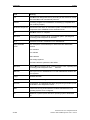
1 A&D DataManagement ................................................................................ 1-7
1.1 Overview .................................................................................................... 1-8
1.2 Which components does ADDM support?................................................. 1-10
1.3 How does A&D DataManagement work? .................................................. 1-11
1.3.1 Hardware connection for fast recovery................................................... 1-11
1.3.2 Backup concept ...................................................................................... 1-14
1.4 Installing A&D DataManagement............................................................... 1-16
1.4.1 Installation from the setup frame ............................................................ 1-18
1.4.2 Installing the product setup..................................................................... 1-23
1.4.3 Installing ADDM Single User .................................................................. 1-25
1.4.4 Installing ADDM Agent............................................................................ 1-25
2 Operating A&D DataManagement .............................................................. 2-27
2.1 User log on................................................................................................. 2-27
2.2 Specifying the plant structure .................................................................... 2-30
2.3 Assigning control components................................................................... 2-32
2.4 Specifying the properties of the control components ................................ 2-35
2.4.1 NCU component ..................................................................................... 2-36
2.4.2 Single axis control MCU ......................................................................... 2-43
2.4.3 S5 Component ........................................................................................ 2-45
2.4.4 S7 Component ........................................................................................ 2-47
2.4.5 Communication modules CP342-5, CP343-1, CP443-1, CP443-5 ........ 2-54
2.4.6 OP, TP and MP operator panels with ProSave ...................................... 2-56
2.4.7 Drive component..................................................................................... 2-59
2.4.8 HMI DOS OP 031 operator panel ........................................................... 2-65
2.4.9 Serial component.................................................................................... 2-66
2.4.10 Path component.................................................................................... 2-68
2.4.11 PCIN component .................................................................................. 2-71
2.4.12 Neutral component ............................................................................... 2-76
2.4.13 SINUMERIK components ..................................................................... 2-84
2.5 HD component ........................................................................................... 2-87
2.5.1 HD Component via network for MS DOS ............................................... 2-87
2.5.2 Creating an ADDM boot disk or USB Flash Drive .................................. 2-93
2.5.3 Adding additional languages to the ADDM boot medium....................... 2-98
2.5.4 Backup and loading with PCU 50 V1 and V2 via the network................ 2-102
2.5.5 Backup and loading with PCU 50.3 via the network............................... 2-107
2.5.6 Creating an ADDM boot medium using PE Builder ................................ 2-109
2.5.7 Backup and loading with PE Builder....................................................... 2-111
© Siemens AG 2011 All Rights Reserved
SIMATIC A&D DataManagement Client - 07/2011
iii
Content
07/2011
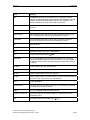
2.6 Transferring data........................................................................................ 2-114
2.6.1 Selecting the transfer in ADDM .............................................................. 2-114
2.6.2 Transfer with the use of multibackups .................................................... 2-117
2.6.3 Cable connections for the transfer.......................................................... 2-119
2.7 Comparison functions ................................................................................ 2-124
2.7.1 Comparing the NCU component ............................................................ 2-126
2.7.2 Comparing the MCU component ............................................................ 2-129
2.7.3 Comparing the drive component ............................................................ 2-131
2.7.4 Comparing the S5 component ................................................................ 2-132
2.7.5 Comparing the S7 CPU .......................................................................... 2-134
2.7.6 Comparing CPs ...................................................................................... 2-137
2.7.7 Comparing OPs ...................................................................................... 2-138
2.7.8 Comparing the path component ............................................................. 2-139
2.8 SIMATIC S7 functions ............................................................................... 2-140
2.8.1 Opening the data with STEP7 software.................................................. 2-140
2.8.2 Displaying blocks and files from a S7..................................................... 2-141
2.8.3 Transferring the configuration to new hardware ..................................... 2-141
2.8.4 Displaying accessible nodes................................................................... 2-142
2.9 Handling of Files/Blocks ............................................................................ 2-143
2.9.1 Display Files/Blocks of a NCU ................................................................ 2-143
2.9.2 Display Files/Blocks of a S5 ................................................................... 2-144
2.9.3 Displaying files and blocks of an HD component ................................... 2-145
2.9.4 Display Files/Blocks of a path component.............................................. 2-145
2.9.5 Export Contents of a Path Component................................................... 2-145
2.9.6 Displaying files and blocks of an SINUMERIK component .................... 2-146
2.9.7 NC-Files to the PCU ............................................................................... 2-146
2.10 Standard functions................................................................................... 2-148
2.10.1 Basic settings........................................................................................ 2-148
2.10.2 Moving menu bars ................................................................................ 2-155
2.10.3 Logging actions (Logfile)....................................................................... 2-155
2.10.4 Entering a user comment...................................................................... 2-157
2.10.5 Printing.................................................................................................. 2-158
2.10.6 Online-Hilfe ........................................................................................... 2-158
2.10.7 The About window ................................................................................ 2-159
2.10.8 Changing icon files ............................................................................... 2-159
2.10.9 Remote maintenance options ............................................................... 2-160
2.11 User management ................................................................................... 2-162
2.11.1 Creating a new group ........................................................................... 2-163
2.11.2 Creating a new user.............................................................................. 2-164
2.12 Archive functions ..................................................................................... 2-165
2.12.1 File and print sharing ............................................................................ 2-165
2.12.2 Archiving functions of the Client ........................................................... 2-166
2.12.3 Archiving ............................................................................................... 2-167
2.12.4 Dearchiving ........................................................................................... 2-168
2.12.5 Displaying the archive content.............................................................. 2-169
2.12.6 Comparing archives.............................................................................. 2-169
2.12.7 Selecting the archive server ................................................................. 2-170
2.12.8 Displaying versions............................................................................... 2-170
2.12.9 Backup and Archive.............................................................................. 2-171
iv
© Siemens AG 2011 All Rights Reserved
SIMATIC A&D DataManagement Client - 07/2011
07/2011
Content
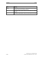
2.13 Job server ................................................................................................ 2-173
2.13.1 General ................................................................................................. 2-173
2.13.2 Opening the Job server ........................................................................ 2-174
2.13.3 Create Job ............................................................................................ 2-174
2.13.4 Confirm Job........................................................................................... 2-176
2.14 Notes and tips .......................................................................................... 2-177
A Appendix ...................................................................................................... A-179
A.1 Glossary .................................................................................................... A-179
© Siemens AG 2011 All Rights Reserved
SIMATIC A&D DataManagement Client - 07/2011
v
Content
vi
07/2011
© Siemens AG 2011 All Rights Reserved
SIMATIC A&D DataManagement Client - 07/2011
07/2011
1 A&D DataManagement
1.1 Overview
1 A&D DataManagement
1
About this Operator Manual
This Software Installation Manual for the A&D DataManagement (ADDM)
application is a part of the ADDM installation CD. It is not available separately.
© Siemens AG 2011 All Rights Reserved
SIMATIC A&D DataManagement Client - 07/2011
1-7
1 A&D DataManagement
1.1 Overview
07/2011
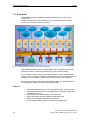
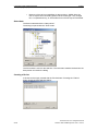
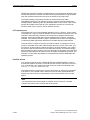
1.1 Overview
A&D DataManagement (ADDM) is the data storage system for your control
components.
ADDM manages the data and programs of the components used in a simple
manner via one uniform operator interface.
Fig. 1-1: Uniform operator interface for all control components
A&D DataManagement gives you independence from configuration tools, data
types and formats. It creates an exact image of your production facility.
Even complex production lines can be easily imaged in clearly understandable
directory trees. The display is based on the Windows Explorer from Microsoft. The
navigation is not oriented on abstract data structures, but on real conditions.
Identical components can be supplied with identical data. The standardization of
the configuration makes service and maintenance easier.
Features
•
•
•
•
•
•
•
1-8
Production-oriented structure: uncomplicated overview, easy to handle
Reduced plant downtimes for replacing defective hardware components
(fast disaster recovery)
Increased security and availability of all data stocks
Works with already existing standard configuration tools
Supports as standard a multitude of components
No special knowledge needed, for example of programming.
© Siemens AG 2011 All Rights Reserved
SIMATIC A&D DataManagement Client - 07/2011
07/2011
1 A&D DataManagement
1.1 Overview
A&D DataManagement increases plant availability
Replacement components are promptly supplied with the relevant data. There is no
time-consuming parameterizing and configuring.
In this context, it is irrelevant whether you need to copy over individual files or
complete hard disk partitions in the form of a compressed image file (imaging).
High safety level with A&D DataManagement - company wide
A&D DataManagement allows you to store data centrally on servers and mass
storage systems. You can therefore integrate your entire data stock into highly
available client-server architectures and fault tolerant online storage. This enables
the plant control to provide the highest possible safety standards for your data.
A&D DataManagement provides extensive options for drive-independent
DataManagement:
• Data can be stored online on a server.
• Removable disks may be used.
• Loading data and settings after component replacement.
• Backup of complete hard disks or hard disk partitions (imaging).
• Restoration of hard disks or partitions from an image file.
• Reloading to an unpartitioned and unformatted hard disk.
• Logging of all modifications in a logbook.
© Siemens AG 2011 All Rights Reserved
SIMATIC A&D DataManagement Client - 07/2011
1-9
1 A&D DataManagement
1.2 Which components does ADDM support?
07/2011
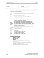
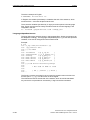
1.2 Which components does ADDM support?
Supported hardware components
All the relevant data and programs of the components, which are integrated into
ADDM, can be managed, backed-up and loaded. ADDM uses the existing
connections and communications.
NCU
SINUMERIK 840D/840Di/810D powerline, PLC-Data via S7-CPU
MCU
MCU 172A, PLC-Data via S7-CPU
S5
90U, 95U, 100U via AS511; 115U, 130W, 130WB, 135U,
155U via AS511 or SINEC H1
S7
S7-300, S7-400, WIN AC, WIN AC RTX
C7
C7-623, C7-626, C7-633, C7-634, C7-635 OP Mono, C7-635 TP B Mono
CPs
CP342-5, CP343-1,CP443-1, CP443-5
OPs
For supported OPs, read the ProSave documentation, please.
MPs
For supported MPs, read the ProSave documentation, please.
TDs/TPs
For supported TDs/TPs, read the ProSave documentation, please.
Drives
SIMODRIVE 611 universal HRS/universal E HRS/digital via NCU,
SIMODRIVE POSMO A/CD/CA/SI
COMBIMASTER, MASTERDRIVES and SIMOREG via DriveES
HMI DOS
DOS-Package for OP 031
Serial
interface
Path
V.24-Interface (RS-232 C)
PCIN
HPU, OP 030, MMC 100, MMC 100.2
HD
Complete hard disks or partitions
PCIN
HPU, OP 030, MMC 100, MMC 100.2
Neutral
Neutral component
Folders, Files
Supported software tools
•
•
•
•
•
•
•
•
•
1-10
IBN611D, Mini-DNC
SimoComU/A
MCU-PIT
STEP 7, NCM
ProTool (others SIMATIC HMI OPs in preparation)
ProSave for OPs
Transline 2000 Setup Tool for HMI DOS and HMI PRO
General V.24 transfer (RS-232 C)
General software tools with an open interface
© Siemens AG 2011 All Rights Reserved
SIMATIC A&D DataManagement Client - 07/2011
07/2011
1 A&D DataManagement
1.3 How does A&D DataManagement work?
1.3 How does A&D DataManagement work?
A&D DataManagement manages the data and programs existing in the production
facilities in a uniform plant structure. To do this, it represents the structure of your
production facility as a directory tree in the interface, which is based on the
WINDOWS Explorer. You manage the data and programs existing for each control
component via this plant structure–and backup or load as required.
For this ADDM uses the existing standard software tools for the components. You
can thus manage the data both with the standard software tool and with the A&D
DataManagement software.
In order to enable fast disaster recovery, defective components are replaced by
new ones. Then the previous parameterization is loaded into the component
concerned with ADDM.
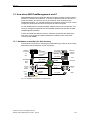
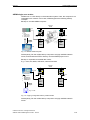
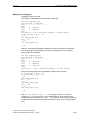
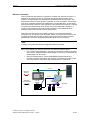
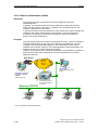
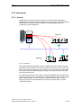
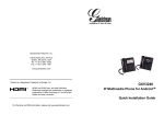
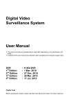
1.3.1 Hardware connection for fast recovery
The hardware connection for restoring the parameterizing is made in various ways,
depending upon the defective control component.
CP342-5
SIMATIC
S7-300/400
C7
S IM ATIC
S 7-300
SIMATI C
S7-30 0
CPs
SIMATIC
S7-300
SINUMERIK
NCU
MCU
Drives
611U
POSMO
PCU
HD
Path
HMI PRO
V.24 Serial
PROFIBUS
Ethernet
MPI
PROFIBUS
PROFIBUS
Ethernet
MPI / BTSS /
PROFIBUS
V.24 Serial
ADDM
Parallel
V.24 Serial
PROFIBUS
SINEC H1
AS 511
Parallel
TCP/IP
V.24 Serial
SIMATIC
Operator
Panels
PCIN
HMI DOS
SIMATIC
S5
Serial
Fig. 1-2: Hardware connections for fast recovery
© Siemens AG 2011 All Rights Reserved
SIMATIC A&D DataManagement Client - 07/2011
1-11
1 A&D DataManagement
1.3 How does A&D DataManagement work?
07/2011
MCU, NCU, S7-CPU, drives
MCU, NCU and S7-CPU are loaded directly over the MPI connection.
Moreover, NCUs, drives and S7-CPUs can also be addressed via PROFIBUS
links.
Operator Panels
All operator panels
• OPs
• TDs
• TPs
• MPs
are connected over the serial interface (RS-232-C).
A defective operator panel is replaced by a new one.
If necessary, connect the operator panels to be loaded via the serial interface to
the ADDM computer.
PCIN
The operator panels for SINUMERIK HPU, OP 030, MMC100 und MMC100.2 are
loaded via serial interface. Other operator systems of SINUMERIK are PC-based
operator panels with implemented hard disks.
S5-CPU
The S5-CPU can be reached via SINEC H1 or the serial interface AS511. An
appropriate CP is needed in the rack of the SIMATIC S5 and in the PG/PC for
communication via H1.
HMI DOS
The HMI DOS operator interface is linked to the ADDM computer via the Interlink
(parallel or serial interface).
Hard disks
Complete hard disks are loaded under ADDM via the parallel interface (not under
Windows NT 4.0 or Windows 2000 and Windows XP) or via the TCP/IP network.
Neutral component
The neutral component allows integrating miscellaneous software tools by an easy
way into ADDM. This software tools need an interface for the communication with
ADDM.
Further, the neutral component allows the integration of prepared operating system
calls. You can thus, for example, integrate FTP.
SINUMERIK component
The SINUMERIK component allows ADDM to generate NC and PLC series startup
files.
1-12
© Siemens AG 2011 All Rights Reserved
SIMATIC A&D DataManagement Client - 07/2011
07/2011
1 A&D DataManagement
1.3 How does A&D DataManagement work?
Miscellaneous
Even older control systems and non-Siemens systems can be connected to ADDM.
In such cases, the crucial factor is whether the systems use standard transfer
mechanisms. Older SINUMERIK systems such as the 3/8, 810, 820, 850 and 880
systems use a serial interface without a protocol for data output. Machine data, for
example, are output via this interface. ADDM can receive and store data with the
serial component. After the data exchange, this data can be transferred to the
systems again.
Systems such as SINUMERIK 840C have a PC, which can be backed up and
loaded with the DOS drivers Interlink and Interserv. These drivers were
components of the Microsoft MSDOS operating system and are therefore subject
to the relevant licensing laws. For this reason, these drivers are not supplied with
ADDM.
If these drivers are present on the backup computer, ADDM can recognize this
serial or parallel coupling and backup and reload data via the path component.
© Siemens AG 2011 All Rights Reserved
SIMATIC A&D DataManagement Client - 07/2011
1-13
1 A&D DataManagement
1.3 How does A&D DataManagement work?
07/2011
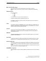
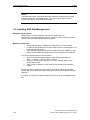
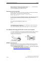
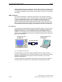
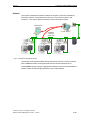
1.3.2 Backup concept
ADDM supports different hardware configurations for backing up configuration and
system data:
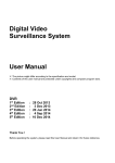
• ADDM (client) runs on a mobile network computer, which stores the
backup data on a central server. Via this computer it is possible to transfer
the data between hardware components and server.
• ADDM (client or agent) runs on stationary network computer (e.g. operator
panels) and is connected to the automation component. The computer has
also access to the server in the same way as the mobile computer.
The following applies to both solutions:
The ADDM project and the STEP7 project must lie on a common drive for both
solutions!
ADDM Agent in stationary network computers takes the communication with the
automation components. That means an agent can be installed on an operator
panel. All data transfer functions via network are possible without a complete client
installation is necessary on the operator panel.
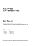
ADDM on a network computer
Ethernet
TCP/IP
MMC
MMC
Server
Central
Data storage
Archiving
Versions
STEP7 Project
ADDM Project
V.24
PG
MPI
OPI
OPI
840D
NC
840D
NC
PLC
PLC
Drive
Drive
V.24
MPI
Local
PG functions
A&D Data
Management
Fig. 1-3: ADDM as a network station
1-14
© Siemens AG 2011 All Rights Reserved
SIMATIC A&D DataManagement Client - 07/2011
07/2011
1 A&D DataManagement
1.3 How does A&D DataManagement work?
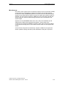
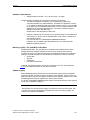
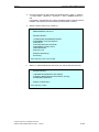
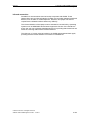
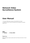
ADDM single user version
ADDM runs on a PC directly on the automation system. Here, the computer is not
integrated into a network. In this case, ADDM supports the following backup
concepts:
Backup on a mobile ADDM computer.
Ethernet
TCP/IP
MMC
PC
Local
Data
Management
STEP7 project
ADDM project
V.24
V.24
ADDM
project
MMC
OPI
OPI
840D
NC
840D
NC
PLC
PLC
Drive
Drive
MPI
PG
Fig. 1-4: Mobiler ADDM computer
Subsequently, link the mobile backup computer to a highly available network
server, and transfer the STEP7 directory and the ADDM project on to it.
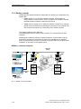
Backup on a portable removable data carrier
E.g.: LS120, CD, MOD, USB stick, external hard disk.
Ethernet
TCP/IP
MMC
MMC
PG / FI 45
Local
PG functions
Data
Management
STEP7 project
ADDM project
MPI
ADDM
project
V.24
V.24
OPI
OPI
840D
NC
840D
NC
PLC
PLC
Drive
Drive
MPI
E.g.: LS120
Fig. 1-5: Copying configuration data to portable media
Subsequently, link the mobile backup computer to a highly available network
server.
© Siemens AG 2011 All Rights Reserved
SIMATIC A&D DataManagement Client - 07/2011
1-15
1 A&D DataManagement
1.4 Installing A&D DataManagement
07/2011
Notice
Complete paths (path component) and hard disks (HD component) are always
backed up directly in the ADDM project. The projects can therefore quickly
become too large for removable data carriers.
1.4 Installing A&D DataManagement
Hardware requirements
ADDM Client is a 32 bit application requiring an MS Windows XP.
The hardware requirements depend on the operating systems used and are also
stated for the use of the relevant operating system.
Memory requirement
•
•
•
ADDM requires approx. 40MB free storage space on your hard disk.
In addition, MS Windows XP require storage space for the swap-file on the
hard disk (typically drive C:)
Other Windows applications running simultaneously with ADDM (e.g. MS
Word) require additional storage space on the hard disk for the swap file.
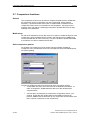
You set the required swap file size as follows:
1. Open the System Properties dialog via the MS Windows task bar:
Start → Settings → Control Panel → System.
2. Select the "Performance” tab and click on the "Change” button in the
Virtual Memory field.
3. Set the "Size of swap file” to the value recommended by the operating
system.
Ensure that there is sufficient storage space on the drive with the project data.
Project data can be destroyed if the storage space becomes insufficient during an
operation.
If possible, do not store the project data on the same drive as the Windows-swap
file.
1-16
© Siemens AG 2011 All Rights Reserved
SIMATIC A&D DataManagement Client - 07/2011
07/2011
1 A&D DataManagement
1.4 Installing A&D DataManagement
Software requirements
•
ADDM must have STEP 7 V5.1, service pack 1 or higher.
Further software packages are required for individual components:
• The MCU172A (MCU component) can be backed up, loaded and
compared via MPI (only FM-POS data). The MCU-PIT application version
4.1 or higher is needed to load and backup the MCU172A. It is not possible
to run MCU-PIT and ADDM simultaneously. However, data backed up with
ADDM can be processed with MCU-PIT. The same conditions apply to
ADDM in connection with MCU-PIT.
Please refer to the description of MCU-PIT.
•
Interlink is required for the transfer to the operator panel OP 031(HMI DOS
component). To do this, the AUTOEXEC.BAT must contain a reference to
the Interlink directory.
For new PGs this is: C:\WINDOWS\COMMAND\OLDDOS.
Interlink is only available under MS Windows 9x, not under other MS
Windows operating systems.
Backing up OPs, TPs und MPs via ProSave
ADDM enables OPs, TPs and MPs to be backed up and loaded with ProSave.
ADDM installs the ProSave software on the back up computer and uses the
ProSave functions. The data are backed up and loaded according to the selected
settings. The following data can be transferred, irrespective of the OP selected:
• All OP data
• Recipes
• Passwords
• Firmware/configuration
However, the backed up data cannot be processed by ProTool, see subsection
2.4.6 for detailed information on the use of ProSave.
Update registry
A&D DataManagement makes entries in the Windows registry during installation.
These entries are required for proper operation of the software. If the PC works in
different modes (e.g. with and without a network) with different registries, then A&D
DataManagement must be registered for both of these modes.
To do this, install A&D DataManagement again in the same directory in the second
mode, just to update the registry.
Note
Alternatively you can export the registry and import it into the second mode. This
procedure is only recommended for experienced users as a faulty registry can
destroy your Windows installation.
© Siemens AG 2011 All Rights Reserved
SIMATIC A&D DataManagement Client - 07/2011
1-17
1 A&D DataManagement
1.4 Installing A&D DataManagement
07/2011
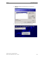
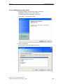
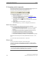
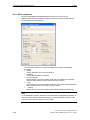
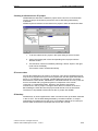
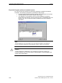
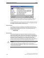
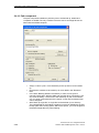
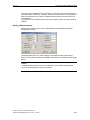
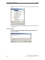
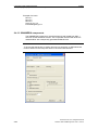
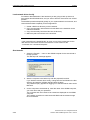
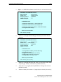
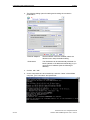
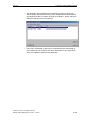
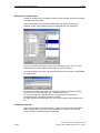
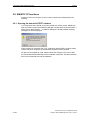
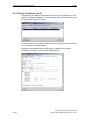
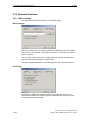
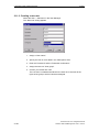
1.4.1 Installation from the setup frame
1. Start the installation of the setup frame by calling "setup.exe” on the
CD supplied.
Follow the instructions displayed on the screen.
2. Select the desired language version for A&D DataManagement during
the setup.
For using the required language in ADDM, the additional setting must
be done in "SIMATIC Manager Step 7” menu Option → Customize…
→ Language.
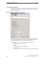
3. Then enter the user information User Name and Organization Name.
1-18
© Siemens AG 2011 All Rights Reserved
SIMATIC A&D DataManagement Client - 07/2011
07/2011
1 A&D DataManagement
1.4 Installing A&D DataManagement
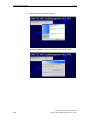
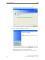
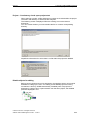
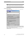
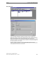
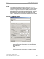
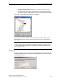
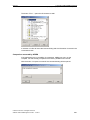
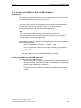
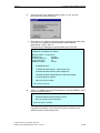
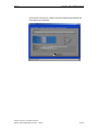
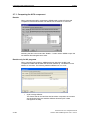
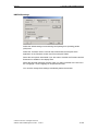
4. ADDM offers different components which you can select for
installation.
5. During the setup, select the requested language version.
© Siemens AG 2011 All Rights Reserved
SIMATIC A&D DataManagement Client - 07/2011
1-19
1 A&D DataManagement
1.4 Installing A&D DataManagement
07/2011
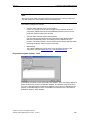
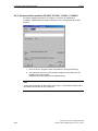
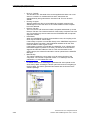
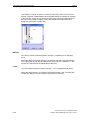
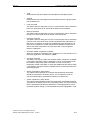
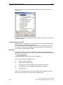
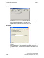
6. Select "Next >" to continue the setup.
7. Read the installation notes. Press "Next" to continue the setup.
1-20
© Siemens AG 2011 All Rights Reserved
SIMATIC A&D DataManagement Client - 07/2011
07/2011
1 A&D DataManagement
1.4 Installing A&D DataManagement
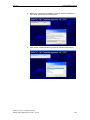
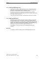
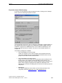
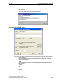
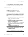
8. Before you continue the installation, carefully read the conditions of
the license agreements and accept them.
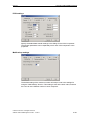
9. With "Install”, ADDM installs the previously selected components.
© Siemens AG 2011 All Rights Reserved
SIMATIC A&D DataManagement Client - 07/2011
1-21
1 A&D DataManagement
1.4 Installing A&D DataManagement
07/2011
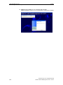
10. ADDM is fully installed on your computer after this step.
ADDM installation informs you if it’s necessary to reboot the computer.
1-22
© Siemens AG 2011 All Rights Reserved
SIMATIC A&D DataManagement Client - 07/2011
07/2011
1 A&D DataManagement
1.4 Installing A&D DataManagement
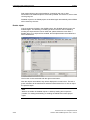
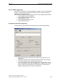
1.4.2 Installing the product setup
1. Start the installation of the product setup by calling file
ADDM/Disk1/setup.exe on the CD supplied.
Follow the instructions displayed on the screen.
Press “Next >“ to continue the setup.
2. Check your settings.
Press “Install“ to start the installation process.
© Siemens AG 2011 All Rights Reserved
SIMATIC A&D DataManagement Client - 07/2011
1-23
1 A&D DataManagement
1.4 Installing A&D DataManagement
07/2011
3. The installation progress is displayed during the installation.
4. Press “Complete“ to terminate your installation..
5. ADDM is fully installed on your computer after this step.
ADDM installation informs you if it’s necessary to reboot the computer.
1-24
© Siemens AG 2011 All Rights Reserved
SIMATIC A&D DataManagement Client - 07/2011
07/2011
1 A&D DataManagement
1.4 Installing A&D DataManagement
1.4.3 Installing ADDM Single User
If you want to work with the ADDM single-user version, you must authorize the
ADDM Client. The necessary program is available on the "ADDM Single User"
disk, which is supplied together with the single-user license.
Authorization is carried out with AuthorsW, as already known from STEP7.
Unrestricted working with the ADDM single-user version is possible only when this
authorization has been carried out.
In the case of client server operation, the authorization of the server is checked.
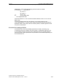
1.4.4 Installing ADDM Agent
ADDM Client-server or Single User version have the possibility to communicate
with several ADDM Agents. On stationary computers (e.g. operator panels) in
machines the memory space is mostly limited. An ADDM Client needs the STEP7software in the background. This complete installation on operator panels is not
possible. In this case the ADDM Agent will be installed on the operator panel. The
ADDM Agent is the helping hand of the ADDM Client/Single User.
The installation is done in the same way as the ADDM Client/Single User
installation.
References
For details see Software Installation Manual "A&D DataManagement Agent".
© Siemens AG 2011 All Rights Reserved
SIMATIC A&D DataManagement Client - 07/2011
1-25
1 A&D DataManagement
1.4 Installing A&D DataManagement
1-26
07/2011
© Siemens AG 2011 All Rights Reserved
SIMATIC A&D DataManagement Client - 07/2011
07/2011
2 Operating A&D DataManagement
2.1 User log on
2 Operating A&D DataManagement
2
The operation of ADDM software is divided into four main steps:
• Imaging the plant structure
• Assigning hardware components
• Defining properties of the hardware components
• Backing up and loading configuration data.
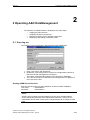
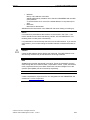
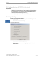
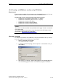
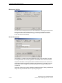
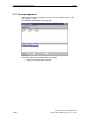
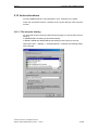
2.1 User log on
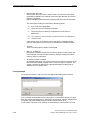
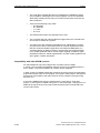
The following "Log-on information” dialog appears after ADDM starts.
1. Enter "User name” and "Password”.
2. Disable the "Use external server” option in the single station version so
that the local user management is accessed.
This option is automatically enabled in the client-server installation.
3. The name of the server on which the user management runs appears in
the "User server” field.
Starting ADDM for the first time
Enter the following when you start ADDM for the first time after installation:
User name
"Administrator"
Password
"Administrator"
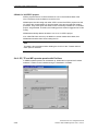
Notice
After the user manager has been started for the first time, the administrator
should change the password of the administrator. Moreover, more than one
administrator should have access rights. Lost passwords can no longer be read
back.
© Siemens AG 2011 All Rights Reserved
SIMATIC A&D DataManagement Client - 07/2011
2-27
2 Operating A&D DataManagement
2.1 User log on
07/2011
You can now create new users and user groups and assign them appropriate
rights, see section 2.11 User management.
Then restart ADDM and log yourself on as a newly created user.
Notice
You cannot create your own projects in ADDM until you have created a new user
and then restarted. The administrator can only manage users, he/she cannot edit
ADDM projects. The administrator has all rights as standard.
In the single user version, the user management can be deactivated via the menu
Tools → Settings.
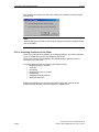
Logging a new user on
Select the User → Log on... menu to log yourself on as a new user without leaving
the ADDM application.
The above Log-on information dialog appears, and you can log yourself on as a
new user to work with ADDM.
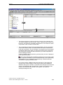
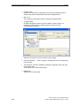
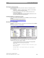
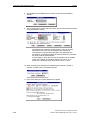
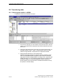
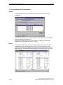
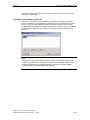
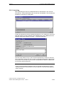
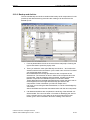
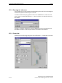
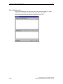
Basic information about the human-machine interface
The ADDM interface is subdivided into three main windows. The window areas can
be moved respectively to other with the mouse (see arrow). All actions in ADDM
are performed by operations in this interface.
The action may take place via the menu bar or via the buttons. As a result of the
selection in the windows, some functions may be grayed out. This means that
these functions are disabled.
The actions possible with a particular selection are shown in black script in the
menus or their buttons are shown in color. If the mouse pointer is held still over a
button, a text appears alongside the mouse pointer explaining the button"s
function.
2-28
© Siemens AG 2011 All Rights Reserved
SIMATIC A&D DataManagement Client - 07/2011
07/2011
2 Operating A&D DataManagement
2.1 User log on
•
The left-hand window contains the directory structure of a production line.
The data is assigned via this structure. Areas, subareas and machines can
be set up. The machines constitute the lowest level. The machines contain
components, which contain the actual data
•
The components are stored in the right-hand window. These components
contain the backed up data. The data transfer information is also stored
under the components. This is necessary if a component can be accessed
via different transmission paths. As well as the names of the components,
this window also contains the data of the back up, the last comparison or
the last loading procedure.
If data are linked to the component by pointers (links), the link is displayed
in the right-hand window.
This symbol indicates that an additional safety back up has been made
in the component in addition to the normal data backup. This is particularly
advantageous if it is not desired that automatically scheduled backups
overwrite the originally backed up data.
•
In the lower window, ADDM provides the information of the logbook file
(log file) of the current session. All the actions performed in ADDM are
entered in the log file. Transfers, comparisons and changes in the structure
are thus recorded with date, time and user. If errors occur during a data
transfer, then these are also stored in the log files. This makes a
subsequent diagnosis easy.
© Siemens AG 2011 All Rights Reserved
SIMATIC A&D DataManagement Client - 07/2011
2-29
2 Operating A&D DataManagement
2.2 Specifying the plant structure
07/2011
Note
ADDM uses the associated communication mechanisms to communicate with the
various components. Information and error messages are reported by the drivers
to ADDM and displayed on the human-machine interface. While doing so,
corresponding error codes are provided for detailed diagnosis by SIEMENS.
The following sections in this documentation contain more detailed information about
operation.
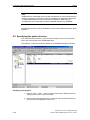
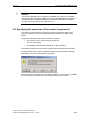
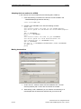
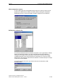
2.2 Specifying the plant structure
You model the plant structure of your production facility in the form of a directory
tree in the main window of the ADDM application.
The operation of the main window is based on the WINDOWS Explorer interface.
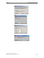
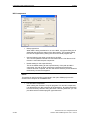
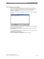
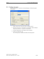
Creating a new project
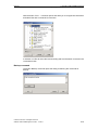
1. Select the File → New... menu to create a new project. ADDM creates an
empty project with the name "Unnamed".
2. Rename the unnamed project as, for example, Plant by double clicking or
using the Object properties context menu.
2-30
© Siemens AG 2011 All Rights Reserved
SIMATIC A&D DataManagement Client - 07/2011
07/2011
2 Operating A&D DataManagement
2.2 Specifying the plant structure
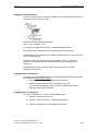
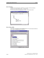
Imaging the plant structure
In order to image the plant structure in ADDM, create a corresponding directory for
each level of your production facility.
Construct it using the following hierarchy:
Plant – Area – Subarea – Unit.
For example, the highest level, "Plant”, represents the entire works.
The "Areas” level contains the New hall, Old hall and the Warehouse.
In this example, the "Subarea” level consists of production line 1, production line 2
and the stacking facility.
The lowest level of the tree represents the individual "Units” (or machines).
Elements on the lowest level are also referred to as physical assets in this
connection.
The designation of each tree entry can be freely selected in the "Object
properties"context menu.
Copying/insert a subproject
You spool a complete ADDM project onto an exchangeable data carrier as follows,
see subsection,1.3.2 Backup concept:
1. Select the Project functions → copy/insert subproject.
2. Select the target directory on the removable data carrier.
This ensures that the data carrier contains the ADDM project (plant
topology) and the STEP7 projects.
Copying/insert a subproject
You copy a subproject or a unit as an other ADDM project:
1. Select the subproject or the unit.
2. Select the Project functions → copy/insert subproject.
3. Select the target/source in the target/source project.
© Siemens AG 2011 All Rights Reserved
SIMATIC A&D DataManagement Client - 07/2011
2-31
2 Operating A&D DataManagement
2.3 Assigning control components
07/2011
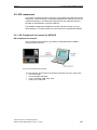
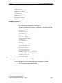
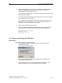
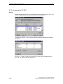
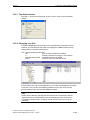
2.3 Assigning control components
After imaging the plant structure, the control components have be assigned to the
units. The various control components are located within the unit.
The various control components are located within the unit:
You assign a new control component to a unit as follows:
1. Select the relevant unit.
2. Click on the component button in the button bar on the right.
3. Choose one of ADDM supported components, see chapter 1.2 Which
components does ADDM support?.
4. For example, click on the
button to assign a S7-CPU.
With double click on the inserted S7-CPU "Properties of the component”
dialog opens.
5. Assign a name to the new component, e.g. "S7-CPU".
6. Click on "OK".
The new component, e.g. "S7-CPU”, is assigned to the relevant unit.
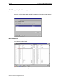
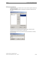
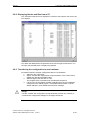
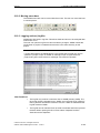
Details of each component
The list on the right displays additional details about each component:
• The Component field contains the freely allocated name of the component
• The Type field contains the component type
• The Link field shows the hardware link of the component to the ADDM
computer.
• The Comparison time field shows the timestamp of the last comparison.
• The Loading time field shows the timestamp of the last load.
• The Backup time field shows the timestamp of the last backup.
• The Data pointer field shows the paths of the pointered projects.
• The user sees immediately if, for example, a S7 component is not pointered.
You sort the lists according to the currently selected field with the View → Sort
menu.
You can save the current sort with the View → Save menu.
Editing a project
You can cut and paste components, units and whole areas.
Components, which are no longer needed, can be deleted. To delete, ADDM
moves the components into the WINDOWS Recycle bin. The linked data stocks
are not deleted.
Note
If you have made changes to the plant structure, you must first save them before
you can load or backup the corresponding control components.
2-32
© Siemens AG 2011 All Rights Reserved
SIMATIC A&D DataManagement Client - 07/2011
07/2011
2 Operating A&D DataManagement
2.3 Assigning control components
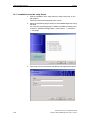
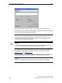
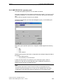
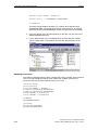
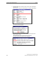
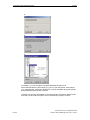
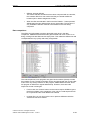
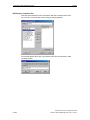
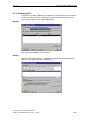
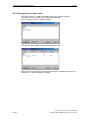
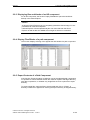
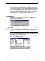
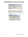
Project – Consistency check upon project start
When opening a project, all file and directory entries are checked within the project.
The files in the directory or directories are analyzed.
The following screen is displayed if files are existing, but not the relevant
directories.
You can choose whether you wish to delete the file or create a corresponding
directory.
Superfluous directories for which there is no file within the project are deleted.
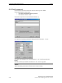
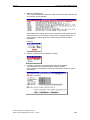
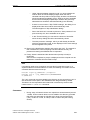
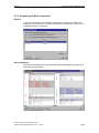
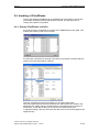
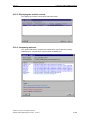
Disable objects for editing
Before control components can be assigned or changed the area or unit must be
disabled for editing by the user. On creating a new ADDM project the locking
mechanism is done by ADDM automatically. Disabled parts of a project are
displayed in a green colour. Opens another user the same project, the disabled
parts are displayed in red.
© Siemens AG 2011 All Rights Reserved
SIMATIC A&D DataManagement Client - 07/2011
2-33
2 Operating A&D DataManagement
2.3 Assigning control components
07/2011
Red marked objects cannot be handled or changed by the user. A data
transmission into disabled objects is blocked by ADDM. The reason is, that no data
can be going lost.
Disabled objects in an ADDM-project are enabled again automatically when ADDM
will be closed by the user.
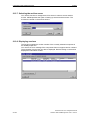
Enable objekt
If the changes are finished in the ADDM-project, the disabled objects have to be
enabled again. The disabling or enabling is done in the tree view of ADDM by
marking the object with the mouse. After that, please select the menu Edit →
Enable object. If an object will be enabled, also all objects below the enabled one
will be enabled too.
The function is also reachable with the right mouse button.
After the objects are enabled, they will be displayed in normal colour. The red or
green indication will be switched off and data transmissions from or into an object
are possible again.
Note
Without an enable off disabled objects no backup, loading and compare is
possible. For setting the disabling or enabling the ADDM user needs project
rights.
2-34
© Siemens AG 2011 All Rights Reserved
SIMATIC A&D DataManagement Client - 07/2011
07/2011
!
2 Operating A&D DataManagement
2.4 Specifying the properties of the control components
Attention
The function "Disable object for editing" is available from version 5.2 of ADDM.
On using of minor versions of ADDM, an access to disabled objects is possible. A
data transmission into disabled objects in this case is not blocked. The higher
security level for the data is only valid with V5.2.
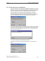
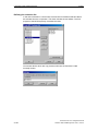
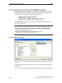
2.4 Specifying the properties of the control components
You reach the "Properties of the component” dialog by double clicking on the
relevant component, or via the "Object properties” context menu (right mouse
button).
The general statements about each component comprise:
• The internal "name” of the particular component.
This can be changed.
•
An additional "Remark” with a maximum of 255 characters.
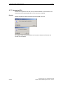
The specific properties of each control component are described in the following.
In the properties of the control components options may be activated. Following
message box occurs on activating such an option
If such an option is activated, the component is visible in a minor version of ADDM.
But working with the component is not possible with any minor version.
© Siemens AG 2011 All Rights Reserved
SIMATIC A&D DataManagement Client - 07/2011
2-35
2 Operating A&D DataManagement
2.4 Specifying the properties of the control components
07/2011
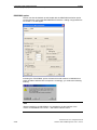
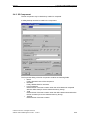
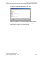
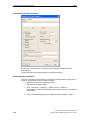
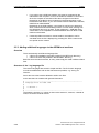
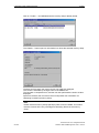
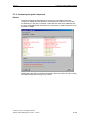
2.4.1 NCU component
The NCU SINUMERIK 810D/840D/840Di machine tool control can be
loaded, backed up and compared. Additional to these functions safety backups
can be made into this component.
The Properties of the NCU component dialog box contains the following
information:
• Name:
Freely allocated name of the component.
• Remarks:
Freely editable field for user texts.
• Last comparison
Date and time of the last occasion when the online data was compared
with the offline data (for source data and memory dump).
• - load
Date and time of the last occasion when the offline data was transferred to
the controller (for source data and memory dump).
•
- backup
Date and time of the last occasion when the NCU data was backed up.
Note
In the ADDM list overview, the date of the last backup is displayed by definition in
the source data. Please note that backups are never performed as source data.
For this reason, this time stamp is not provided.
2-36
© Siemens AG 2011 All Rights Reserved
SIMATIC A&D DataManagement Client - 07/2011
07/2011
2 Operating A&D DataManagement
2.4 Specifying the properties of the control components
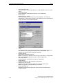
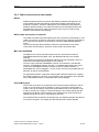
•
MPI/OPI
MPI (or OPI) address of the NCU
ADDM subsequently creates a link to the NCU SINUMERIK with the MPI
(OPI) address.
A communication error occurs if the stated address is not present (error
286).
• Baud rate
Baud rate for the transfer.
ADDM stores the information in the "MMC.INI" file when loading or backing up.
Notice
It is essential to parameterize the interface on the PG/PC in the Tools → Set
PG/PC interface menu before transferring via MPI, OPI and PROFIBUS. This
resetting does not take place automatically.
It is preferable to load and backup the NCU over the MPI interface. If you use the
OPI interface, you must still change to the MPI interface to transfer the entire S7
data.
Caution
Check the MPI address before starting the download. If the MPI address is not
set correctly, the data may be transferred to the wrong hardware.
Note
ADDM backs up all the data stored in the NCU. These are essentially machine
data, setting data, drive machine data, compensation values, cycles, subroutines,
main programs and work piece data. Data which has been swapped out to the
operator panel (MMC) has to be backed up separately.
Note
Create a separate S7 object for an S7 PLC integrated into the SINUMERIK, see
subsection 2.4.4 S7 Component.
© Siemens AG 2011 All Rights Reserved
SIMATIC A&D DataManagement Client - 07/2011
2-37
2 Operating A&D DataManagement
2.4 Specifying the properties of the control components
07/2011
PROFIBUS option
The NC can also be backed up and loaded with the PROFIBUS activation option
via the CP342-5 or the integrated PROFIBUS interface. Loading is supported from
CP version 1.31 and higher.
Activating the "PROFIBUS” option will mean that older versions of ADDM will no
longer be able to edit the NCU component. Accordingly, you receive the following
warning:
Note
Before transferring via PROFIBUS, it is essential to set the interface of the
PG/PC to PROFIBUS in the Tools → Set PG/PC interface menu.
2-38
© Siemens AG 2011 All Rights Reserved
SIMATIC A&D DataManagement Client - 07/2011
07/2011
2 Operating A&D DataManagement
2.4 Specifying the properties of the control components
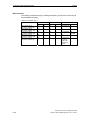
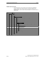
NCU adresses
Table 2-1: Default settings of the bus addresses
Connection
OPI
MPI
OPI
MPI
SW version
V 3.4.07
V 3.4.07
ab V 3.5
ab V 3.5
NCU address
13
13
13
3
PLC address
13
2
13
2
Baudrate
1.5 mbaud
187.5 kbaud
1.5 mbaud
187.5 kbaud
From NCU software version 3.5 and higher, the address of the NCU is
automatically set to PLC-ADR + 1 when the PLC address is changed.
Example:
If the PLC address is changed to 8, the NCU is given the address 8 + 1 = 9 from
the perspective of the MPI. From the perspective of the OPI, the address of the
NCU remains 13, but it can also be changed.
Enter the correct NCU address in the Properties of the NCU component dialog.
Tips for the NCU
In addition to the NC, the NCU component also contains an S7-PLC. The memory
addresses of the S7-PLC are determined by the data of the NCU. Therefore, when
loading the NCU, load the NCU first and then the S7-CPU.
The communication between the NCU and its components requires resources. The
number of these resources is limited. So, if all resources are occupied, ADDM may
send a communication error message. In this case, one can release resources by
removing the operator panel plug (only on point to point coupling between ADDM
computer and NCU).
Attention
During the operation of a NCU, data can be changed by the operator or the by
the control itself. In this case a started data transfer could be interrupted with
communication errors, because an access from ADDM is blocked by the NCU. If
a communication error occurs, the backup has to be repeated absolutely. If not,
the changed data in the NCU are not backed up.
In order to backup, load or compare an NCU, all channels must be in the RESET
state. If this is not the case, then this can result in inconsistent data. If all of the
channels are in the RESET state, then start with the backup operation. The
progress dialog box showing the NC backup operation is always shown. This
means that every operator can see that presently a backup is being made. If not
all of the channels are in the RESET state, then an error message is returned to
the calling program (Agent or ADDM Client) and displayed.
If the backup task is controlled by the job, then the job is interrupted with error
state -2. This means that the job is repeated after a pre-set time. If the maximum
number of repeats has been reached and the NCU has still not been backed-up,
the job is terminated and the next time that it will be executed is calculated. In
this case, the NCU was not backed-up in the backup cycle that expired.
© Siemens AG 2011 All Rights Reserved
SIMATIC A&D DataManagement Client - 07/2011
2-39
2 Operating A&D DataManagement
2.4 Specifying the properties of the control components
07/2011
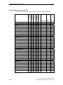
NCU versions
The following restrictions apply to loading and backing up the NCU component via
the PROFIBUS coupling:
Table 2-2: Modules used
Modules used
NCU 573 4.03.12
CP 342-5, release 50
NCU 573 4.03.12
CP 342-5, release 130
NCU 571 3.06.11
CP 342-5, release 120
NCU 571 3.07.14
CP 342-5, release 130
NCU 571 3.07.14
CP 342-5, release 50
2-40
MPI
load
backup
OPI
load
backup
PROFIBUS
load
backup
Not possible
Not possible Not
possible
Communica
tion error
1090, red
LED CF lit
on NC
© Siemens AG 2011 All Rights Reserved
SIMATIC A&D DataManagement Client - 07/2011
07/2011
2 Operating A&D DataManagement
2.4 Specifying the properties of the control components
Multibackup option
The Multibackup option enables additional backups to be made in ADDM to the
normal data backup. This is useful when the system has been modified. In this
case, the data change very frequently. The original data are retained and all the
steps in the modifications can be backed up.
When Multibackup is activated, the number of back ups to be stored by ADDM can
be specified in the Max. no. of backups input box. ADDM takes this specification
into consideration when backing up, and saves a new, separate back up. If the
max. no. of backups is reached, the data starts to be saved in the oldest backup.
This old data is then overwritten. Up to 99 backups can be stored in ADDM in this
way. (Please also refer to Subsection 2.5.2 Creating an ADDM boot disk or USB
Flash Drive).
Routing via agent option
With the option "Routed via agent” the NCU is also connectable via a network
computer installed with ADDM Agent. For that, the name or the TCP/IP-address of
the computer with ADDM Agent has to be declared. To the Agent computer
connected is the real component. In case of a NCU it could be the operator panel
of the SINUMERIK.
© Siemens AG 2011 All Rights Reserved
SIMATIC A&D DataManagement Client - 07/2011
2-41
2 Operating A&D DataManagement
2.4 Specifying the properties of the control components
07/2011
Only NC programs
If the checkbox "Only NC programs” is activated, instead of the classic backup (all
NCU data is saved), only NC programs are backed-up, loaded and compared.
Caution
If you change between the classic, complete backup and only backing-up NC
programs – or vice versa – then all of the previous backups that were made are
deleted.
We recommend that you only backup in the reset state. The reason for this is that
backups carried-out during production can result in data inconsistency!
This is the reason that the checkbox Save only in the reset state is set as
standard.
When the "Directory selection” button is pressed, the "NCU directory selection”
dialog box is opened.
2-42
© Siemens AG 2011 All Rights Reserved
SIMATIC A&D DataManagement Client - 07/2011
07/2011
2 Operating A&D DataManagement
2.4 Specifying the properties of the control components
Here, a checkbox is used to select which directories on the NCU should be taken
into account when backing-up.
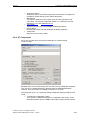
2.4.2 Single axis control MCU
The single axis control MCU 172A has an integrated position control
and its own S7-CPU.
An MCU object is set up to manage the data for position control and drive. The
machine and drive data, the NC programs, the data for the set-up mode and the
tools offsets are stored in the MCU object which has been set up. The integrated
S7-CPU must be managed via an S7 component. The MCU 172A can be loaded,
backed up and compared.
Note
The MCU-PIT V4.1 application must be installed on the backup computer in order
to use this function with the "MCU 172A". The MCU_PIT runs only under
Windows 9x and NT.
© Siemens AG 2011 All Rights Reserved
SIMATIC A&D DataManagement Client - 07/2011
2-43
2 Operating A&D DataManagement
2.4 Specifying the properties of the control components
07/2011
Set the MPI address of the MCU, which is to be edited in the "MPI addr.” list.
Several MCUs can be set up in an MPI grouping. ADDM then transfers the data to
and from the relevant configured MPI address.
Notice
It is essential to parameterize the interface on the PG/PC in the Tools → Set
PG/PC interface menu before transferring via MPI, OPI and PROFIBUS. This
reset does not take place automatically.
Caution
Check the MPI address before starting the download. If the MPI address is not
set correctly, the data may be transferred to the wrong hardware.
The "Multibackup” function enables the user to store up to 99 memory dumps of
the component. The number is specified in "Max. no. of backups:”, also see
subsection 2.4.1 and subsection 2.6.2.
The data backed up with ADDM can also be edited with the MCU-PIT application.
Data changed in this way can be transferred to the MCU again with ADDM.
Notice
MCU PIT must not be running during transfer of the MCU data with ADDM.
2-44
© Siemens AG 2011 All Rights Reserved
SIMATIC A&D DataManagement Client - 07/2011
07/2011
2 Operating A&D DataManagement
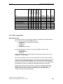
2.4 Specifying the properties of the control components
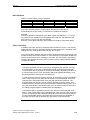
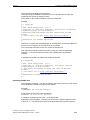
2.4.3 S5 Component
The S5 component may be backed up, loaded or compared.
A safety backup can also be made in the component.
The Properties dialog of the S5 component contains the following fields:
• Name:
Freely allocated name of the component.
• Remarks:
Freely editable field for user texts.
• Last comparison
Date and time of the last occasion when the online data was compared
with the offline data (for source data and memory dump).
• -load
Date and time of the last occasion when the offline data was transferred to
the S5 controller (for source data and memory dump).
• -backup
Date and time of the last occasion
© Siemens AG 2011 All Rights Reserved
SIMATIC A&D DataManagement Client - 07/2011
2-45
2 Operating A&D DataManagement
2.4 Specifying the properties of the control components
•
•
•
•
•
•
•
•
•
2-46
07/2011
Connection to the AG
The transmission mode is selected here. Via the SINEC H1 bus or via the
AS511.
Connection via H1
(Only activated if "Connection to the PLC" "H1" is selected.)
Device Name:
Default "/CP_H1_1:/SCP"
This setting defines the access point to the application. The setting is
independent of "Set PG/PC interface"; this enables access to S5 hardware
via H1 as well as to S7 hardware via MPI.
TSAP
(Transport Service Access Point) connection point between CP and CPU:
"S5_PGDIR" for a coupling via backplane bus, "S5PGCONN" for a
coupling via "monkey swing". (see CPxx manual)
Ethernet address
6 digit Ethernet address of the CP.
Notice: The Ethernet address must be unique, specified by a configuration
tool for S5 and loaded directly into the CP (launching the CP).
Link via the AS511
(Only activated if "Link to the AG" "AS511" is selected.)
COM interface
Interface selection for direct coupling of AG-PG/PC.
Password for the S5 CPU
If the S5 CPU is protected by a password, it can be entered here.
Notice: this option is not supported by all S5 CPUs.
Project path S5D file
Reference to the STEP5 project path under which the STEP5 project
(*.S5D) is stored.
© Siemens AG 2011 All Rights Reserved
SIMATIC A&D DataManagement Client - 07/2011
07/2011
2 Operating A&D DataManagement
2.4 Specifying the properties of the control components
•
•
•
•
•
S5 program button
Selects the path of the STEP5 project with a file browser. Acceptance is
possible by double clicking on the STEP5 project file.
Multibackup
This option enables the user to store up to 99 memory dumps of the
component. The number is specified in Max. no. of backups, also see
Subsection 2.4.1 and Subsection 2.6.2.
"OK" button
Transfers the entry and acknowledges the dialog positively.
Cancel button
Discards the entries and acknowledges the dialog negatively.
"Hel2 button
Help for the current entry fields.
2.4.4 S7 Component
All S7-300, S7-400 CPUs and the PC-based Win AC controls belong
to the S7-CPUs.
Because of the source data concept, the "S7-CPU" is only loaded and compared.
The "S7-CPU" is stopped before the transfer and then restarted afterwards.
However, there is an option of creating a backup of a "S7 CPU".
The Properties of the "S7 component" dialog enables the following settings to be
made:
• "Transfer AS configuration" option.
You transfer the hardwarecomponent, created with "HW config", to the
automationsystem (from the SDBs of the STEP7 project) with this option.
© Siemens AG 2011 All Rights Reserved
SIMATIC A&D DataManagement Client - 07/2011
2-47
2 Operating A&D DataManagement
2.4 Specifying the properties of the control components
•
•
•
•
•
•
07/2011
"Transfer AS link data" option.
If FDL links have been configured; these are also transferred when the S7
CPU is being loaded. This option can only be activated in V2 STEP7
projects. In V3 STEP7 projects, this information is transferred together with
the AS configuration (SDB).
The link data are also loaded with the transfer to the CP342-5 component.
"Start target module after editing" option.
You should always activate this option, so that ADDM automatically starts
the CPU after the transfer.
"RAM to ROM after transfer"option.
ADDM automatically stores the data here in the case of modules with
integrated FLASH.
With the setting "Routing via agent” the CPU will be contacted via an
installed ADDM Agent on an operator panel. For this function the name or
the TCP/IP address of the Agent computer has to be declared.
The "CPU Password” setting stores the password for access to passwordprotected CPUs.
The date and time are stored if the transfer is successful.
You create a reference to an S7 project with the "S7 program" button.
You store the S7 project itself in a directory (e.g. S7_projects) on the same
drive as the ADDM project.
Notice
A reference (pointer) to an S7 project must not be made from various ADDM
projects. Failure to observe this requirement may lead to loss of data in
connection with the Copy part projects and Archive functions.
2-48
© Siemens AG 2011 All Rights Reserved
SIMATIC A&D DataManagement Client - 07/2011
07/2011
2 Operating A&D DataManagement
2.4 Specifying the properties of the control components
Creating a reference to an S7 project
ADDM loads the data from a stated S7 project into the S7-CPU. A back transfer
into the S7 project is blocked to prevent the source data being inadvertently
overwritten.
ADDM requires a reference to the relevant S7 project in order to transfer the data.
1. To do this, select the S7 project in the Open dialog of the S7 browser.
2. Assign the storage path of the corresponding source project with the
"Browse” button.
3. The reference is stored in ADDM by selecting a ”Block” object in the righthand area of the display.
The browser is then closed automatically.
S7 source data
Source data maintenance is traced in S7 projects. This has the advantage that not
only the PLC programs are kept in the S7 projects but also the higher-level data for
the PLC. This includes, for example, variable tables and structures, connection
data between CPUs via MPI, PROFIBUS or Industrial Ethernet etc. Every CPU can
thus be accessed with a programming device, irrespective of the chosen
connection in a networked system. However, this requires source data
maintenance in the S7 project. The higher-level data is not stored on the CPU.
Back loading the CPU data into the project would lead to a loss of information.
Therefore it is impossible to back load into the S7 project with ADDM.
S7-backup
Nevertheless, in various applications, there is a need to back up the data contained
in the S7 CPU. This includes data generated by controller modules, or recipes
optimized by an operator during the work. It is possible to define an S7 backup so
that this data can be backed up despite the source data concept.
© Siemens AG 2011 All Rights Reserved
SIMATIC A&D DataManagement Client - 07/2011
2-49
2 Operating A&D DataManagement
2.4 Specifying the properties of the control components
07/2011
Note
If data is backed up in an S7 backup, ADDM reads back all program data of the
S7-CPU. Other fitted modules, such as CPs, must be backed up separately
Properties of the S7 backup
Clicking on the "S7 Backup” button in the properties of the S7 component opens
another properties window.
The specifications required for the S7 backup are made in this properties window.
As back loading the S7 data from the CPU into the source project (see S7 source
data) is not permitted in ADDM, ADDM creates a separate S7 project in the ADDM
structure. The S7 data are backed up in this project.
The date and time are stored in the case of a successful transfer or when a
comparison is made.
2-50
© Siemens AG 2011 All Rights Reserved
SIMATIC A&D DataManagement Client - 07/2011
07/2011
2 Operating A&D DataManagement
2.4 Specifying the properties of the control components
Note
With some CPUs, data or programs stored in the read only memory of the CPU
are also backed up. These blocks cannot be loaded back.
The following settings are offered:
•
Use the online address of the source project:
If there is a pointer to an S7 source project in the properties of the S7
component, ADDM uses the access addresses stored in the S7 source
project for online access to the S7 CPU.
•
Use the online address of the backup project:
If an S7 source project does not exist, then the access paths must be
defined in the backup project. This setting must be selected for this
purpose. The setting option is thus activated via the Online Address button.
Actuating the button opens Program Properties.
•
Multibackup:
This option enables the user to store up to 99 memory dumps of the
component, also see subsection 2.4.1 and subsection 2.6.2.
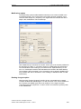
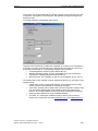
Properties Program (online) - local
The settings for online access are made in this window. The Local setting defines a
direct access to the S7-CPU via the MPI address. The address must be known to
the user. If this information is lacking, the address can be found in ADDM with the
Display Accessible Nodes function. The address is entered in the "Connection to
destination station" under address.
© Siemens AG 2011 All Rights Reserved
SIMATIC A&D DataManagement Client - 07/2011
2-51
2 Operating A&D DataManagement
2.4 Specifying the properties of the control components
07/2011
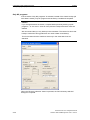
Properties Program (online) via network access
An online access via networks is achieved by selecting Accessible via Network
Transition. The following information is required for this purpose:
• As a rule, rack 0 and slot number 2 are the correct settings for the access.
• The MPI address of the CPU is stated under "Type”.
• The "Address” of the network node over which ADDM is to make the
access has to be entered. This may be an S7 CPU, a PROFIBUS CP or an
Ethernet CP. The S7 subnet ID must be stated as well as this address
information.
Note
These settings can only be made if the "Use Online Address of the Backup
Project” has been selected in the properties of the S7 back up component.
Caution
A faulty statement of addresses or S7 subnet ID may lead to accessing an
incorrect network node. This may destroy valuable data or cause damage to the
system when downloaded.
2-52
© Siemens AG 2011 All Rights Reserved
SIMATIC A&D DataManagement Client - 07/2011
07/2011
2 Operating A&D DataManagement
2.4 Specifying the properties of the control components
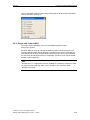
Query Subnet ID
In the "Accessible via Network Transition" procedure, access is made from a
higher-level network to a lower-level network (subnet). When configuring networks,
STEP7 automatically assigns a subnet identification, the S7 subnet ID, to
differentiate the networks. This information is essential for online access to network
nodes in the subnets. The information may be queried in the SIMATIC Manager via
the object properties of the network.
The above window is displayed by selecting the relevant network icon and
selecting the object properties. The S7 subnet ID shown there can now be entered
in the properties for the access via networks.
© Siemens AG 2011 All Rights Reserved
SIMATIC A&D DataManagement Client - 07/2011
2-53
2 Operating A&D DataManagement
2.4 Specifying the properties of the control components
07/2011
2.4.5 Communication modules CP342-5, CP343-1, CP443-1, CP443-5
CP data is edited and stored in S7 projects, so CPs can be loaded and
compared. ADDM therefore needs a reference to the corresponding S7 project
directory.
1. Click on the "S7 program" button and select the S7 project directory.
2. The reference to the CP communication module is not made to the S7
program but to the CP data.
ADDM transfers the data from the stated directory
Note
Always set the interface of the PG/PC in the Tools → Set PG/PC interface menu
item before the transfer to the component.
2-54
© Siemens AG 2011 All Rights Reserved
SIMATIC A&D DataManagement Client - 07/2011
07/2011
2 Operating A&D DataManagement
2.4 Specifying the properties of the control components
Properties of the CP342-5 backup
A CP342-5 can be backed up with the backup function. Clicking on the "Backup”
button opens the following Properties window:
The specifications required for the CP backup are made here. As back loading of
the CP data into the source project is not permitted in ADDM, ADDM creates a
separate S7 project in the ADDM structure. The CP data are backed up in this
project. The date and time are saved in the case of a successful transfer or a
comparison.
The following settings are available:
• Use online address of source project
If there is a pointer to an S7 source project in the properties of the CP
component, ADDM uses the access addresses stored in the S7 source
project for the online access to the S7-CPU.
•
Use online address of backup project
If there is no S7-source project, the access paths must be defined in the
backup project. This setting must be selected for that purpose. This
activates the setting option via the Online address button. Clicking on this
button opens Program Properties and enables the addresses to be
defined. The procedure and dialogs are the same as for backing up an S7
component.
•
Multibackup
This option enables the user to store up to 99 memory dumps of the
component, also see subsection 2.4.1 and subsection 2.6.2.
© Siemens AG 2011 All Rights Reserved
SIMATIC A&D DataManagement Client - 07/2011
2-55
2 Operating A&D DataManagement
2.4 Specifying the properties of the control components
07/2011
CP342-5 in V2 STEP7-project
STEP7 projects Version V2 store the data of a CP in the hardware data of the
CPU. Therefore create a reference to the S7-CPU.
ADDM opens the HW config tool under STEP7 to load V2 STEP7 projects into the
CP. Select the corresponding CP from the table in this tool and start the loading
procedure. Only at this point, the SDBs, which are already available in a V3 STEP7
project, are generated. Therefore, the loading process must be triggered out of HW
Config.
ADDM automatically detects whether it is a V2 or V3 STEP7 project.
If so-called FDL links are set up in addition to normal master-slave data, then
ADDM also transfers them when loading the CP.
Note
This data is also transferred when loading the S7-CPU if the "Transfer AS link
data” option is selected.
2.4.6 OP, TP and MP operator panels with ProSave
In ADDM, operator panels can be backed up, loaded and compared via ProSave
software. ProSave is also installed during the installation of ADDM.
2-56
© Siemens AG 2011 All Rights Reserved
SIMATIC A&D DataManagement Client - 07/2011
07/2011
2 Operating A&D DataManagement
2.4 Specifying the properties of the control components
The function can be activated with the "Backup” button in the Properties of the OP
Component. If the button is coloured grey, the selected OP does not support the
backup function.
On clicking "Backup” the following dialog opens:
The data can be backed up, loaded and compared. In so doing, it must be borne in
mind that, of course, only that data can be transferred back to the OP, which had
previously been backed up. The following transfers can be defined:
• "Complete backup” backs up all the data of the OP.
• With the "Recipes” setting, only the recipe data of the OP is backed up.
• "Passwords” enables passwords to be backed up.
• With some OPs, the "Firmware” of the OP can be backed up (e.g. OP 17).
The specification in the "Transfer channel” determines the type of connection to the
operator panel
• "Serial” links the OP via the serial interface. The COM port and the data
transfer rate must be specified for the backup computer.
• Some OPs, primarily the PC-based OPs, have an "Ethernet” interface. This
may be used for data transfer. Select Ethernet if the OP supports this
function. The TCP/IP address of the OP must be entered for this purpose.
• Enter the "MPI” address for a link via MPI/PROFIBUS.
• The "Max. no. of backups” enables the user to store up to 99 memory
dumps of the component, see also subsection 2.4.1 and subsection 2.6.2.
© Siemens AG 2011 All Rights Reserved
SIMATIC A&D DataManagement Client - 07/2011
2-57
2 Operating A&D DataManagement
2.4 Specifying the properties of the control components
07/2011
Possible connections from all OPs
Seriell 9600
Seriell 19200
Seriell 38400
Seriell 57600
Seriell 115200
In this table all possible connections and there necessary settings are listed:
1
1
0
1
1
0
0
0
0
1
0
0
0
1
1
0
1
1
1
1
1
1
1
1
1
1
1
1
1
1
1
1
1
1
1
1
1
0
0
1
0
1
1
0
1
1
1
1
1
1
0
1
1
0
1
1
1
1
1
1
1
1
1
1
1
1
1
1
1
1
1
1
1
1
1
1
0
1
0
1
1
0
1
1
1
1
1
1
0
1
1
0
1
1
1
1
1
1
1
1
1
1
1
1
1
1
1
1
1
1
1
1
1
1
0
0
0
0
0
0
1
1
1
1
1
1
0
0
0
0
1
1
1
1
1
1
1
1
1
1
1
1
1
1
1
1
1
1
1
1
1
1
0
0
0
0
0
0
0
0
0
0
0
0
0
0
0
0
1
1
1
1
1
1
1
1
1
1
1
1
1
1
1
1
1
1
1
1
1
1
OP
OP3
OP7
OP15
OP17
TD17
OP25
TP27-6
TP27-10
OP27
OP35
OP37
TP37
C7-626
C7-633
C7-634
new:
TP070
TP170A
TP170 MICRO
TP170B MONO
TP170B COLOR
OP170B
Mobile Panel 170
C7-635 OP MONO
C7-635 TP B MONO
TP270 6"
TP270 10"
OP270 6"
OP270 10"
MP270B
MP270
MP270B 6"" TOUCH
MP270B TOUCH
MP370
MP370 TOUCH
MP370 15" TOUCH
OP77B
OP 73
2-58
Ethernet
MPI
0
0
0
0
0
0
0
0
0
0
0
0
0
0
0
0
0
0
0
1
1
1
0
1
1
1
1
1
1
1
1
1
1
1
1
1
0
0
USB
1
0
0
0
0
0
0
0
0
1
0
0
0
0
0
0
0
1
0
1
1
1
1
1
1
1
1
1
1
1
1
1
1
1
1
1
1
1
0
0
0
0
0
0
0
0
0
0
0
0
0
0
0
0
0
0
0
0
0
0
0
0
0
1
1
1
1
1
1
1
1
1
1
1
1
0
© Siemens AG 2011 All Rights Reserved
SIMATIC A&D DataManagement Client - 07/2011
Seriell 19200
Seriell 38400
Seriell 57600
Seriell 115200
2 Operating A&D DataManagement
2.4 Specifying the properties of the control components
Seriell 9600
07/2011
0
0
0
0
0
0
0
0
0
1
1
1
1
1
1
1
1
1
1
1
1
1
1
1
1
1
1
1
1
1
1
1
1
1
1
1
1
1
1
1
0
0
0
0
0
OP
OP 73 micro
OP 77A
TP 177A 6"
TP 177 micro
TP 177B mono DP
TP 177B color PN/DP
OP 177B mono DP
OP 177B color PN/DP
Mobile Panel 177 DP
Ethernet
MPI
0
0
0
0
0
1
0
1
0
USB
0
1
1
0
1
1
1
1
1
0
0
0
0
1
1
1
1
0
Please refer to ProSave for transmission options for other devices.
2.4.7 Drive component
Selecting the drive
The following drives can be managed, backed up, loaded and compared with the
drive component under A&D DataManagement.
• SIMODRIVE 611Universal, 611Universal e
• POSMO CA
• POSMO CD
• POSMO SI
• POSMO A 75W, 300W.
Provided that Drive ES version 5.3 or above is installed, drives from the
• Combimaster
• MASTERDRIVES
• SIMOREG
families can be managed, saved, loaded and compared, as long as they can be
integrated in a Step7 project.
As well as the backed up data, the drive component can contain safety backups.
These drives have their own closed-loop computer and work in conjunction with S7
controls or with the SINUMERIK 840Di. The control system and drive generally
exchange their data over the PROFIBUS DP. Certain versions of the SIMODRIVE
611Universal can also be controlled as a stand-alone device via terminals.
Selecting the motor symbol or the Insert → Drive menu displays the following
selection list of the drive component. A double click on the desired drive, and
ADDM inserts the drive into the list. Double clicking on the inserted drive
component opens the properties dialog.
© Siemens AG 2011 All Rights Reserved
SIMATIC A&D DataManagement Client - 07/2011
2-59
2 Operating A&D DataManagement
2.4 Specifying the properties of the control components
07/2011
Before a data transfer will be started, the drive type is checked by ADDM. If a
difference is found, the transmission will be aborted by ADDM with an error
message.
From the ADDM version 5.2 the drive type check is done as well, but now the user
may decide if the transfer should be aborted or not. So in a configured 611U type
it"s possible to backup the data of a real 611UE type.
Drive interfaces
The coupling to the drive for the data backup with ADDM may take place over
various interfaces depending upon the drive or drive variant used. The matching
transfer cable is then required for this purpose. The following interfaces are
available for data exchange.
• RS-232, serial
• PROFIBUS DP
SimoComU/A
The software packages SimoComU/A are available for starting up the drives.
These software packages are needed for processing the drive components with
ADDM on the backup computer. SimoComU/A are supplied on the installation CD.
The SimoComU/A software provides their own user interface for starting up and
maintaining the drives. ADDM uses the up and download functions of the
SimoComU/A software in the background. This means that the SimoComU/A
interface remains invisible while operating with ADDM. However, all the backed up
drive data can be processed and of course changed with SimoComU/A..
Caution
The SimoComU/A software may be installed in different versions on the same
computer. For using in correlation with ADDM, only the actual version of
SimoComU/A should be installed once. Older versions must be removed from the
computer before using ADDM.
2-60
© Siemens AG 2011 All Rights Reserved
SIMATIC A&D DataManagement Client - 07/2011
07/2011
2 Operating A&D DataManagement
2.4 Specifying the properties of the control components
DriveES
The DriveES software package is provided for starting up the drives in the
Combimaster, MASTERDRIVES and SIMOREG families. The software package is
required for processing drive components with ADDM on the backup computer.
DriveES is not supplied on the installation CD. The DriveES software provides its
own user interface for starting up and maintaining the drives. ADDM uses the up
and download functions of the DriveES software in the background. This means
that the DriveES user interface remains hidden while operating with ADDM.
However, all the backed up drive data can be processed and of course changed
with DriveES..
Properties of a SIMOCOM U/A drive
The Properties dialog of the drive component contains the following fields:
• Last comparison
Date and time of the last occasion when the online data was compared
with the offline data.
• -load
Date and time of the last occasion when the offline data was transferred
into the drive.
• -back up
Date and time of the last occasion when the drive data was backed up.
© Siemens AG 2011 All Rights Reserved
SIMATIC A&D DataManagement Client - 07/2011
2-61
2 Operating A&D DataManagement
2.4 Specifying the properties of the control components
•
•
•
•
•
•
2-62
07/2011
Drive A – Drive B
The Simodrive 611 Universal drive can be supplied with either one or two
axes on a module. On modules with two axes, these axes are
distinguished by being named drive A and drive B. This can be set in
ADDM.
Routing via agent
With this setting the drive is connectable via a network computer with
ADDM-Agent. For this the name or the TCP/IP address of the computer
has to be declared.
RS-232 / RS-485
The 611U and 611UE drives are loaded, compared and backed up via the
RS-232 / RS-485. The COM1/2 interface of the backup computer has to be
set. The transfer may also be made over the PROFIBUS with an optional
expansion module.
PROFIBUS
When the PROFIBUS is used as a transmission route, the coupling to the
drive may be made in various ways.
If the backup computer is connected directly to the PROFIBUS segment of
the drives (direct connection), the PROFIBUS address set for the drive
must be stated in order to gain access.
If the backup computer is connected via a SIMATIC S7 or a higher-level
PROFIBUS segment (routed via S7 CPU), the subnet ID of the network
segment and the MPI address of the S7 CPU must be stated. In the
STEP7 project, the subnet ID information can be queried via the SIMATIC
Manager.
Multi-backup
This option enables the user to store up to 99 memory dumps of the
component. The number is specified in Max. no. of backups, also see
subsection 2.4.1 and subsection 2.6.2.
Parameter file
In ADDM, the button for selecting the parameter file sets a pointer to the
drive start up data. Actuating the button opens a browser for navigating to
the drive data. The data is generated and stored with the SimoComU/A
software package.
© Siemens AG 2011 All Rights Reserved
SIMATIC A&D DataManagement Client - 07/2011
07/2011
2 Operating A&D DataManagement
2.4 Specifying the properties of the control components
•
File information
Information about the parameter file can be called with this button. This
serves for linking the correct drive file.Datei-Info.
Properties of a DriveES drive
The Properties dialog of the DriveES drive component contains the following fields:
• Last comparison
Date and time of the last occasion when the online data was compared
with the offline data.
• -load
Date and time of the last occasion when the offline data was transferred
into the drive.
• -backup
Date and time of the last occasion when the drive data was backed up.
• File
Reference to the physical project path for the parameter file on the storage
medium.
© Siemens AG 2011 All Rights Reserved
SIMATIC A&D DataManagement Client - 07/2011
2-63
2 Operating A&D DataManagement
2.4 Specifying the properties of the control components
2-64
07/2011
•
S7 progr. path
Reference to the STEP7 project path under which the STEP7 project is
stored along with the DriveES drive that was configured there.
•
Max. no of
The maximum permissible number of backups is specified here.
•
S7 project path
DriveES manages the drives connection data in a Step7 project. To
transfer the data, therefore, ADDM requires a reference to the
corresponding S7 project.
•
Select the S7 project in the S7 browser"s Open dialog.
•
Using the "Browse…” button, assign the storage path of the corresponding
source project.
•
The reference is saved in ADDM by selecting a parameter set in the righthand display area.
The browser then closes automatically.
•
Delete path
Deletes the S7 project path.
© Siemens AG 2011 All Rights Reserved
SIMATIC A&D DataManagement Client - 07/2011
07/2011
2 Operating A&D DataManagement
2.4 Specifying the properties of the control components
2.4.8 HMI DOS OP 031 operator panel
The HMI DOS operator panel OP 031 is loaded via Interlink.
Switch the operator panel into transfer mode before the transfer. To do this, the OP
is explicitly configured, or you branch into the Load menu with power ON and key
<6>.
See the OP 031 operator manual for more details.
The data is packed after you have acknowledged the query, and the MMC goes
into server mode
Select the Type of operator panel to be configured. ADDM supports the following
types:
• S7
• MCU
• NCU
• Hüller Hille NC
ADDM enables operator panel texts, configurations and HiGraph diagnostic data to
be stored
• in the plant structure
• in any directory on the same drive.
In order to find the texts in any directory on the same drive again, create a
reference to it with the aid of the HMI path button. ADDM then transfers the
operator panel texts from the stated directory.
Note
The operator panel texts must be stored according to the defined directory
structure of the DOS package. Only in this way can ADDM find the user texts,
configurations and diagnostics data, and load them onto the operator panel.
© Siemens AG 2011 All Rights Reserved
SIMATIC A&D DataManagement Client - 07/2011
2-65
2 Operating A&D DataManagement
2.4 Specifying the properties of the control components
07/2011
2.4.9 Serial component
Devices with a RS-232 interface can also be backed up with ADDM.
The prerequisites for this are that:
• The data is transferred without a protocol
• The data are stored in a file.
The serial component can be loaded and backed up.
You open the "Interface parameters” dialog with the "Parameter...” button.
You define the settings for the "Serial interface” in the "Interface parameters”
dialog.
Set the maximum permissible transfer time in the "Timeout (s)” field.
Notice
Make absolutely sure that the Timeout value is set correctly.
2-66
© Siemens AG 2011 All Rights Reserved
SIMATIC A&D DataManagement Client - 07/2011
07/2011
2 Operating A&D DataManagement
2.4 Specifying the properties of the control components
You change into the parameter text display with the "Edit” button.
Here, you enter details of the relevant interface.
ADDM stores the settings of the serial interface in a file, for example in "Serial.cfg”.
You can still change all the parameters directly before the data transfer.
If the serial interface does not output an EOF (end of file) during the backup, then
ADDM ends the transfer after this time and saves the data.
© Siemens AG 2011 All Rights Reserved
SIMATIC A&D DataManagement Client - 07/2011
2-67
2 Operating A&D DataManagement
2.4 Specifying the properties of the control components
07/2011
2.4.10 Path component
The path component enables any directory tree to be backed up, loaded and
compared via ADDM. The only condition is that the source and target drives are
linked with the ADDM computer.
•
•
•
•
2-68
Assign a "name” (max. of 32 characters) to the zip archive to be backed
up.
Describe the contents to be backed up in more detail in the "Remarks”
field.
In the area "Backup path/file” the share a pc name can be given in
manually (UNC path). With this UNC path a logical drive connection is not
any more necessary. The access to the defined pc or path is sometimes
only for certain users allowed in the network. In this case an allowed user
can be assigned.
With "Back up single file", a single file can be backed up in a directory.
The path desired for the loading procedure is stored in ADDM with the Use
backup path when loading option. Without this option, you must navigate to
the desired target directory when loading.
© Siemens AG 2011 All Rights Reserved
SIMATIC A&D DataManagement Client - 07/2011
07/2011
2 Operating A&D DataManagement
2.4 Specifying the properties of the control components
•
•
The "Multi-backup” option enables the user to store up to 99 memory
dumps of the component.
The "Permit NC files on PCU” option allows a user with the Maintain NC
files right to perform the NC files function on the PCU with this component.
The "Find…" button selects the browser for navigation.
All drives are offered for defining the backup path, including the linked network
drives. After the drive or directory has been selected, the path is stored with the
"OK” button.
Notice
If the stored path lies on a network drive linked to the backup computer, it must
be ensured that this network drive is also linked to the backup computer during
the loading procedure.
Assign user
The button "Assign user...” opens the following dialog. There the allowed user will
be assigned with his password. So that a not authorized user may backup or load
the defined file or path.
© Siemens AG 2011 All Rights Reserved
SIMATIC A&D DataManagement Client - 07/2011
2-69
2 Operating A&D DataManagement
2.4 Specifying the properties of the control components
07/2011
If the backup computer is linked to a network, the backup path may also lie in a
network computer. ADDM displays all accessible network computers for selection
in the browser. Access to the current computer must however be permissible for
the user on the backup computer. That"s not needed if an authorized user is
assigned by the button "Assign user...”.
Backup
You backup a path component with the Transfer → Hardware to PC (backup)
menu.
Select the directory to be backed up in the "Backup the path component” dialog.
The original path and all files and directories lying under it are packed in a *.zip
archive file, and stored in the ADDM project directory.
Load
You load a path component with the Transfer → PC to hardware (load) menu.
Select the target directory for restoring the backed up files in the "Load the path
component” dialog. The archive file is unpacked in this directory.
2-70
© Siemens AG 2011 All Rights Reserved
SIMATIC A&D DataManagement Client - 07/2011
07/2011
2 Operating A&D DataManagement
2.4 Specifying the properties of the control components
2.4.11 PCIN component
The PCIN is a component, which is embedded in ADDM, it can also be addressed
serially. This component uses special protocols so that the "serial component"
cannot be used for data transfer.
With the PCIN component, the following products can be supplied with their data:
• PC box MMC100 without hard disk
• PC box MMC100.2 without hard disk
• Operator panel OP 030
• Hand-held programming unit HPU
• Hand-held terminal HT 6
Properties of the PCIN component
Double clicking on the installed PCIN component opens the properties dialog.
•
•
•
•
Enter the name of the component in the "Name” input field (max. of 32
characters).
Additional notes about the component may be entered in the "Remarks”.
The PCIN component can be loaded and backed up.
The control panels of the PCIN component can be supplied with various
data. The software version may be updated via a "config.bin” file, or user
texts or images may be loaded on the control panel. The user texts or
images are provided by the machine manufacturer.
© Siemens AG 2011 All Rights Reserved
SIMATIC A&D DataManagement Client - 07/2011
2-71
2 Operating A&D DataManagement
2.4 Specifying the properties of the control components
•
07/2011
Because of the various possibilities of data provision, ADDM offers the
user a simple choice of loading options via the "Data type”. Only a single
file, a complete directory, or several files from a file list may be transferred.
Select data
The data is selected with the "data pointer”.
The dialog is opened with the "Find” button.
The file browser is used for the selection. The OK button transfers the data into the
data pointer and closes the dialog
Creating a file list
A file list can be simply created with the File list button. Pressing the "File list”
button opens the "File selection dialog”.
2-72
© Siemens AG 2011 All Rights Reserved
SIMATIC A&D DataManagement Client - 07/2011
07/2011
2 Operating A&D DataManagement
2.4 Specifying the properties of the control components
The list of files is created with the "Add” button. This opens the same file browser
described under "Select file”. The file is selected in the same way. Pressing the OK
button transfers the file into the list. ADDM closes the dialog and stores the list in
the list window.
List elements can be deleted from the file list by selecting them and then pressing
"Delete”.
Setting COM parameters
Selecting the Setting button in the COM parameter area enables the transfer
parameters to be set.
The parameters have to be set according to the settings of the current target
device. Ensure that the settings in ADDM are the same as the settings in the target
device.
Notice
If ADDM and the target device are set differently, there will be a data transfer
error as the data transfer cannot run properly.
© Siemens AG 2011 All Rights Reserved
SIMATIC A&D DataManagement Client - 07/2011
2-73
2 Operating A&D DataManagement
2.4 Specifying the properties of the control components
07/2011
Coupling to the backup computer
The PCIN component is linked to the backup computer by a standard serial cable.
The cable is connected to the COM1 or COM2 port of the backup computer and to
the serial interface of the HPU. The MMC 100 or MMC 100.2 components are
standard PCs without hard disks but with a COM port.
Fig. 2-1: Projektierungsdaten auf portable Medien kopieren
Necessary settings for HPU
For transferring the system software to the HPU, the following settings are
necessary:
XON = 11
XOFF = 13
Parity = EVEN
Baud rate: 9600 - 57600 BAUD
Additionally, a file list with the following structure must be created:
sys_code.bin
sysfile.bin
projdata.bin
projtext.bin
alarmtext.bin
config.bin
All files should be taken from the directory HPU_DVK/FLASHBIN. For transferring
parts of the system software, the following files in the list shown must be also
transferred.
If only alarm texts have to be transferred, the list is as follows:
alarmtext.bin
config.bin
Necessary settings for MMC 100.2
For transferring the system software to the MMC 100.2, the following settings are
necessary:
XON = 11
XOFF = 13
Parity = NONE
Baud rate: 19200 BAUD
2-74
© Siemens AG 2011 All Rights Reserved
SIMATIC A&D DataManagement Client - 07/2011
07/2011
2 Operating A&D DataManagement
2.4 Specifying the properties of the control components
Additionally, a file list with the following structure must be created
(C:\temp\sys)
sys_0000.bin
sys_0001.***
.
sys_00XY.***
*** :
.bin or .exe
XY :
57 for system data
45 for application data
The end numbers 57 or 45 are valid for tested software version 5.3.12 from the
MMC 100.2.
The files should be taken from the directory "mmc100pj.sys\temp” resp.
"mmc100pj.app\temp”. First the system data should be transferred and then the
application data. If the system data are already loaded, modified application data
may also be transferred
Procedure for creating a file list
On the disk drive, where the ADDM project data is located, a directory (e.g.
C:\temp\sys) has to be created. Out of the system- or application directory (e.g.
A:\mmc100pj.sys\temp) the files must be transferred into the created directory.
With the function "ADD" (file selection list) the files must be added separately into
the file selection list.
© Siemens AG 2011 All Rights Reserved
SIMATIC A&D DataManagement Client - 07/2011
2-75
2 Operating A&D DataManagement
2.4 Specifying the properties of the control components
07/2011
2.4.12 Neutral component
The neutral component offers the possibility to adapt foreign applications to ADDM
by an easy way. The application must have a command interface or allows to be
controlled via batch files.
Properties dialog box of the neutral component
The neutral component is used to "remotely control" applications with ADDM that
do not have an interface to ADDM. In this case, the application must able to be
called via the command lines or to be controlled using batch files.
The parameters of the neutral components are individually listed below:
• Name:
Freely assignment component name.
2-76
•
Remarks:
Field for user texts that can be freely edited.
•
Last comparison
Date and time of the last comparison between online data and source data.
© Siemens AG 2011 All Rights Reserved
SIMATIC A&D DataManagement Client - 07/2011
07/2011
2 Operating A&D DataManagement
2.4 Specifying the properties of the control components
•
-load
Date and time that offline data was last loaded into the target system.
•
-backup
Date and time that online data was last transferred from the target system
into the backup PC.
•
Load command
This button opens a dialog box in which a command line can be entered to
load or to call a batch file to download the data into the hardware.
•
Backup command
This button opens a dialog box in which a command line can be entered to
backup or to call a batch file to save data in the backup PC.
•
Compare command
This button opens a dialog box in which a command line can be entered to
compare or to call a batch file to compare online data with offline data. In
this case, a comparison is made in the called third-party application. The
result of the comparison is either transferred to ADDM via a return file or,
after a successful comparison, the user must click on the comparison
result in a dialog box.
•
Checkbox "Make comparison in ADDM"
When this checkbox is activated, the comparison run is not carried-out in a
third-party application, but instead, in ADDM.
•
Compare command
This button can only be used if the checkbox "Make comparison in ADDM"
is activated. This button opens a dialog box in which a command line can
be entered to temporarily save online data or to call a batch file to
temporarily upload online data. In order that ADDM finds this data to make
a comparison, the space retainer %TEMPPATH% must be specified in the
upload target path.
•
"Binary comparison" option button
This option button specifies as to whether the temporarily saved data
should be compared in the binary format. As a comparison result, an
overview with all files is opened that indicates any differences.
•
"ASCII comparison" option button
This option button specifies whether the temporarily saved data should be
compared in the ASCII format. As a comparison result, an overview with all
files is opened that indicates any differences. The appropriate file can be
opened by double clicking on it and the differences are highlighted in color.
© Siemens AG 2011 All Rights Reserved
SIMATIC A&D DataManagement Client - 07/2011
2-77
2 Operating A&D DataManagement
2.4 Specifying the properties of the control components
•
07/2011
Name of the return file
Name of the return file which is used to return the value from the called
application to ADDM. The contents of the return file describe the result of
the action as follows:
[Returncode]#error textwhereby the gate symbol (#) is used as separator.
The value [Returncode] can assume the following values:
<0:
Error code of the application.
=0:
The action was successfully completed.
=1:
The action was successfully completed and there were no
differences.
=2:
The comparison was successfully completed and there were differences.
=3:
Undefined state.
If this field is empty, then after the action has been completed, ADDM
opens a dialog box in which the user must define the comparison result.
•
Timeout:
Time in seconds until the action is interrupted.
•
Max. no. of backups:
Defines the maximum number for the memory dumps. If this number has
been reached, the next time that a memory dump is created, the oldest
memory dump is overwritten.
•
Checkbox: Routed via Agent
By activating this option, the command line of the neutral component is not
executed at the ADDM computer but is routed via "Agent" computer. The
"Agent" computer is defined in the appropriate field by entering the IP
address or the computer name.
Load command
On clicking the button "Load command” the appropriate dialog will be opened.
The command can be defined in the input area. If a command is defined, no direct
disk drive name should be given in within the command line. Another ADDM-Client
(computer) may have a different drive indication for the same drive.
In this case the function is not working, because the drive name will be not found.
2-78
© Siemens AG 2011 All Rights Reserved
SIMATIC A&D DataManagement Client - 07/2011
07/2011
2 Operating A&D DataManagement
2.4 Specifying the properties of the control components
With the button "Find…” a browser opens and allow you to navigate into directories
and select files with commands for execution.
A selection of a file will close the browser dialog and the information is stored in the
command window.
Backup command
The button Backup command opens the dialog for defining the command for
backup.
© Siemens AG 2011 All Rights Reserved
SIMATIC A&D DataManagement Client - 07/2011
2-79
2 Operating A&D DataManagement
2.4 Specifying the properties of the control components
07/2011
In the same way as at the Command load a browser can be opened with the button
"Find...”.
A selection of a file will close the browser dialog and the information is stored in the
command window.
Compare command
The button "Compare command" allows the definition of the command compare. In
this case the application, which is called via the command, have to do the
comparison independent.
2-80
© Siemens AG 2011 All Rights Reserved
SIMATIC A&D DataManagement Client - 07/2011
07/2011
2 Operating A&D DataManagement
2.4 Specifying the properties of the control components
The button "Find..." opens the file browser as well.
A selection of a file will close the browser dialog and the information is stored in the
command window.
Comparison executed by ADDM
If the application has no possibility of comparison, ADDM can carry out the
compare. For that the flag comparison executed by ADDM have to be set.
With the button "Compare command" the command dialog will be opened.
© Siemens AG 2011 All Rights Reserved
SIMATIC A&D DataManagement Client - 07/2011
2-81
2 Operating A&D DataManagement
2.4 Specifying the properties of the control components
07/2011
In the same way as at the other commands a browser can be opened with the
button "Find....”.
A selection of a file will close the browser dialog and the information is stored in the
command window.
Comparing binary or ASCII
With the selection "Compare binary" or "Compare ASCII" in ADDM will be defined
in which way the comparison should be done.
On comparing binary data ADDM takes the data as an executable program code.
On selection comparing ASCII ADDM compares the data as a text (characters).
This data also ca be displayed in ADDM.
Returnfile
Here will be defined the name of the Returnfile. Via this file the called application
sends return values to ADDM. The content of the Returnfile describes the results of
the execution as follows:
[Returncode]#Errortext
The sign number (#) is in this case a sign for separation.
The returncode may have following values:
<0:
Errorcode of the application.
=0:
The execution was succeeded.
=1:
The comparison was succeeded and no differences were found.
=2:
The comparison was succeeded and differences were found.
=3:
Undefined state.
If there is no information after the execution, ADDM opens a dialog box in which
the user has to decide how the result of the comparison was.
2-82
© Siemens AG 2011 All Rights Reserved
SIMATIC A&D DataManagement Client - 07/2011
07/2011
2 Operating A&D DataManagement
2.4 Specifying the properties of the control components
The "Timeout” defines the time in seconds after the execution will be aborted.
The "Max. no. of backups” defines the max. number of backups, which should be
done by ADDM. If the max number of backups is reached, ADDM overwrites the
oldest backup at the next executed backup.
Routing neutral components
The special feature when routing neutral component is that the absolute paths in
the command line must refer to the hard disk of the Agent component. The only
exception to this rule is the path to the batch file.
An example:
The command line to save neutral components is as follows:
"D:\Batches\Upload.bat"
"D:\Verzeichnis1\Verzeichnis2\*.*" "%DATAPATH%"
"%COMPPATH%Returnfile.txt"
The associated batch file "Upload.bat" copies everything from the directory
"D:\folder1\folder2" into the target directory of the neutral component represented
by the space retainer "%Datapath%". This means the path of the source data or
the appropriate backup path. The third parameter defines that the result of the copy
in a return file with the name "Returnfile.txt" should be entered in the component
path.
The backup task is executed as follows:
•
•
•
•
•
•
•
After establishing contact to the Agent computer, the batch file is copied to
the Agent computer in the directory "C:\Neutralbatch".
The space retainers "%Datapath%" and "%COMPPATH%" are replaced by
"C:\Neutraldata".
After this, the batch file is run on "C:\Neutralbatch".
The files from "D:\folder1\folder2" on the Agent computer are copied into
the directory "C:\Neutraldata" and then the result of the copy operation is
written into the file "C:\Neutraldata\Returnfile.txt".
The ADDM Client now retrieves all files – with the exception of the file
"Returnfile.txt" - onto the ADDM Client computer and copies them into the
data directory or the backup directory of the components.
Finally, the Agent computer downloads the file "Returnfile.txt" onto the
ADDM Client computer and saves it in the component directory where it is
evaluated.
Before completing the backup operation, directories "C:\Neutraldata" and
„C:\Neutralbatch" on the Agent computer are deleted.
Information on "Routing via Agent"
When routing, the required data are first copied to the Agent computer. To do
this, two directories are set-up on the Agent computer:
C:\Neutralbatch for batch files
C:\Neutraldata for net (useful) data and for the return file
This means that the space retainer "%DATAPATH%" must always be specified
as source for net (useful) data. The reason for this is that this space retainer is
replaced by "C:\Neutraldata" on the Agent computer.
© Siemens AG 2011 All Rights Reserved
SIMATIC A&D DataManagement Client - 07/2011
2-83
2 Operating A&D DataManagement
2.4 Specifying the properties of the control components
07/2011
Example of a batch:
Rem %1
Rem %2
Rem %3
Xcopy /E %1 %2
Echo 0#Dingdong>%3
2.4.13 SINUMERIK components
The SINUMERIK component is saved (backed-up) and loaded from HMI →
Services via the ARCHIVE function. The comparison with the HMI archive is
realized offline with a temporarily generated ADDM archive.
Note
To ensure that the backup or loading process runs smoothly, an HMI Advanced
must be started on that computer which is connected with the NCU.
2-84
© Siemens AG 2011 All Rights Reserved
SIMATIC A&D DataManagement Client - 07/2011
07/2011
2 Operating A&D DataManagement
2.4 Specifying the properties of the control components
The "Properties of the SINUMERIK component" dialog box contains the
following information:
•
•
•
•
•
Name:
Freely assignable component name (max.32 characters).
Remarks:
Field for user texts that can be freely edited.
Last comparison
Date and time that online data were last compared with offline data.
-load
Date and time that data were last downloaded into the component.
-backup
Date and time that NCU data were last backed-up.
Addressing
The NCU or PLC are addressed via the parameters set in HMI Advanced.
Caution
If, while a SINUMERIK is operational, data is changed either from the
SINUMERIK itself or from the operator.
In this case, a backup already started via ADDM may be ended with errors. The
reason for this is that the ADDM cannot access data. If a communications error
occurs, the backup must be unconditionally repeated otherwise the modified data
cannot be backed-up.
In order to backup (archive), load or compare an NCU, all channels must be in
the RESET state. If this is not the case, then this can result in inconsistent data. If
all of the channels are in the RESET state, then start with the backup operation.
The progress dialog box showing the NC backup operation is always shown. This
means that every operator can see that presently a backup is being made. If not
all of the channels are in the RESET state, then an error message is returned to
the calling ADDM Client and displayed.
If the backup task is controlled by the job, then the job is interrupted with error
state -2. This means that the job is repeated after a pre-set time. If the maximum
number of repeats has been reached and the NCU has still not been backed-up,
the job is terminated and the next time that it will be executed is calculated. In this
case, the NCU was not backed-up in the backup cycle that expired.
M:N
For M:N configurations, the "M:N controller” checkbox must be activated. This
defines which controls are to be accessed and the "Name of the controller” must
be entered in the appropriate input field.
© Siemens AG 2011 All Rights Reserved
SIMATIC A&D DataManagement Client - 07/2011
2-85
2 Operating A&D DataManagement
2.4 Specifying the properties of the control components
07/2011
Contents of the backup
Checkboxes NCU, loadable compile cycles, PLC and PROFIBUS drives are
used to define which components should be the contents of the backup of the
SINUMERIK components. Every component can be backed-up independently
of the others. A dedicated archive file is generated for each component of the
backup.
If the NC does not contain any compile cycles or drive data, but the appropriate
selection was made, the following applies:
• An alarm is only output to indicate that this component was not able to
be backed up if at least one additional component was successfully
backed up.
• If a partial backup is not possible, because e.g. only compile cycles are
selected, then the backup is exited with error.
• If an error other than "Data do not exist” occurs, then the backup is
always exited with an error.
Notice
If the M:N option is activated:
• The backup options "Loadable compile cycles” and "PROFIBUS drives"
are grayed out.
• If, during the backup, ADDM detects that the NC is an 840D sl, backup is
interrupted and an error message is output.
Option, Routing via agent
SINUMERIK can also be addressed via a computer with ADDM Agent in the
network using Routing via agent. To do this, the computer name or the TCP/IP
address of the Agent computer should be specified via which this component is
connected.
Notice
For "Routing via agent”, HMI Advanced is expected on the PCU 50!
Save only in the reset state
Caution
We recommend that data is only backed-up in the reset state. The reason for this
is that backups carried-out during production can result in data inconsistency!
This is the reason that the backup checkbox "Save only in the reset state" is set
as standard.
Max. no. of backups
The number of backups to be saved from ADDM is defined in the input field
"Max. no. of backups”. When saving, ADDM takes into account what has been
specified and saves a new backup separately. If the "Max. no. of backups” is
reached, data is saved in the oldest backup. This data is then overwritten. This
means up to a maximum of 99 backups can be backed-up in ADDM , also refer
to chapter 2.5.2.
2-86
© Siemens AG 2011 All Rights Reserved
SIMATIC A&D DataManagement Client - 07/2011
07/2011
2 Operating A&D DataManagement
2.5 HD component
2.5 HD component
You backup complete hard disk contents in compressed image files with the HD
component. These are stored on the ADDM computer in the directory of the HD
component (Backup). On loading the image files are also transferred back to
hard disk of the destination computer (Restore).
The software supplied with ADDM also includes Symantec Ghost V 8.2 (inc.
Ghost Explorer). The documentation for all Ghost tools is supplied with ADDM.
2.5.1 HD Component via network for MS DOS
HD component via network
The "computer to be backed up” (e.g. MMC) is networked with the ADDM
computer under MS DOS.
Fig. 2-2: HD component via network
You can load the network driver for MS DOS required to do this in three ways:
• from a boot disk
• from a bootable CD-ROM
• from a bootable USB flash drive
• locally from a hard disk
© Siemens AG 2011 All Rights Reserved
SIMATIC A&D DataManagement Client - 07/2011
2-87
2 Operating A&D DataManagement
2.5 HD component
07/2011
Properties of the HD component
Backing up or loading an HD component via the network consists of several
indexing steps.
In this section all of the indexing steps are described in detail.
Connecting the computers
If the two computers are not already connected in a shared network (workgroup or
domain), the computers are connected as follows:
• Without hub via a direct twisted pair cable.
• With hub via two patch cables
1. Then, under Start → Settings → System control → Network →
Identification, ensure that the ADDM computer does not log on to a domain
after booting.
2. Assign the ADDM computer to a workgroup with the "Modify...” button.
2-88
© Siemens AG 2011 All Rights Reserved
SIMATIC A&D DataManagement Client - 07/2011
07/2011
2 Operating A&D DataManagement
2.5 HD component
Selecting the network protocol
If the computers are physically connected, select the corresponding network
protocol as follows:
1. Under Start → Settings → System control → Network, set the ADDM
computer as a Client for Microsoft networks.
2. On the ADDM computer, set the same network protocol as on the
computer to be backed up.
If you save the ADDM project on a high-availability network server, this
must also support the same network protocol.
Installing NetBEUI for a Windows XP system
If you use a ServicePC with Windows XP, the "NetBEUI" protocol must be postinstalled.
You can find a description of how to do this at:
http://support.microsoft.com/kb/301041/en-us
Boot disk for use with ADDM
The following example describes a boot disk for communication via the "NetBEUI”
protocol.
This is then adjusted for use with ADDM.
The "AUTOEXEC.BAT” file on your boot disk must contain the contents of the
"ADDM_Net.bat” batch file created by ADDM.
1. To do this, write the following content into the lines of the generated
"Autoexec.bat" file from the entry a:\net\net start:
@echo off
strings ADDMNAME = ask Please insert the name of your
ADDM-Computer:
strings USER = ask Please insert your User-Name:
net\net start
© Siemens AG 2011 All Rights Reserved
SIMATIC A&D DataManagement Client - 07/2011
2-89
2 Operating A&D DataManagement
2.5 HD component
07/2011
net\net logon %USER% /savepw:no
net\net use x: \\%ADDMNAME%\ADDMHDSHARE
x:\ADDM.bat
The batch file generates a temporary "X” network drive with the name
"ADDMHDSHARE” (where the Ghost image is stored) and a "Z” network
drive with the name "HDEXESHARE” (where the ghost.exe file is started).
2. Copy the "Strings.com” file retrospectively to the disk. You are now in the
ADDM installation directory.
3. If your network card was not available when the boot disk was created,
copy the DOS driver of the network card into the "Net” directory on the
boot disk.
Adapting Protocol.ini
The following example uses the driver "ELNK3.dos" for the "3C509” 3Com network
card. If you use a different network card, replace the "ELNK3” entries in the
Protocol.ini file with the DOS network driver of your card.
[network.setup]
version=0x3110
netcard=i$ELNK3,1,I$ELNK3,1
transport=ms$ndishlp,MS$NDISHLP
transport=ms$netbeui,MS$NETBEUI
lana0=i$ELNK3,1,ms$netbeui
lana1=i$ELNK3,1,ms$ndishlp
[i$ELNK3]
DRIVERNAME=ELNK3$
[protman]
drivername=PROTMAN$
PRIORITY=MS$NDISHLP
2-90
© Siemens AG 2011 All Rights Reserved
SIMATIC A&D DataManagement Client - 07/2011
07/2011
2 Operating A&D DataManagement
2.5 HD component
[MS$NDISHLP]
drivername=ndishlp$
BINDINGS=i$ELNK3
[ms$netbeui]
drivername=netbeui$
SESSIONS=10
NCBS=12
BINDINGS=i$ELNK3
LANABASE=
Adapting System.ini
1. Please replace the entry "netcard=elnk3.dos" in section [network drivers] of
the "system.ini” file with the name of your driver.
2. Please ensure that "autologon=no" has been entered. In case the ADDM
computer is located within a domain, please enter the domain name under
"logondomain=...".
[network]
filesharing=no
printsharing=no
autologon=no
computername=
lanroot=a:\NET
username=
workgroup=WORKGROUP
reconnect=no
directhost=no
dospophotkey=N
lmlogon=0
logondomain=WORKGROUP
preferredredir=full
autostart=full
maxconnections=8
[network drivers]
netcard=elnk3.dos
transport=ndishlp.sys,*netbeui
devdir=a:\NET
LoadRMDrivers=yes
[Password Lists]
Load network driver with a bootable CD-ROM
Create a boot disk for a Microsoft network client, and adapt this to ADDM:
1. Adapt the paths from the disk drive to the CD-ROM drive.
2. Copy the complete disk to the CD-ROM.
© Siemens AG 2011 All Rights Reserved
SIMATIC A&D DataManagement Client - 07/2011
2-91
2 Operating A&D DataManagement
2.5 HD component
07/2011
Load network driver locally
Proceed as described below if the hardware you are going to back up does not
have a disk drive/CD-ROM drive, and you want to boot the "hard drive from a DOS
partition”.
The detailed procedure depends greatly on your system/network environment, and
cannot be described completely for all configurations.
1. Create a DOS boot directory on the hard disk.
2. Copy the necessary network drivers for MS DOS to the hard disk via the
Interserver/Interlink
3. Copy the necessary DOS boot files into the directory.
4. Match the paths and drivers to the boot files.
Note
If the network driver is loaded locally, an error occurs if the components for the
MS network client under DOS do not match the current version of the
"command.com” command interpreter.
Start transfer
1. Select the Transfer ... menu on the ADDM computer for the actual load or
backup process.
The "Backup HD" message appears.
2. Start the computer to be backed up with the prepared boot disk.
If you load the network driver locally, change into the DOS Shell in the Net
directory and start the "ADDM_Net.bat” batch file there.
The password query appears for logging on to the MS network client under
MS DOS.
3. On the computer to be backed up, enter the name of the ADDM computer,
your user name and your password.
The computer and user names to be entered are displayed on the ADDM
computer.
The network connection is made under MS DOS and the relevant image
file is transferred.
2-92
© Siemens AG 2011 All Rights Reserved
SIMATIC A&D DataManagement Client - 07/2011
07/2011
2 Operating A&D DataManagement
2.5 HD component
2.5.2 Creating an ADDM boot disk or USB Flash Drive
Requirement
This procedure is particularly relevant for HD components without a service menu
or ServiceCenter Backup-Restore (not for PCU 50).
Overview
If you know which network card is installed in the computer to be backed up (for
which the boot medium was created) the driver can be copied from the
drivers\network directory into the cabs\drivers\ndis directory.
Note
After creating the boot disk, the driver should be removed from the
cabs\drivers\ndis directory, as otherwise it will be copied every time a disk is
created. (Bear in mind the storage space!).
The "Program” directory is located on the ADDM software CD under the following
path: AddOn\Bootservice:
1. Open a command line using Start → Execute → cmd.
2. In the command line, switch to the "Program" directory and execute the
following command:
bfd msnet
Then the creation of the boot disk/USB Flash Drive is started.
Creating an ADDM boot disk/USB flash drive
To create a boot disk/USB flash drive:
1. Boot the appropriate computer with the created boot disk/USB Flash Drive.
During this, ensure that booting the disk or USB Flash Drive is activated as
the first option in BIOS (see comments).
2. Enter the desired option when selecting the language.
First some drivers are loaded, a RAM disk is created and some tools are
copied.
© Siemens AG 2011 All Rights Reserved
SIMATIC A&D DataManagement Client - 07/2011
2-93
2 Operating A&D DataManagement
2.5 HD component
07/2011
3. The first time the user is asked to make an entry is when selecting the
keyboard code.
This is where you select the desired setting, e.g. default: GR Germany
The following message appears:
4. Proceed as instructed in this message, otherwise the keyboard code
setting cannot be saved.
The keyboard driver and a mouse driver are then loaded.
The start of the Microsoft network client is prepared.
2-94
© Siemens AG 2011 All Rights Reserved
SIMATIC A&D DataManagement Client - 07/2011
07/2011
2 Operating A&D DataManagement
2.5 HD component
5. Select the desired point.
A list of the available driver files on the disk is provided under "Manual" and
one of these can be selected:
After selecting the network driver, this is unpacked onto the RAM disk. On
some drivers it is also necessary to enter some hardware parameters. If
you know these, please enter them. Otherwise accept the standard
parameters.
Example:
6. Select the network protocol (default is TCP/IP).
7. If TCP/IP is selected, the corresponding settings are applied.
The addresses for the available network must be entered.
If the computers automatically receive their addresses via DHCP, select
Use "DHCP".
© Siemens AG 2011 All Rights Reserved
SIMATIC A&D DataManagement Client - 07/2011
2-95
2 Operating A&D DataManagement
2.5 HD component
07/2011
8. The ADDM PC and ADDM user must then be entered as specified in
ADDM.
9. The computer name, workgroup and domain are the most important entries
in the identification dialog.
−
−
The ADDM user should be entered under "Logon as" and the
password for this user may be entered under "Password".
The settings on the right-hand side open the respective files
specified for checking and editing and are therefore only intended
for use by network professionals.
A percentage by which the CPU can be throttled can be entered
under "CPU speed", as Divide by Zero errors can occur on
processors > 500 MHz (only use when the error occurs!)
10. When memories are selected in the identification settings, a profile is
created. A profile name must first be entered.
11. A few more settings are then applied to the profile
2-96
© Siemens AG 2011 All Rights Reserved
SIMATIC A&D DataManagement Client - 07/2011
07/2011
2 Operating A&D DataManagement
2.5 HD component
−
Under "Network adapter detection mode" you enter whether the
network driver should be displayed again when the disk is
rebooted and this profile is used (Prompt), whether auto-detection
should be started immediately (Auto), whether the list of available
drivers should be displayed (Manual) or whether the previously
selected driver should be used automatically (here: NE2000).
−
If there is a cross next to "Skip TCP/IP settings", this dialog is not
displayed and the saved values are automatically used.
The same applies to "Skip identification dialog".
−
Due to the fact that it is saved as plain text, "Save password" can
pose a security risk, but is available as an option.
−
In the "Timeout" dialog you can enter the amount of time after
which the entry dialogs should be automatically closed.
−
The write protection message, which you will already be familiar
with from the keyboard code, is then displayed.A few more settings
are then applied to the profile.
12. Return to the identification settings and confirm with "OK". The network is
then initialized and, when everything has been started correctly, the
password for setting the ADDM shares is requested.
13. Finally, Ghost is started and the desired action (backup or load) is
performed.
After Ghost is completed, a prompt is displayed and the computer can be
restarted or controlled from the DOS Prompt.
Note
If something needs to be changed on the boot disk (in particular msnet), or a
separate network boot disk needs to be used, the following commands must be
executed after the network is set up:
net\net logon %p_addmuser% /savepw:no
net\net use x: \\%p_addmserver%\ADDMHDSHARE
x:\ADDM.bat
The "net" command must be available in the directory of the current drive, as it is
also accessed via this path in the ADDM.bat batch file generated by ADDM.
Therefore it is also important that this batch file is executed by the drive with
net\net via the x:\ADDM.bat command!
Comments
•
During setup, all network drivers are copied from drivers\network (around
1.5 MB). Further network drivers can be added to this directory provided
that these are packaged as CAB files and, along with the DOS driver
(.dos), contain an .ini file, an ndis.pci and an ndis.txt file (see existing
drivers).
© Siemens AG 2011 All Rights Reserved
SIMATIC A&D DataManagement Client - 07/2011
2-97
2 Operating A&D DataManagement
2.5 HD component
07/2011
•
If you wish to use a USB boot medium, this must be supported by the
mainboard of the computer. For this, the USB boot medium is connected
when the computer is switched off and then configured in the BIOS.
Depending on the BIOS, this must appear in the boot sequence on the
hard disks or disk drives, or you can choose between USB-HDD, USB-ZIP,
USB-FDD or USB-CDROM.
Depending on the USB medium, a test must be carried out to determine
which of the aforementioned settings works. In some cases, booting from
the USB flash drive may not work, as the mainboard ↔ USB flash drive
combination is not compatible or mainboard/BIOS does not allow a USB
medium to be booted.
•
If several profiles are stored on a boot medium, the selection can be
cancelled when the list is displayed by pressing the <ESC> button and a
new profile can be created.
2.5.3 Adding additional languages to the ADDM boot medium
Overview
There are basically two different language files:
• a file for the installation procedure (located in the BFD main directory)
• a file for the boot disk (located in the BFD\disk1 directory)
Both files have the same structure, an entry must simply be made in different batch
files.
Structure of the *.lng language file
The various languages are stored in simple text files. The ID for each language
must be an abbreviation with as few characters as possible, e.g. "de.lng” for
German.
Some structure rules must be adhered to within such files:
At the start there is a header with general information.
# --------------------------------------------------------# Language File for bfd.cmd
#
# → German ←
#
# --------------------------------------------------------The header is optional, i.e. it does not have to be entered. If, however, a header is
used, it must have a similar format.
2-98
© Siemens AG 2011 All Rights Reserved
SIMATIC A&D DataManagement Client - 07/2011
07/2011
2 Operating A&D DataManagement
2.5 HD component
Then come the individual texts and menus:
These are simply numbered consecutively and, for an improved overview, the
respective text number is used as a prefix.
This number is also used to identify the text in the batch file.
Example:
# 1 Copyright
1~
1~BFD, Build Floppy Disk, v1.0.7
1~Copyright (c) 2002 Bart Lagerweij. Alle Rechte vorbehalten.
1~Dieses Programm ist freie Software.
1~Benutzung und Weitergabe nach den Richtlinien der NU2
Lizenz
1~(siehe nu2lic.txt oder http://www.nu2.nu/license/).
1~
1~Bearbeitet von Siemens A&D SE SH2
1~
The first line contains the aforementioned ID. A designation can also be added, but
this may only be used as an overview and has no function.
Then comes the actual text, which can consist of several lines.
First, the text number is entered as a prefix in every line, with the separating
character ~. It is vital to retain this format, as the display may otherwise be
incorrect.
Translated into English, the above text would look like this:
# 1 Copyright
1~
1~BFD, Build Floppy Disk, v1.0.7
1~Copyright (c) 2002 Bart Lagerweij. All rights reserved.
1~This program is free software.
1~ Use and/or distribute it under the terms of the NU2
License
1~(see nu2lic.txt or http://www.nu2.nu/license/).
1~
1~Modified by Siemens A&D SE SH2
1~
Inserting variable text
The separating character ~ can also be found in some parts of the text. This means
that a variable is inserted at this point in the display.
Example:
4~AUTOEXEC: Es wird von~gebootet
A later instance of this line could look like this:
AUTOEXEC: Es wird von A: gebootet
A variable is inserted in place of the ~ in the batch code.
Depending on the language, a variable may have to be inserted at different points
in the text. A ~ must always be entered at the appropriate point (without spaces).
© Siemens AG 2011 All Rights Reserved
SIMATIC A&D DataManagement Client - 07/2011
2-99
2 Operating A&D DataManagement
2.5 HD component
07/2011
The above example in English:
4~AUTOEXEC: Booted drive is~
In English, the variable (drive letter) is located at the end of the sentence, which
means that the ~ must also be placed at the end.
There are also variables (enclosed by % signs) at various points in the language
files. These must be used in exactly the same format in the new language, and
integrated in the text:
26~ Verwende (gespeicherten) Code "%xkeyb_kc%"
Language-dependent menus
The boot disk menus are also shown in the language files. All text components can
be adapted accordingly. The language-independent parts, e.g. those that represent
variables, must not be changed and are marked in bold.
Example:
# 130
130~:w_tcp "TCP/IP Parameter" [x]
130~ (%p_timeout% Sek.)
130~[!] use DHCP
130~
130~ IP Adresse
:*[$ p_ip,15!
]
130~ Subnetzmaske :*[ $ p_subnet,15!]
130~ Gateway
:*[$ p_gway,15
]
130~ Wins Server :*[$ p_wins,15
]
130~ Name Server :*[$ p_dns,15
]
130~ DNS Suffix
:*[$ p_domain,30 ]
130~
130~[!] Load driver interface package
130~
130~
* Not used if DHCP is used
130~
130~
[ OK ] [ Cancel ] [? Back ]
130~::
The first line contains a marker for the tool used to created a menu window from
this text (here: :w_tcp). This text must not be changed!
Then follows the text for the title bar of the window, which should be translated.
Any text that is not preceded or enclosed by % signs should be translated.
2-100
© Siemens AG 2011 All Rights Reserved
SIMATIC A&D DataManagement Client - 07/2011
07/2011
2 Operating A&D DataManagement
2.5 HD component
Adding a new language
Creating the disk in bfd.cmd:
The following code appears at the start of the batch file:
rem Set language file
echo Sprache / Language:
echo -----------------------echo.
echo
d - Deutsch
echo
e - English
echo.
bin\bchoice -c:de -d:d Bitte waehlen / Please choose:
if errorlevel 1 goto :_en
:_de
set bfd_lng=de.lng
goto :_cm
:_en
set bfd_lng=en.lng
:_cm
With this, the language selected is displayed and set according to the selection.
If a new language is now added (e.g. Italian), the displayed text and selection
option must first be adapted:
rem Set language file
echo Sprache / Language:
echo -----------------------echo.
echo
d - Deutsch
echo
e - English
echo
i - Italiano
echo.
bin\bchoice -c:dei -d:d Bitte waehlen / Please choose:
Then the following instructions are added according to the selection:
if errorlevel 1 goto :_en
if errorlevel 2 goto :_it
:_de
set bfd_lng=de.lng
goto :_cm
:_en
set bfd_lng=en.lng
goto :_cm
:_it
set bfd_lng=it_lng
:_cm
With "if errorlevel 2 goto :_it" the program jumps to :_it and the
variable bfd_lng is set to it.lng. The errorlevel depends on the position of the
corresponding key in bin\bchoice -c:dei …. As the key for Italian (i) is located in the
3rd position here, errorlevel 2 indicates the selection of the i key (counting begins
at 0).
© Siemens AG 2011 All Rights Reserved
SIMATIC A&D DataManagement Client - 07/2011
2-101
2 Operating A&D DataManagement
2.5 HD component
07/2011
Before making any changes, do not forget to insert a goto :_cm before the last
speech mark (here :_en) and before the new mark.
Any other languages can be added in this way.)
Explanatory text for the boot disk
autoexec.bat ( /disk1) works in the same way as bfd.cmd, except for the fact that
here the selection command is choice rather than bchoic:
bin\choice -c:de Bitte waehlen / Please choose:
Datei <Sprache>.id
An .id file, which is stored in the BFD\disk1 directory, must exist for each language.
This file contains an explanatory text for the boot disk, which looks like this:
--------------------------------------------ADDM 1.0
--------------------------------------------Zum Sichern und Wiederherstellen von
Symantec Ghost-Images mit Hilfe von
ADDM.
--------------------------------------------The explanation can be extended in any way, although the version number may
not be changed without a valid reason.
The ".id" file must have the same name as the .lng file, e.g. "de.id" for German.
2.5.4 Backup and loading with PCU 50 V1 and V2 via the network
A so-called "Twisted pair crossed 10baseT/100baseTX Ethernet cable" is required
for a direct connection (without HUB) between the PCU 50 and the ADDM
computer via an Ethernet cable.
Fig. 2-3: PCU 50 via the network
NETBEUI network protocol
The same network protocol must be used on the ADDM computer as is used on
the PCU 50. For this, use the NETBEUI protocol. If this is not yet installed on the
ADDM computer, proceed as follows:
1. The NetBEUI protocol must be postinstalled on a ServicePC with Windows
XP. You can find a description of how to do this at:
http://support.microsoft.com/kb/301041/den-us
2-102
© Siemens AG 2011 All Rights Reserved
SIMATIC A&D DataManagement Client - 07/2011
07/2011
2 Operating A&D DataManagement
2.5 HD component
2. Proceed as follows on ServicePC with Windows NT4.0: Start → Settings
→ Control Panel → Network → Protocols → Add → NetBEUI-Protocol →
OK.
If necessary, the Windows CD is then requested and the network protocol
installed. The network protocol will become active after a restart.
3. Start the service menu on the PCU 50:
SERVICEMENU V02.04.00
PLEASE SELECT:
1 Install/Update SINUMERIKM System
2 SINUMERIK Tools and Options
3 DOS Shell
4 Start Windows (Service Mode)
5 SINUMERIK System Check
7 Backup/Restore
8 Start PC Link
9 Reboot (Warmboot)
A Actionlog
Your choice [1,2,3,4,5,6,7,8,9,A]?
4.
Select <7> (Backup/Restore) and finish your entries with the enter key.
PLEASE SELECT:
1 Harddisk Backup/Restore with GHOST
4 Partitions Backup/Restore with GHOST (locally)
5 ADDM Backup/Restore
9 Return to Main Menu
Your choice [1,4,5,9]?
© Siemens AG 2011 All Rights Reserved
SIMATIC A&D DataManagement Client - 07/2011
2-103
2 Operating A&D DataManagement
2.5 HD component
5.
07/2011
Select <5> (ADDM Backup/Restore) and finish your entries with the enter
key.
CURRENT NETWORK SETTINGS:
Machine Name
USER name
Transport protocol
Logon to domain
ADDM Computer
: PCUxxxxxxx
: ADDM_USER
: NETBEUI
: No
:
PLEASE SELECT:
1 ADDM-Harddisk Backup, Mode PARALLEL
2 ADDM-Harddisk Restore, Mode PARALLEL
3 ADDM-Harddisk Backup/Restore, Mode NETWORK
4 Change Network settings
9 Back to previous Menu
Your choice [1,4,5,9]?
6.
Select <4> (Change network settings) and finish your entries with the
enter key.
CURRENT NETWORK SETTINGS:
Machine Name
: PCUxxxxxxx
USER name : ADDM_USER
Transport protocol
: NETBEUI
Logon to domain
: No
ADDM Computer
:
PLEASE SELECT:
1 Change Machine Name (for DOS Net only)
2 Change User name
3 Toggle Protocol (NETBEUI or TCPIP)
4 Toggle logon to domain (Yes or No)
7 Change ADDM Computer name
9 Back to previous Menu
Your choice [1,2,3,4,5,7,9]?
2-104
7.
Select <2> (Change user name) and enter your user name of the ADDM
computer (e.g. sh3152). Close the entry with the enter key.
8.
Then select <3> (Toggle protocol (NETBEUI or TCPIP)) and set to the
NETBEUI protocol.
9.
Select the setting "No" under <4> (Toggle logon to domain (Yes or No))
© Siemens AG 2011 All Rights Reserved
SIMATIC A&D DataManagement Client - 07/2011
07/2011
2 Operating A&D DataManagement
2.5 HD component
10.
Enter the name of the ADDM computer under <7> (e.g. R1106).
Close the entry with the enter key.
11. Then select <9> (Back to previous menu) and close the entry with
the enter key. Answer the next question "Save network
parameters: [Y,N]?“ with "Y“.
That saves your settings on the hard disk of the PCU 50.
CURRENT NETWORK SETTINGS:
Machine Name : PCUxxxxxxx
USER name
: sh3152
Transport protocol
: NETBEUI
Logon to domain
: No
ADDM Computer
: R1106
PLEASE SELECT:
1 ADDM-Harddisk Backup, Mode PARALLEL
2 ADDM-Harddisk Restore, Mode PARALLEL
3 ADDM-Harddisk Backup/Restore, Mode NETWORK
4 Change Network settings
9 Back to previous Menu
Your choice [1,4,5,9]?
12.
Select <3> (ADDM Hard Disk Backup/Restore, Mode NETWORK). Close
the entry with the enter key.
ADDM-Harddisk Backup/Restore finished
Now the system will be rebooted!!!
Press any key to continue . . .
The PCU 50 can be rebooted after the Backup/Restore has been
completed successfully. The current time stamp is entered on your
ADDM computer under Backup/Load.
© Siemens AG 2011 All Rights Reserved
SIMATIC A&D DataManagement Client - 07/2011
2-105
2 Operating A&D DataManagement
2.5 HD component
07/2011
TCP/IP network protocol
If you would like to use the TCPIP protocol instead of the NETBEUI
protocol, please ensure that this protocol is already installed on the
ADDM computer. Then set the TCPIP parameters in the service menu of
the PCU 50.
Menu
7
Function
Backup/Restore:
5
ADDM Backup/Restore
3
ADDM-Harddisk Backup/Restore, Mode NETWORK
4
Change Network Settings
9
9
2-106
1
Change Machine Name (for DOS-Net only)
2
Change User Name
3
Toggle Protokoll
4
Toggle logon to domain (Yes or No)
5
Change Domain Name
6
Change TCP/IP settings
1
Toggle "Get IP Addresses" (automatically / manually)
2
Change IP Address
3
Change Subnetmask
4
Change Gateway
5
Change Domain Name Server
6
Change DNS Extension
9
Back to previous menu
7
Change ADDM Computer name
9
Back to previous Menu
Back to previous Menu
Back to previous Menu
© Siemens AG 2011 All Rights Reserved
SIMATIC A&D DataManagement Client - 07/2011
07/2011
2 Operating A&D DataManagement
2.5 HD component
2.5.5 Backup and loading with PCU 50.3 via the network
Requirement
With SINUMERIK solution line, the "Eth 2" adapter for a PCU 50.3 is already
assigned in the system network. The "Eth 1" interface is therefore used for
backup and loading. "Eth 2" can also be used with SINUMERIK powerline.
This chapter describes a data backup via "Eth 1".
Service PG/PCs have the following connection options:
• PCU on "Eth 1" direct with a crossed Ethernet cable.
• PCU on "Eth 1" via a switch with a non-crossed Ethernet cable..
Data backup and loading
Start the ServiceCenter Backup-Restore:
• During booting via the "invisible" entry under SINUMERIK (select with
"Cursor down").
• With this link on the Service desktop
The following dialog opens:
1. Select the option "ADDM Backup-Restore".
2. If necessary, check the network settings by pressing the "Network
Settings" button.
© Siemens AG 2011 All Rights Reserved
SIMATIC A&D DataManagement Client - 07/2011
2-107
2 Operating A&D DataManagement
2.5 HD component
07/2011
3. "Next >" confirms your selection and opens the following dialog:
4. Enter the requested access data here as identification.
5. After clicking on "Next >" the entries are checked. The connection data is
then displayed for information purposes. The "Options" cannot be selected.
6. Clicking on "Finish" starts the Ghost backup.
2-108
© Siemens AG 2011 All Rights Reserved
SIMATIC A&D DataManagement Client - 07/2011
07/2011
2 Operating A&D DataManagement
2.5 HD component
2.5.6 Creating an ADDM boot medium using PE Builder
Requirement
This procedure is valid for HD components, e.g. StandardPC, and not for PCU 50
systems. The boot medium can be a CD ROM or a USB flash drive.
The PE Builder can be used with the following Windows systems:
• Windows XP Home Edition (Service Pack 1 or higher)
• Windows XP Professional (Service Pack 1 or higher)
• Windows Server 2003, Web Edition
• Windows Server 2003, Standard Edition
• Windows Server 2003, Enterprise Edition
Caution
The license conditions defined in the pebuilder.txt file apply. The file is contained
in the zip archive.
You can find additional information in the online help for the PE Builder and on
the Internet at: http://www.nu2.nu/pebuilder/.
Selecting a language
To create a boot medium with PE Builder, unzip the "pebuilder3110a.zip" archive
on the CD supplied to a local directory of your choice.
1. Start the "pebuilder.exe" program.
The default language is English.
2. To switch to another language, select "Options" in the "Builder" menu (or
"PE Builder").
3. After clicking on "Change", select a language from the language directory.
The selected language becomes active after the program is restarted.
© Siemens AG 2011 All Rights Reserved
SIMATIC A&D DataManagement Client - 07/2011
2-109
2 Operating A&D DataManagement
2.5 HD component
07/2011
Adapting the boot medium for ADDM
In the "autorun.cmd" boot medium file, the following file is called up.
1. Insert the following command in the autorun.cmd file located in the
…\BartPEBuilder\plugin\autorun directory:
start startaddm.cmd
2. Prepare a file "startaddm.cmd" with the following contents
@echo off
echo Please insert the name of your ADDM-Computer:
echo Bitte geben Sie den Namen von ihrem ADDM-Computer
ein:
SET /P ADDMNAME=
ping -n 2 %ADDMNAME%
echo.
echo Please insert the name of your USERNAME:
echo Bitte geben Sie ihren Benutzernamen ein:
echo [domain\user or %ADDMNAME%\user]
SET /P USERNAME=
net use q: \\%ADDMNAME%\ADDMHDSHARE /USER:%USERNAME%
q:\addm.bat
pause
Making bootmedium
1. Under "Source", select the drive with the installation CD or a local
directory/network path in which the source files are located.
2. Alternatively, under "Additional" you can select a local directory or a
networkpath with the directories and files that you want to add.
2-110
© Siemens AG 2011 All Rights Reserved
SIMATIC A&D DataManagement Client - 07/2011
07/2011
2 Operating A&D DataManagement
2.5 HD component
3. Under "Target folder", enter the name for the directory in which the files
copied by the PE Builder are saved. This directory is provided as a
subdirectory for the PE Builder directory.
If you require an absolute path, the "Absolute output path" function must be
activated under "Options".
4. To create an ISO process image, select "ISO image:" and enter a suitable
path and file name in the text field.
If you activate the "Burn CD/DVD" option, the PE Builder will also burn a
CD or DVD. If, under "Burn with:", you select "CD Record" rather than
"Starburn", just one CD will be burnt (no DVD).
5. Start the process with the "Start" button.
An output window opens displaying the progress. After the process has
been successfully completed, the following information is displayed
...
Building ISO image done
Building done
Saved this log to: ...
2.5.7 Backup and loading with PE Builder
Start transfer
For backup and saving, proceed as follows:
1. On the ADDM computer, select the "Transfer" menu or click on the
corresponding symbol.
The following message appears:
The computer and user names to be entered on the computer to be
backed up are displayed here.
2. Start the computer that is to be backed up with the bartpecd.iso ISO
image generated by the boot D/DVD (see previous chapter).
© Siemens AG 2011 All Rights Reserved
SIMATIC A&D DataManagement Client - 07/2011
2-111
2 Operating A&D DataManagement
2.5 HD component
07/2011
3. The following dialog opens for setting and checking the connection
parameters:
Ethernet Adapters
Several network cards are available, select the
desired card or keep the default setting.
IP Adresses
The IP address can be automatically obtained via
DHCP (Obtain an IP address automatically) or you
can enter an IP address (Use the following IP
address).
4. Confirm with "OK".
5. On the computer that is to be backed up, enter the "name" of the ADDM
computer, your "user name" and "password".
2-112
© Siemens AG 2011 All Rights Reserved
SIMATIC A&D DataManagement Client - 07/2011
07/2011
2 Operating A&D DataManagement
2.5 HD component
The network connection is created, Ghost32 is started automatically and
the Image file is transferred.
© Siemens AG 2011 All Rights Reserved
SIMATIC A&D DataManagement Client - 07/2011
2-113
2 Operating A&D DataManagement
2.6 Transferring data
07/2011
2.6 Transferring data
2.6.1 Selecting the transfer in ADDM
Configuration data are transferred as follows:
1. First save all changes you have made to the plant structure in the File
"menu". A transfer to the component cannot be made before this has
been done.
2. Select the appropriate target component in the right-hand window, for
example the entry "Path1 – path". A data transfer cannot be made
without having selected a component in the right-hand window.
3. Select a transfer direction in the Transfer menu.
ADDM automatically displays the transfer direction possible in each
case. An impossible transfer is greyed out and cannot be selected.
Appropriate selection dialogs appear according to the component and
transfer direction. As a rule, either the download source (which data
should be loaded?) or the upload destination (where should the
backup stored?) has to be specified. The data transmission link may
be queried in a further dialog.
2-114
© Siemens AG 2011 All Rights Reserved
SIMATIC A&D DataManagement Client - 07/2011
07/2011
2 Operating A&D DataManagement
2.6 Transferring data
then
or
or
© Siemens AG 2011 All Rights Reserved
SIMATIC A&D DataManagement Client - 07/2011
2-115
2 Operating A&D DataManagement
2.6 Transferring data
07/2011
or
or
or
If necessary, you can change the "transfer parameters" again here.
Some data transfers are time critical (e.g. OP 15). For this reason, other actions
(e.g. changing task, moving the window etc.) are not permitted during the transfer,
as otherwise the data transfer could fail.
The date and time are stored after an error-free transfer. Therefore, always make
sure that you have set the system clock in the backup computer correctly.
2-116
© Siemens AG 2011 All Rights Reserved
SIMATIC A&D DataManagement Client - 07/2011
07/2011
2 Operating A&D DataManagement
2.6 Transferring data
2.6.2 Transfer with the use of multibackups
Almost all components can be backed up in ADDM with multibackups. This means
that the user can make up to 99 backups with ADDM. This backup feature is mainly
useful when a system or machine is modified and so new data are being created
daily. The multibackup is set up in the Property dialogs of the components.
The data transfer is preset by selecting the upload destination. The upload
destination defines how the data has to been stored by ADDM. On selection of
Source data the data are stored in the source data area. Source data only can be
stored once. Multibackups can only be made by means of memory dumps
After the data backup has been made through ADDM, a comment must be entered
for the memory dump (backup). Clear, useful information should be entered here. If
there are up to 99 backups stored, this will be the only means of finding the right
data backup when a fault occurs.
The comment entered cannot be subsequently modified.
If the data are to be reloaded, ADDM automatically offers the "Latest memory
dump".
© Siemens AG 2011 All Rights Reserved
SIMATIC A&D DataManagement Client - 07/2011
2-117
2 Operating A&D DataManagement
2.6 Transferring data
07/2011
Click on "Further..." and ADDM shows the memory dumps already stored.
The "Details..." button opens an information box about the selected memory dump.
The date and time when the memory dump was made are displayed.
The creator is indicated by the login name of the ADDM user.
The last load or comparison time, and the user who performed the action are also
displayed.
Apart from the data, the comment is the most important user information for
identifying a backed up memory dump.
Note
Please note that memory dumps (backups) often cannot be edited. This means
that the comment is the only unambiguous identifying feature of the memory
dump.
2-118
© Siemens AG 2011 All Rights Reserved
SIMATIC A&D DataManagement Client - 07/2011
07/2011
2 Operating A&D DataManagement
2.6 Transferring data
2.6.3 Cable connections for the transfer
Basics
ADDM combines various products for data backup and data management. For
which ADDM uses the data transfer mechanisms already implemented in the
products or systems. Therefore, although the user interface for data transfer in
ADDM is always the same, the cable connections to the individual products are
quite different. The various cable connections, which may occur when using
ADDM, are described in the following.
Which cable connection is required?
The cable connections required depend upon the component to be backed up. The
cable to be used to connect the component can be found in either the properties of
the component concerned or in the section "How does A&D DataManagement
work?".
This section also provides information about the characteristics of the cable
connections and the options, which the various cable connections offer.
MPI, OPI, PROFIBUS
All SIMATIC-S7 controls and their special versions, which also include the
SINUMERIK 840D and the MCU 172A, are addressed directly over the MPI
interface.
This interface is physically a PROFIBUS interface, but with a defined number of
nodes and a fixed data transfer speed of 187.5 kbaud.
The OPI is also used with SINUMERIK controls. This interface is, like the MPI
interface, a PROFIBUS interface, but with a 1.5 Mbaud data transfer rate. Some
CPUs have PROFIBUS interfaces onboard as well as the MPI interface, or
PROFIBUS CPs can be plugged in. In such cases, the CPU is accessible both via
MPI/OPI as well as via PROFIBUS.
An appropriate interface card and a matching MPI cable are required for coupling
the backup computer in all cases. A connection to the components, which the MPI,
OPI or PROFIBUS require, is impossible without this hardware.
V24 COM1/2 ports
The RS-232-C ports are very frequently used communication interfaces in the PC
world. As a rule, these ports are present on every PC and are named COM1 or
COM2. There is an interface component located behind which can transfer a byte
of the PC serially via a cable to a second COM port. This means that the bits are
transferred one after the other (serially). The COM ports are synchronized by a
leading start bit and by one or more following stop bits.
As the data transfer is defined via voltage levels, the distance between the devices
must not be too great, or a suitably low data transfer rate must be selected.
© Siemens AG 2011 All Rights Reserved
SIMATIC A&D DataManagement Client - 07/2011
2-119
2 Operating A&D DataManagement
2.6 Transferring data
07/2011
ADDM uses the serial coupling to all SIMATIC OPs. These devices generally have
the RS-232 interface on board. The date transfer speed depends to a great extent
upon the industrial environment and upon the quality of the cable used.
The serial coupling (component) can also be used for backing up older
SINUMERIK controls or non-Siemens systems. The data must be transferred in
several packets, depending upon the parameterization of the control. If the control
permits all the data to be output at once, ADDM can store this in a file and can
transfer it back to the control in case of disaster recovery.
LPT1 parallel port
The parallel port is one of the standard interfaces of a PC, however, under certain
circumstances, it may no longer be possible to fit this interface into newer PCs. The
interface is also frequently referred to as the Centronics interface because this
interface, which was named after a printer manufacturer, became a worldwide
standard. This interface transfers a byte in parallel and thus offers the opportunity
of transferring data significantly faster than is possible with the serial interface.
The DOS drivers, Interlnk and Intersvr provide the option of coupling two PCs by
means of a parallel null modem cable between their LPT1 ports. In this case, one
PC is driven as host (Intersvr) and the second PC as client (Interlnk). In the client,
the drives of the host are shown as removable data carriers. This enables simple
data exchange by direct access. The use of these drivers is subject to the licensing
agreement from Microsoft and their function is subject to additional conditions. For
example, it is technically impossible to use these drivers with the WINDOWS NT
operating system.
Interlink drivers
You need the Interlink drivers: INTERLNK.EXE and INTERSVR.EXE in order to
activate the Interlink connection. These drivers are stored in a directory on the PC
(e.g. C:\OLDDOS). The CONFIG.SYS file must now contain the following entry:
DEVICE:=C:\OLDDOS\INTERLNK.EXE
This loads the driver into the PC"s memory during boot up. If the PC is connected
to another PC via a parallel cable, and this PC runs as host ("INTERSVR.EXE"
started), the two PCs link up automatically. The first three drives of the host are
linked.
Note
It is important that the drives linked via Interlink are FAT16 drives. The data
transfer does not function correctly with other formats.
2-120
© Siemens AG 2011 All Rights Reserved
SIMATIC A&D DataManagement Client - 07/2011
07/2011
2 Operating A&D DataManagement
2.6 Transferring data
Network connection
The most frequent link between computers is probably the network connection. A
network is the interconnection of computers via special network cards, which
enable a correspondingly high data transfer speed between the computers. The
data transfer rate is normally at least 10 Mbaud, as a rule it is higher. This enables
even large quantities of data to be transferred in a reasonable time. As PC based
devices are being used ever more frequently in the industrial environment, coupling
via networks for data backup is becoming ever more predominant. However, a
simple coupling between PCs and existing networks is not possible because
networks have to have specific security mechanisms.
One does not have access to an existing network, even when the essential
hardware, such as network cards and patch cables, is present and functional. The
computer and the network card must be known to the network, and the system
administrator must have assigned appropriate rights to the PC and user.
Note
Contact your system administrator regarding network accesses.
When using ADDM, the network connection can fulfill two different tasks:
• In the client-server application, the network connects the backup computer
to the server. ADDM stores the backup data on the server, and fetches the
desired data from the server.
• With PC based systems, such as SINUMERIK operator panels, the
network connection also takes over the task of transferring the data to the
new component for restoration after replacement of a component.
Ethernet
Data flow
to server
RS-232
Data flows
to components
Server for
data storage
Operator panel
incl. PC
Operator
panel
PROFIBUS
Controls
S MAT C
S 7 300
S M AT C
S 7 300
Fig. 2-4: PC based Systems
© Siemens AG 2011 All Rights Reserved
SIMATIC A&D DataManagement Client - 07/2011
2-121
2 Operating A&D DataManagement
2.6 Transferring data
07/2011
With the ADDM client-server application, several cable connections are often used
simultaneously on the backup computer. The S7 controls can be connected online
via an MPI or PROFIBUS, and the same time the backup computer is connected to
the network.
USB connection
The Universal Serial Bus is a Microsoft specification, which enables peripheral
devices to be connected to a PC in a simple manner. The devices can be plugged
in and unplugged during operation. Two computers can also be linked to one
another by special cables via the USB. This enables data transfer rates of 4
Mbaud. This connection replaces the Interlink connection, which was used in the
past. The USB uses the same network protocols as the network connection. The
same release mechanisms also apply. The USB does not function under WIN NT.
PC card slot
Various devices in the industrial environment offer data backup on PC cards. This
means that the device data can be backed up on a PC card when the PC card is
plugged into the device. . This is available as standard with SIMATIC OPs, for
example. The user plugs the PC card into the slot, and can backup the data onto
the PC card by operator action on the OP. The backed up data can now be read in
again onto a new device.
Operator panel with
PC CARD slot
Backup computer with
PC CARD slot
PC CARD with data
Fig. 2-5: Systems with PC CARD
It is advantageous to back up the data in ADDM if there are a large number of
devices in a production facility. If the data is stored on the PC card as a file system,
ADDM can read this data via the path component and back it up in the data
structure in packed form.
The path component is very flexible. This gives the user the option of backing up
every file system, provided that it is visible under the operating system used.
2-122
© Siemens AG 2011 All Rights Reserved
SIMATIC A&D DataManagement Client - 07/2011
07/2011
2 Operating A&D DataManagement
2.6 Transferring data
Infrared connection
Portable PCs are sometimes used as backup computers with ADDM. These
laptops often have an infrared interface for data communication between peripheral
devices, such as Palm or mobile telephone. However, two laptops can also be
coupled via the infrared interface without any difficulty.
The infrared interface of the laptop must be activated to use this facility. Operating
systems such as WINDOWS 98 and 2000 support this function. If the interface is
active, the user can exchange data between the PCs providing that the devices are
within the receiving radius of the infrared interfaces.
This data can, of course, also be backed up in ADDM and transferred back again,
providing that the infrared interface connection is reestablished.
© Siemens AG 2011 All Rights Reserved
SIMATIC A&D DataManagement Client - 07/2011
2-123
2 Operating A&D DataManagement
2.7 Comparison functions
07/2011
2.7 Comparison functions
General
The comparison functions can be used to compare the data stored in ADDM with
the online data. As the components may also contain data, which changes
frequently, a special Exclusion list function is implemented in ADDM for some
components. Data, which is not relevant for the comparison, may be put in the
exclusion lists. This makes a meaningful comparison possible and ensures easy
updating of the databases.
Multibackup
As well as the backed up source data, there is an option to create backups for most
components. These multibackups are stored in the data structure of ADDM, and
can be reloaded later to make a recovery. In order to be able to update these data,
a comparison can also be made for these data.
Select comparison partner
As the data of a component may be multiply stored in ADDM, the data for
comparison has to be selected. Click on the Comparison button and ADDM opens
the following dialog.
The list box enables the data to be selected for each comparison partner:
• "Online data" are data, which are stored in the destination hardware. To
make a comparison, ADDM reads the data out of the hardware and
compares them.
•
2-124
"Source data" are frequently a component"s configuration data, e.g. S7
projects. These data are usually linked to the ADDM component by
pointers. ADDM uses the first back up of a component as source data, and
this is used as a reference for the comparisons.
© Siemens AG 2011 All Rights Reserved
SIMATIC A&D DataManagement Client - 07/2011
07/2011
2 Operating A&D DataManagement
2.7 Comparison functions
•
The "backups" and multibackups are referred to as memory dumps by
ADDM. When selecting the memory dump, ADDM uses the latest backup
and displays its date of creation. Clicking on the Select... button opens the
dialog for selecting the memory dumps.
•
In this way, the backed up data can be compared with the online data, or
two backups can be compared with each other offline for all components,
which are capable of backup and multibackup.
© Siemens AG 2011 All Rights Reserved
SIMATIC A&D DataManagement Client - 07/2011
2-125
2 Operating A&D DataManagement
2.7 Comparison functions
07/2011
2.7.1 Comparing the NCU component
Results
When comparing the NCU components, ADDM reads out the NCU data and
compares it with the stored data. The differences are listed in an overview.
Selecting the files in the list and the "Details..." button causes ADDM to open the
two different files alongside each other.
Results only for NC programs
When comparing NC programs, ADDM reads-out data from the NCU and
compares this data with the data that has been backed-up. The differences are
listed in an overview. The following additional differences can occur:
•
2-126
equal, storage different
This means that for the two files that have been compared, the contents
are identical but they are stored at different locations (NC or data
management of HMI).
© Siemens AG 2011 All Rights Reserved
SIMATIC A&D DataManagement Client - 07/2011
07/2011
2 Operating A&D DataManagement
2.7 Comparison functions
•
different, storage different
This means that the two files that have been compared with one another,
the contents differ from one another and they are stored at different
locations (NC or data management of HMI).
•
When the files are selected in the list and the "Details..." button pressed,
ADDM opens the two different files next to one another. This function is
only available if different contents were identified in the files being
compared.
Data comparison
The offline and online data are shown alongside each other in the data
comparison. ADDM lists the different files goal-oriented and colour coded. In so
doing, missing lines are filled out with empty lines. This makes the differences and
correspondences very quickly and easily recognizable.
The code sequences in NC programs are given block numbers (N1234) to make
them easier to read. The block numbers can be renumbered with the control editor.
If this is the only change made to an NC program, ADDM detects that the whole
NC program is different as regards data backup. However, the actual code
sequences remain unchanged.
•
For this case, the "N1234" button can be used to require ADDM to ignore
the block numbers in the comparison. Now, only the code sequences will
be compared and the actual differences marked.
•
In larger files, you can jump to the next or previous difference with the
"Next" and "Previous" buttons.
© Siemens AG 2011 All Rights Reserved
SIMATIC A&D DataManagement Client - 07/2011
2-127
2 Operating A&D DataManagement
2.7 Comparison functions
07/2011
Defining the exclusion list
Data may be excluded from the comparison with the exclusion list function.
As a rule, this concerns data, which changes during operation.
You transfer blocks which are only present online into the list with the "add
manually" button.
2-128
© Siemens AG 2011 All Rights Reserved
SIMATIC A&D DataManagement Client - 07/2011
07/2011
2 Operating A&D DataManagement
2.7 Comparison functions
2.7.2 Comparing the MCU component
Results
In the case of the MCU 172A, ADDM compares all the data that is stored in the
positioning part of the MCU. This does not include the S7 programs. These can be
compared via the S7 component.
Data comparison
The differences between the online and offline data are displayed by selecting the
files and pressing "Details...".
© Siemens AG 2011 All Rights Reserved
SIMATIC A&D DataManagement Client - 07/2011
2-129
2 Operating A&D DataManagement
2.7 Comparison functions
07/2011
Defining the exclusion list
In the case of the MCU 172A as well, the exclusion list enables irrelevant data to
be excluded from the comparison. This often includes the tool offsets. The PLC
program of the MCU frequently overwrites this data.
You transfer blocks which are only present online into the list with the "add
manually" button.
2-130
© Siemens AG 2011 All Rights Reserved
SIMATIC A&D DataManagement Client - 07/2011
07/2011
2 Operating A&D DataManagement
2.7 Comparison functions
2.7.3 Comparing the drive component
Results
In the case of the drive component, ADDM compares all the data of the drive. As in
the case of drives all the data is stored in one file, as a rule only one file is shown
as the result.
Data comparison
The "Details..." show the differences in the drive data. However, a correction can
only be made in SimoComU.
There is no exclusion list as only one file is read in the case of a drive.
© Siemens AG 2011 All Rights Reserved
SIMATIC A&D DataManagement Client - 07/2011
2-131
2 Operating A&D DataManagement
2.7 Comparison functions
07/2011
2.7.4 Comparing the S5 component
Results
The offline data can be compared with the data in the S5 with the S5 CPU
comparison.
When the "Details" button is actuated, ADDM evaluates the data of the selected
object and displays the differences.
The block information is shown in an overview in the details. The blocks are
displayed at code level with the "Go to..." button.
Go to...
ADDM displays the offline and online blocks alongside each other in the data
comparison window. The differences are colour coded and the side by side
alignment is goal-oriented. ADDM automatically fills non-existent lines in a block
with empty lines. This makes identical and differing code sequences quickly and
easily identifiable.
2-132
© Siemens AG 2011 All Rights Reserved
SIMATIC A&D DataManagement Client - 07/2011
07/2011
2 Operating A&D DataManagement
2.7 Comparison functions
Select comparison source
A source data project and a separate backup project of a memory dump may be
present in the data stored in ADDM. Therefore, before making the comparison,
ADDM asks the user, which stored data, should be subject to the comparison.
Defining the exclusion list
A list which excludes blocks from the data comparison can be generated in ADDM
with the "Exclusion list" button. As a rule, those blocks which are frequently
changed by the program during operation are put into the exclusion list. ADDM
compares all blocks, which are not listed in the exclusion list. In this way, newly
added blocks and changed code blocks are detected. The data backup is no longer
current and can be updated.
You transfer blocks which are only present online into the list with the "add
manually" button.
© Siemens AG 2011 All Rights Reserved
SIMATIC A&D DataManagement Client - 07/2011
2-133
2 Operating A&D DataManagement
2.7 Comparison functions
07/2011
2.7.5 Comparing the S7 CPU
Results
ADDM compares the blocks of the offline project with the data in the S7 CPU. In so
doing, a freely definable Exclusion list is taken into consideration.
Actuating the "Details..." button causes ADDM to display the differences between
the blocks.
The "Go to..." button is used to open the STEP7 editor if there are differences in
the code. The editor shows the differences.
2-134
© Siemens AG 2011 All Rights Reserved
SIMATIC A&D DataManagement Client - 07/2011
07/2011
2 Operating A&D DataManagement
2.7 Comparison functions
Defining the inclusion list
Create an inclusion list in ADDM in order to make a limited comparison between S7
project and online data.
All in the list entered blocks will be compared by an automatic compare from the
job server.
The left list shows all the blocks from the linked S7 project. With the buttons
selected blocks can be moved into the "Inclusion list".
You transfer blocks which are only present online into the list with the "manually
add blocks" button
© Siemens AG 2011 All Rights Reserved
SIMATIC A&D DataManagement Client - 07/2011
2-135
2 Operating A&D DataManagement
2.7 Comparison functions
07/2011
Defining the exclusion list
"Create an Exclusion list" in ADDM in order to make a limited comparison between
S7 project and online data.
The blocks entered in the list are excluded when the limited comparison is
selected. All the "newly added" blocks are displayed with this comparison
The list on the left shows all the blocks of the linked S7 project. You move the
selected blocks into the "Element Exclusion List" with the buttons.
You transfer blocks which are only present online into the list with the "Add DB/FB
manually" button.
If a manual compare is executed, the user will be asked for using the existing
inclusion list. On confirming with "Yes", ADDM uses this list.
On confirming with "No", ADDM asks for using the existing exclusion list.
Confirmation with "Yes" takes the list for compare.
Are both questions confirmed with "No", the compare will be started without any
list.
Comparison per job
When comparing S7 components per job, initially, the source data is compared
with the online data. If the result of the comparison is negative, then the last
memory dump is compared with the online data.
2-136
© Siemens AG 2011 All Rights Reserved
SIMATIC A&D DataManagement Client - 07/2011
07/2011
2 Operating A&D DataManagement
2.7 Comparison functions
2.7.6 Comparing CPs
In the case of S7 data, ADDM can compare the CP components with one another.
In order to be able to do this, the data of the CPs must not be stored in the S7CPU. The CPs differ in their "system data blocks".
Results
After comparison ADDM shows the results.
Details...
Clicking on the button "Details..." a detailed information about the differences is
given out. The system data are not displayed.
© Siemens AG 2011 All Rights Reserved
SIMATIC A&D DataManagement Client - 07/2011
2-137
2 Operating A&D DataManagement
2.7 Comparison functions
07/2011
2.7.7 Comparing OPs
ADDM can compare the OP data, which has been backed up with ProSave. The
download archives generated with ProTool cannot be compared.
Results
ADDM compares the data of the backup with the data in the OP.
As the data of the OP are binary data and cannot be edited, the Exclusion list
function is not required.
2-138
© Siemens AG 2011 All Rights Reserved
SIMATIC A&D DataManagement Client - 07/2011
07/2011
2 Operating A&D DataManagement
2.7 Comparison functions
2.7.8 Comparing the path component
Results
The time stamps of the packed files are used in the comparison of the path
component. ADDM then lists the files in the results lists. All files of a PC or drive
are backed up in the path component. These data are often binary data files and
are not to be displayed with text editors. For this reason, a detail comparison is not
provided in ADDM.
ADDM shows the status of the files compared in the list by means of colour coding.
The legend states the meaning of the colours.
© Siemens AG 2011 All Rights Reserved
SIMATIC A&D DataManagement Client - 07/2011
2-139
2 Operating A&D DataManagement
2.8 SIMATIC S7 functions
07/2011
2.8 SIMATIC S7 functions
Further functions for using the S7 CPU control component are described in the
following.
2.8.1 Opening the data with STEP7 software
A S7 component has a pointer to the source data of a STEP7 project. ADDM can
open this STEP7 project with SIMATIC Manager. Please select in the menu Edit →
Open source data in STEP7.... If SIMATIC Manager is already started, following
message box will be displayed.
If this message is confirmed with "Yes", all already opened STEP7 projects will be
closed. After that, the project of the selected component will be opened.
All data can be handled as usual. Please notice that changes in the source data
are not transferred automatically into the hardware component. Therefore the data
have to be transferred also into the hardware.
2-140
© Siemens AG 2011 All Rights Reserved
SIMATIC A&D DataManagement Client - 07/2011
07/2011
2 Operating A&D DataManagement
2.8 SIMATIC S7 functions
2.8.2 Displaying blocks and files from a S7
The "Component blocks" menu displays the content of the project in the case of S7
CPU objects.
You obtain the details about the particular block with the right mouse button. You
can open the selected block or display its properties.
2.8.3 Transferring the configuration to new hardware
Proceed as follows to transfer configuration data to new hardware:
1. Select an "S7" component.
2. Select "Transfer the configuration to new hardware" in the context menu.
ADDM then lists all accessible nodes.
3. Select a target CPU and click on "OK".
The program block is transferred to the selected component.
4. If an S7 CPU is exchanged, the data is transferred to the "CPU address"
configured in the "Offline project". If the address stored there is not the
default address 2, then ADDM issues an error message.
Danger
Use the "Transfer the configuration to new hardware" function very carefully. It
overwrites the configuration settings on the target component.
© Siemens AG 2011 All Rights Reserved
SIMATIC A&D DataManagement Client - 07/2011
2-141
2 Operating A&D DataManagement
2.8 SIMATIC S7 functions
07/2011
2.8.4 Displaying accessible nodes
The Target system → Display accessible nodes menu displays all nodes
accessible online via an MPI, OPI or PROFIBUS interface.
All the nodes found in the network are listed.
The "Details" button displays more details about all nodes:
Nodes, which do not transmit an appropriate response, are displayed without any
information. An error message is not output.
2-142
© Siemens AG 2011 All Rights Reserved
SIMATIC A&D DataManagement Client - 07/2011
07/2011
2 Operating A&D DataManagement
2.9 Handling of Files/Blocks
2.9 Handling of Files/Blocks
The function Display Files/Blocks is not available at all components. The function
should help to analyze the data and keep them actual. For data protection a
change of the data is not possible.
2.9.1 Display Files/Blocks of a NCU
For an NCU object, the backed up contents of the ADDM directory are listed. This
enables the backed up files to be checked.
For protection of the data an opening of the files is not possible. The date and time
stamps of the files are listed for checking.
The right “maintain NC-programs” enables you to export marked files.
When the target directory has been specified, the selected files are copied to this
target directory. While copying, the file names are changed to the long names of
the NC files, so that the NC files can be stored in the target directory as
“Longname.Ending”. Directory structures are taken into account and mapped to the
target directory.
© Siemens AG 2011 All Rights Reserved
SIMATIC A&D DataManagement Client - 07/2011
2-143
2 Operating A&D DataManagement
2.9 Handling of Files/Blocks
07/2011
2.9.2 Display Files/Blocks of a S5
The displaying of a SIMATIC S5 operates in the same way as a SIMATIC S7. The
selection of "Display Files/Blocks..." opens following dialog. The relevant block may
be selected and opened in the listing.
For selection please mark the block with the mouse. The right mouse button brings
up the popup menu "Display Module".
The Block will be disassembled and displayed. The dialog has only display
functionality. An editing is not allowed for data protection.
2-144
© Siemens AG 2011 All Rights Reserved
SIMATIC A&D DataManagement Client - 07/2011
07/2011
2 Operating A&D DataManagement
2.9 Handling of Files/Blocks
2.9.3 Displaying files and blocks of an HD component
For an HD component, the function "isplay Files/Blocks" pens the last Ghost
backup in the Ghost Explorer.
Caution
As long as Ghost Explorer has not completely opened the Ghost Image, it is not
permissible to close Ghost Explorer.
If Ghost Explorer is closed prematurelythis can mean that both the Ghost
Explorer as well as also the ADDM will no longer be able to be controlled.
2.9.4 Display Files/Blocks of a path component
The function displays a listing of the zipped files with details of a path component.
2.9.5 Export Contents of a Path Component
If the function “Export Contents” is called on one of the selected path components,
it is possible to choose whether the ZIP file could be copied to the target directory
with data compression, or whether only single files are to be copied to an export
directory.
To export single files, mark the files to be exported and click on “Export”. A
directory browser then appears for entering the export directory as target directory.
© Siemens AG 2011 All Rights Reserved
SIMATIC A&D DataManagement Client - 07/2011
2-145
2 Operating A&D DataManagement
2.9 Handling of Files/Blocks
07/2011
2.9.6 Displaying files and blocks of an SINUMERIK component
Display files/blocks for a SINUMERIK component lists the backed up archive files
and provides details about the data. A maximum of four files are displayed here
depending on which contents of the NCU were backed up:
•
•
•
•
ADDM_NCU.ARC
ADDM_PLC.ARC
ADDM_CC.ARC
ADDM_DRV.ARC
Backup of the NCU
Backup of the PLC
Backup of the loadable compile cycles
Backup of the PROFIBUS drives
The selected file can be opened by clicking with the righthand mouse key on the
menu entry “open data.
Note
The SinuComARC software, Version 02.02.02 or higher is required to open
archive files. This software is not included in the scope of supply of ADDM and
must be separately purchased, e.g.:
SinuCom commissioning and service tools software 7.5 SP2,
single license, on DVD, 6FC5250-7AY00-5AG0
2.9.7 NC-Files to the PCU
This dialog can be used to transfer files and directories from the export directory to
a PCU.
In order to transfer files or directories to a PCU, they must be selected in the lefthand window.
Click on “Add” to add the selected objects to the list of selected files or directories.
2-146
© Siemens AG 2011 All Rights Reserved
SIMATIC A&D DataManagement Client - 07/2011
07/2011
2 Operating A&D DataManagement
2.9 Handling of Files/Blocks
Transfer with the NCU component
The files or directories selected for transfer are transferred via the Agent computer
configured in the NCU component settings.
Transfer with the path component
The system obtains information on the target directory from the properties of the
path component. The connection to the target directory is established under the
user login defined under "Options - Properties - NCU". This function requires
Windows NT 4.0 or higher on the ADDM Client computer, as the Windows 9x and
ME operating systems do not support "connect as". If no user or password has
been defined, a message appears and the action is cancelled.
The "Maintain NC files" user right is required to transfer files to the PCU.
A collision check is carried out in two steps prior to data transfer:
Step 1:
It is checked whether the target directory contains files with duplicate names. If files
already exists in the target directory, a files list is displayed and date transfer is
aborted. The seconds step is not carried out until the collision check has been
successfully completed and no duplicated are found.
Step 2:
If the collision check performed in Step 1 detects no collisions, a temporary NCU
dump is produced and compared to the files transferred in the export directory.
When the NC programs are loaded, they are displayed in a list and the transfer
procedure aborted.
Only the file names are compared. The contents of the files are not compared.
During collision checking and transfer, a progress bar informs the user about the
transfer status.
On successful completion of data transfer, the contents of the export directory are
deleted.
© Siemens AG 2011 All Rights Reserved
SIMATIC A&D DataManagement Client - 07/2011
2-147
2 Operating A&D DataManagement
2.10 Standard functions
07/2011
2.10 Standard functions
2.10.1 Basic settings
You make the various basic settings in the "Settings" dialog
Editor settings
Define the default drive in the "Storage location for ADDM projects" field. ADDM
offers this drive the first time a new project is created or shows this drive when a
project is opened.
If the checkbox "Open last project in Program start" is checked, the last project
opened is loaded automatically on program start.
The lower checkbox disables the User Management in the single-user version.
S7 settings
For S7 objects, ADDM can display the MPI links configured in STEP7. This
information is read out of the STEP7 project. Disable this option to improve the
running characteristics of ADDM.
2-148
© Siemens AG 2011 All Rights Reserved
SIMATIC A&D DataManagement Client - 07/2011
07/2011
2 Operating A&D DataManagement
2.10 Standard functions
HMI DOS settings
Define the default settings for transferring DOS packages to operating panels
(OPs) here.
Define the "firmware version" used for the DOS transfer and the path of the
application in the Firmware version and "Firmware path" fields.
Select the two options underneath if you also want to transfer the Firmware and the
Extensions in addition to the display texts.
Select the particular language versions which you want to transfer to the OP 031 in
the "Language 1" and "Language 2" drop-down list boxes.
You can also change these settings immediately before the transfer.
© Siemens AG 2011 All Rights Reserved
SIMATIC A&D DataManagement Client - 07/2011
2-149
2 Operating A&D DataManagement
2.10 Standard functions
07/2011
OP settings
Select the PC Interface for the transfer to the SIMATIC OP 15 operator panels
here. The setting is made centrally for all OPs in this window.
In addition, define the "Baud rate" for the transfer to the OP 15.
HD settings
The output field shows the path of the Ghost application supplied on the ADDM
computer.
When the "Authorization…" button is pressed, the dialog window "Authorization for
HD releases" is opened, which lists all users and user groups that a release can be
granted for.
2-150
© Siemens AG 2011 All Rights Reserved
SIMATIC A&D DataManagement Client - 07/2011
07/2011
2 Operating A&D DataManagement
2.10 Standard functions
PCIN settings
Specify the default data transfer settings in the dialogs for the PCIN component.
The transfer parameters can be separately set for each PCIN component in the
properties.
Multibackup settings
The default setting of the maximum number of backups is set in the settings for
using the "Multi-backup" function. This setting is used as the basic value, however
the user can set a different number in each component.
© Siemens AG 2011 All Rights Reserved
SIMATIC A&D DataManagement Client - 07/2011
2-151
2 Operating A&D DataManagement
2.10 Standard functions
07/2011
Backup and Archive
For the function "Backup and Archive" can be defined if a backup should be stored
as a source data or as a memory dump. On components, which do not allow
storing the data in the source data area (e.g. S7 or S5), the data are stored in
every case as a memory dump.
Neutral Component
The settings of a neutral component defines the name of the returnfile. The data
exchange between an unknown application and ADDM is done via this returnfile.
The path information for the representative %BATCHPATH% can be stored. This
information is taken for loading, backing up and comparison. In this path could be
stored batch files, scriptings or executable programs for loading, backing up or
comparison.
The button "Export type" opens a Windows standard browser. There you define the
target directory and the file name for exporting the type file.
2-152
© Siemens AG 2011 All Rights Reserved
SIMATIC A&D DataManagement Client - 07/2011
07/2011
2 Operating A&D DataManagement
2.10 Standard functions
The button "Import type" opens a file browser for selection of an ini-file with the
information of new types
Type editor of the neutral component
The button "Type editor" opens the dialog "Type editor of neutral component".
There it"s possible to change already existing types or to create new ones. That
means, a user have the possibility to define new the properties of the neutral
component with all needed commands and store this as a new type. On assigning
a new neutral component into a machine, all types of neutral components are
available.
Note
Changes on a type of the neutral component don"t overtake the changes into
neutral components of the same type in already existing ADDM projects. The
properties of the already configured neutral components in existing ADDM
projects remain in the status before the changes.
© Siemens AG 2011 All Rights Reserved
SIMATIC A&D DataManagement Client - 07/2011
2-153
2 Operating A&D DataManagement
2.10 Standard functions
07/2011
NCU component
•
Hide progress bar
When data is being transferred on or to the NCU, a progress dialog box is
displayed that shows the status of the data transfer. The progress dialog
box can be suppressed by setting the control box Hide progress bar.
•
Use the following user when connecting to the PCU
The user and password stored here are used when the "NC files to PCU"
function is used with the path component.
•
Default setting for the export directory
This is the default setting for the export directory of the path and NCU
component. If a path or NCU component is selected and the Export
contents function is opened, the user will see this directory as the default in
the directory browser that appears.
Notice
This setting is valid for all NCU components in the open ADDM project and is
saved on this computer for all ADDM users.
•
2-154
For new NCU components
When setting the checkbox "Only NC programs" for new NC components,
it is defined that only NC programs will be backed-up. By calling the dialog
box NCU directory selection using the button "Directory selection" you can
pre-define which individual program types these are.
© Siemens AG 2011 All Rights Reserved
SIMATIC A&D DataManagement Client - 07/2011
07/2011
2 Operating A&D DataManagement
2.10 Standard functions
2.10.2 Moving menu bars
The ADDM menu bars can be moved with the mouse. The user can move the bars
to various places.
2.10.3 Logging actions (Logfile)
ADDM logs all actions in log files. This allows faults and errors to be analyzed later
when errors occur.
The user can open the log file but cannot make any changes. ADDM creates the
log file when a project is created and stores this in the same directory as the
project.
Note
Log files are linked to the ADDM project. This means that a log file can only be
opened if a project is open in ADDM. An attempt to open a log file without a
project being open returns the error message "File cannot be opened".
New functions
•
The log file may achieve a maximum size of 128KB (formerly 30KB). The
file is then closed, changed into an "oldfile“ and a new log file is created. If
this log file also reaches the maximum size, the "oldfile“ is deleted and the
log file renamed "oldfile“.
•
The log file can be read into Excel as a file to evaluate and further process
the data. When opening the file in Excel, select "Separate" and the
Semicolon as the separator.
© Siemens AG 2011 All Rights Reserved
SIMATIC A&D DataManagement Client - 07/2011
2-155
2 Operating A&D DataManagement
2.10 Standard functions
07/2011
•
The code "@A" indicates the start of a message line. ADDM then enters
the message ID. Messages which belong together can thus be identified.
Alternating message entries may occur when several users work with the
data inventories.
•
There are the following entry codes:
− M = Message
− W = Warning
− T = Trace
− E = Error
•
The date and time follow any appended error code.
•
The computer and login name enable the logged action to be traced back
and so help to answer any queries.
•
The plain text of the message completes the line, ADDM does not insert
any semicolons into the text. Semicolons are used as separators and the
last one closes the lineDas Logfile kann eine maximale Dateigröße von
128 kByte (früher 30 kByte) erreichen. Danach wird das File geschlossen,
in ein "oldfile" geändert und ein neues Logfile angelegt. Ist dieses Logfile
ebenfalls auf die max. Größe angewachsen, wird das "oldfile" gelöscht und
das Logfile in "oldfile" umbenannt.
Compatibility with older ADDM versions
An older ADDM can only read a log file with a maximum size of 30KB.
A version >V5.1 therefore immediately closes a log file of over 30KB and saves it
as an "oldfile“. Only the first 30KB of an "oldfile" can be displayed.
In older versions of ADDM, logfiles are created in the level in which the project/part
project was opened. With V5.1 and higher, the log file is always kept in the topmost
project level. The logfiles of the older versions are not entered in the topmost log
file of the V5.1.
A part of the ADDM main project is transferred to a computer by "Copy part
project". A new log file is created during work on this part project. This log file is not
added to the log file of the main project when the part project is transferred back
into the main project.
2-156
© Siemens AG 2011 All Rights Reserved
SIMATIC A&D DataManagement Client - 07/2011
07/2011
2 Operating A&D DataManagement
2.10 Standard functions
2.10.4 Entering a user comment
As well as automatically logging actions, you can also add user comments.
The comment window is opened by clicking on the "K" in the directory tree or by
selecting the component, pressing the right mouse button and selecting
"Comment..." in the menu.
The actions can be date and time stamped. The comment text can be changed at
any time.
Comments are automatically word wrapped. The word wrap is made automatically
when the window size is changed.
The size of the comments is limited to 16KB. No further comments are possible
beyond this point.
You receive the message "The file is too large to open". In this case, open the file
and delete part of the comments.
You can then continue to work normally.
If you do not delete anything, then the last data entries are lost.
© Siemens AG 2011 All Rights Reserved
SIMATIC A&D DataManagement Client - 07/2011
2-157
2 Operating A&D DataManagement
2.10 Standard functions
07/2011
2.10.5 Printing
The plant structure displayed in ADDM can be printed out for documentation
purposes. To do this, select the File → Printing menu.
You can see a preview of the page with the File → Print preview menu.
2.10.6 Online-Hilfe
Online Help is integrated into A&D DataManagement. The Online Help enables the
user to obtain help appropriate to each topic.
2-158
© Siemens AG 2011 All Rights Reserved
SIMATIC A&D DataManagement Client - 07/2011
07/2011
2 Operating A&D DataManagement
2.10 Standard functions
2.10.7 The About window
The Help → About menu shows the version number of the currently installed
version.
2.10.8 Changing icon files
The A&D DataManagement directory tree is represented by standard symbols.
However, the user also has the option of changing the ADDM symbols (icons).
The symbols are located in the directory:
LW:\...\Siemens\Step7\p7tld\Icons\
LW
drive on which ADDM was installed
\...\
directory specified according to user"s desire
\Siemens\Step7\P7tld\ installation directory of ADDM
\Icons\
directory where icon files are stored
The symbols (icons) can be changed with an icon editor and adapted to the needs
of the user. The icon files are loaded by ADDM on every start. An exchange
becomes effective the next time that ADDM is started.
Note
Please ensure that the changed files are stored in the icon directory with the
appropriate names. ADDM assigns the corresponding function to the icons
according to the file names. Changing the file names of the icon files is not
permitted.
© Siemens AG 2011 All Rights Reserved
SIMATIC A&D DataManagement Client - 07/2011
2-159
2 Operating A&D DataManagement
2.10 Standard functions
07/2011
2.10.9 Remote maintenance options
Generales
The components can be accessed via remote management with A&D
DataManagement.
In general, one decides whether the remote maintenance takes place within a
works over the network in the works, or whether it is to be performed from the
outside via telephone or the Internet.
In the case of internal remote maintenance, the accesses are mostly controlled and
clarified by the system administration of the network. In the case of external
accesses, the company must control the releases for whoever would like to
perform the remote maintenance.
Principle
The technical procedure is the same for both types of access. As a rule, software is
used which transmits an image of the user interface of a PGs/PCs to a second
computer. Now, everything that happens on the maintenance PG/PC can be
followed on this second computer. The keyboard signals are also transmitted. This
enables remote control of the maintenance PG/PC.
However, as only the screen contents and keyboard are transmitted, the quantity of
data is limited, and remote maintenance can even be performed over analog
telephone networks.
ISDN Modem
Telephone
network
ISDN or
analog
Standard PC
Remote diagnosis (Host)
STEP 7
Standard PC Remote
diagnose software
(viewer)
STEP7 (optional)
ISDN router*
Extensive Firewall
mechanisms prevent
unauthorized external
accesses
Ethernet (TCP/IP)
Fig. 2-6: Remote maintenance (extern)
2-160
© Siemens AG 2011 All Rights Reserved
SIMATIC A&D DataManagement Client - 07/2011
07/2011
2 Operating A&D DataManagement
2.10 Standard functions
Software
The remote maintenance software consists of two parts. The host is installed on
the PG/PC which is connected to the control unit. The Viewer is used on the
remote PC. The Viewer depicts the screen of the maintenance PG/PC.
Maintenance
PG Host
Standard
operator
panel Host
PC with Viewer
Fig. 2-7: Remote maintenance (intern)
The transfer of the signals enables remote maintenance for the control concerned.
All the ADDM functions can be performed with the remote maintenance PC.
The SIEMENS groups supply the appropriate software for the remote maintenance.
Please contact the relevant group about the use of this software.
© Siemens AG 2011 All Rights Reserved
SIMATIC A&D DataManagement Client - 07/2011
2-161
2 Operating A&D DataManagement
2.11 User management
07/2011
2.11 User management
Use the User Manager to manage the users. To do this, select the User → call
user manager ... menu.
The "A&D DM User Manager" dialog appears.
The following steps are required to assign user rights:
• Create a new group with group rights
• Create a user and assign to a group
2-162
© Siemens AG 2011 All Rights Reserved
SIMATIC A&D DataManagement Client - 07/2011
07/2011
2 Operating A&D DataManagement
2.11 User management
2.11.1 Creating a new group
Select the User Group → Add menu in the User Manager. The "New user group"
dialog appears.
1. Assign a name in the "User group" field, for example "service".
2. Specify the user group in more detail in the "Description" field, for example
"all service technicians, no comparison / administrator".
3. Activate the appropriate "Access rights" for this user group.
4. Confirm your entries with "OK".
The new user group is created and entered in the User group list.
© Siemens AG 2011 All Rights Reserved
SIMATIC A&D DataManagement Client - 07/2011
2-163
2 Operating A&D DataManagement
2.11 User management
07/2011
2.11.2 Creating a new user
Select the User → Add menu in the User Manager.
The "New user" dialog appears.
1. Assign a "User name".
2. Specify the user in more detail in the "Description" field.
3. Enter the "Password" and the "Password confirmation".
4. Assign the user to a "User group".
5. Confirm your entries with "OK".
The new user is created and entered in the User list. It receives all the
rights of the group to which it has been assigned.
2-164
© Siemens AG 2011 All Rights Reserved
SIMATIC A&D DataManagement Client - 07/2011
07/2011
2 Operating A&D DataManagement
2.12 Archive functions
2.12 Archive functions
Archiving ADDM projects is only supported in V4.0, Client-Server or higher.
Check the "Use external server" checkbox in the Log On dialog to use the archive
function.
2.12.1 File and print sharing
For using the functions Archiving and Dearchiving there is to set the File and Print
Sharing.
In WINDOWS NT the setting is done automatically.
In WIN95, WIN98 and WINDOWS Me the settings must be done by the user.
With button Start → Settings → Systemproperties → Network the following dialog
will be opened:
© Siemens AG 2011 All Rights Reserved
SIMATIC A&D DataManagement Client - 07/2011
2-165
2 Operating A&D DataManagement
2.12 Archive functions
07/2011
With selection the button "File and Print" sharing it is possible to set the File and
Print Sharing.
Note
Without setting the File and Print sharing the functions Archiving and Dearchiving
are not possible.
2.12.2 Archiving functions of the Client
The archive manager is the platform for managing archives. The archive manager
is part of ADDM Server and is only started on the server.
The archive function can be started in the ADDM Client by selecting "Archive
Functions" in the menu bar.
The Client allows the user the following archiving functions:
• Displaying version numbers
• Archiving
• Comparing
• Displaying the archive content
• Dearchiving
• Selecting the archive server.
• Backup and Archive
Deleting and swapping out archives are functions which are reserved for the
archive manager and they cannot be selected in ADDM Client.
2-166
© Siemens AG 2011 All Rights Reserved
SIMATIC A&D DataManagement Client - 07/2011
07/2011
2 Operating A&D DataManagement
2.12 Archive functions
2.12.3 Archiving
When generating the archives, ADDM allocates an identification to the archives
and versions. These identifications are unique and unmistakable. This excludes the
possibility of confusing or mixing data.
In order to generate an archive, the desired machine or unit, subarea or area in the
left-hand window is simply selected in the ADDM directory tree. ADDM shows the
following dialog when Archive Functions → Archiving is selected:
The user must make an entry in the Comment field before the version is archived.
This is intended to require the user to enter a meaningful description of the version,
so that later it can be seen why the version was generated. However, ADDM does
not check the sense of the entry.
Note
Please note that ADDM compresses and may relocate the files when archiving.
Therefore the files to be archived must not be opened. This particularly applies to
STEP7 projects.
© Siemens AG 2011 All Rights Reserved
SIMATIC A&D DataManagement Client - 07/2011
2-167
2 Operating A&D DataManagement
2.12 Archive functions
07/2011
ADDM generates the desired archive when "OK" is clicked on. The validity of the
links to the machine /unit is checked first. In the case of STEP7 links, a check is
made in the STEP7 project to see whether additional units in ADDM are pointered
to the same project. If this is the case, the archive cannot be generated on this
level, and the user must select one level higher in the directory tree.
When archiving projects, ADDM assigns timestamps for the times of comparison,
loading and backing up. The timestamp consists of a date and a time.
2.12.4 Dearchiving
You dearchive archived ADDM projects with this function. ADDM queries the
dearchiving location when dearchiving.
Caution
Current data will be overwritten if you dearchive into an ADDM project which is
being used. In this case all backups will be erased from the components which
have the same name. Be very careful when using this function.
The user can select the dearchiving location by selecting "No". ADDM then opens
a navigation browser for making the selection.
ADDM dearchives the data into the selected drive and directory. In so doing, the
linked files and their directories are also recreated. You should dearchive onto an
empty drive in order to avoid conflicts.
2-168
© Siemens AG 2011 All Rights Reserved
SIMATIC A&D DataManagement Client - 07/2011
07/2011
2 Operating A&D DataManagement
2.12 Archive functions
2.12.5 Displaying the archive content
You display the content of an archive with this function.
2.12.6 Comparing archives
You use this function to compare the content of an archive with the currently
loaded project. A results list is output if there are differences.
© Siemens AG 2011 All Rights Reserved
SIMATIC A&D DataManagement Client - 07/2011
2-169
2 Operating A&D DataManagement
2.12 Archive functions
07/2011
2.12.7 Selecting the archive server
You use this function to change the archive server in order to access another
archive. ADDM provides the option of setting up several archive servers. The
archives are stored on the archive servers.
2.12.8 Displaying versions
This function supplies the version number of the currently selected component in
the ADDM project tree.
You receive an error message if the component does not support version numbers.
The properties of an archive can also be displayed. Double-clicking on the archive
displays the information window.
2-170
© Siemens AG 2011 All Rights Reserved
SIMATIC A&D DataManagement Client - 07/2011
07/2011
2 Operating A&D DataManagement
2.12 Archive functions
2.12.9 Backup and Archive
This function Backup and Archive combines the backup of all components of a unit
(machine) and after the backup procedure the creating of an archive from the
backed-up unit.
1. For that please select the unit in the tree of the actual project. Pushing the
right mouse button opens the popup menu.
2. There you select the menu point "Backup and Archive..." and confirm the
selection with the left mouse button. (In the main menu "Archive Functions"
you will find the same function).
Now ADDM starts the backup procedure for each component of the
selected unit. The execution is done in order of the component list in the
right window. That each backup ends successful, all cable connections
between component and ADDM computer must be done before.
These dialogues from the data transmissions are exactly the same one as
the dialogues from each single started backup procedure of the
components. Further information you"ll find in chapter 2.5.6.
If an error occurs during the data transmission, it can be acknowledged by
"OK" button.
After that ADDM continues the data transmission with the next component.
3. If all data transmissions are completed, the archiving of the selected unit
will be started. The user must enter a comment for identifying the archive
in the comment area. It is the same as at the normal archive function.
Please, give in exact information about the creating of the archive.
© Siemens AG 2011 All Rights Reserved
SIMATIC A&D DataManagement Client - 07/2011
2-171
2 Operating A&D DataManagement
2.12 Archive functions
07/2011
.
4. If errors had occurred during the backup procedures, the user will be asked
for creating an archive.
5. On confirming with the "No" button, the archive function will be cancelled
and the upper dialogue doesn"t appear.
2-172
© Siemens AG 2011 All Rights Reserved
SIMATIC A&D DataManagement Client - 07/2011
07/2011
2 Operating A&D DataManagement
2.13 Job server
2.13 Job server
2.13.1 General
ADDM offers the user the use of a job server in the Client-Server application.
ADDM can automatically compare the data of the components of an ADDM project
at defined times via the job server. ADDM can create a safety backup if a
comparison reveals a difference.
ADDM server
ADDM clients
JOB list
ADDM
project
Server
Hub
Industrial Ethernet
Hub
Hub
ADDM clients
Fig. 2-8: Job server
The Job list containing the desired Jobs is created via the clients. When the time
entered has been reached, the Job server gives the client the Job which has to be
done. The actual Job is performed by the client. The client reports the result of the
Job to the Job server. Depending upon the type of Job, the Job server now order
the client to take actions.
If an operator panel (OP) of the control is used as the ADDM client, the data of the
control (e.g. NCU) can be compared with the data backed up on the server without
further operator action. The Job server can order the client to make a "safety
backup" if a difference is found between the online and offline data. The client
creates this backup.
© Siemens AG 2011 All Rights Reserved
SIMATIC A&D DataManagement Client - 07/2011
2-173
2 Operating A&D DataManagement
2.13 Job server
07/2011
2.13.2 Opening the Job server
The Job server has a Job manager for administering the Jobs. The Job manager is
started and operated exclusively on the server.
Jobs are created directly by operator action in the ADDM Client. A link to the Job
server must be created via Edit Menu → Select Job Server in order that Jobs may
be created.
The link is created by selecting the server. ADDM Client now communicates with
the stated Job server. There may be several Job servers in the network.
2.13.3 Create Job
ADDM opens the following dialog when in the Edit Menu → Create Job is selected:
2-174
© Siemens AG 2011 All Rights Reserved
SIMATIC A&D DataManagement Client - 07/2011
07/2011
2 Operating A&D DataManagement
2.13 Job server
The inputs and selections in the window define the Job criteria. In general, the user
must select the ADDM project for the Job. The specific components appropriate for
the Job have to be selected. The selection can be made very easily by means of
the tree.
• The user enters the name of the Job under "Name".
The Job is run in the Job server under this name. A name may only be
allocated once.
•
The "Comment" is used to give a description.
•
The client to be addressed is defined under "Computer". The name of the
client computer which the user is currently using is normally entered there.
However, this can also be used to define Jobs for other clients.
•
The "Task" defines the actions to be performed for the Job server.
Downloads, comparisons, backups and backups by different compare can
be entered.
•
The user can specify the desired time schedule under "Time of Action".
•
The entry "First time" specifies the first date and time of the Job.
•
If the client is not accessible at the due date and time, the user can, under
"Repetition", set the number of repetitions and the time interval between
the repetitions.
•
The "Timeout" parameter specifies how long the Job server must wait for
the client. If the client does not report before this time expires, the Job
server enters an error, and repeats the Job after the repetition time has
expired.
© Siemens AG 2011 All Rights Reserved
SIMATIC A&D DataManagement Client - 07/2011
2-175
2 Operating A&D DataManagement
2.13 Job server
07/2011
2.13.4 Confirm Job
The Job is transferred to the Job server with "OK" (closes the dialog) or "Apply"
(window remains open) after all the entries have been completed.
The Job server then gives the client a confirmation of the Job.
2-176
© Siemens AG 2011 All Rights Reserved
SIMATIC A&D DataManagement Client - 07/2011
07/2011
2 Operating A&D DataManagement
2.14 Notes and tips
2.14 Notes and tips
Own project directory
Store each ADDM project in its own directory.
This directory must be created with the Explorer before creating an ADDM project.
Note
The location of the ADDM project can only be selected when it is saved for the
first time. Thereafter, the projects can only be transferred to other drives with the
"Copy Project/Part Project" function.
The project data of A&D DataManagement, the STEP7 projects and other data
should each be stored in its own subdirectory:
All data are copied when copying the whole Project name directory. ADDM updates
the drive at every program start, and finds the data. If the structure and data are
stored separately, there is a danger that a part of the data will be forgotten when
copying or that the directory names stored in ADDM will no longer match the
current names.
•
S7 projects and ADDM projects should lie on the same drive.
•
Error loading the MCU172A
This can occur if the previously edited MCU was not measured in mm, and
you load rotary axes in degree or axes in inch.
The blocks are nevertheless read in without error if you acknowledge the
message with "OK". The new system of units is activated after restarting
the MCU, and the error messages are deleted.
•
Special characters in project and directory names
These are not permitted. The DOS conventions must be observed when
using another program developed under MS DOS to access structures
created by A&D DataManagement.
•
Write access
ADDM writes to the current drive during operation.
•
Deleting components
This is done in ADDM by moving the items concerned to the WINDOWS
"Recycle" bin. The data can thus be restored if necessary.
Caution
Be very careful when deleting components! Restoring from the Recycle bin alone
does not yet make the data stocks available in ADDM again.
© Siemens AG 2011 All Rights Reserved
SIMATIC A&D DataManagement Client - 07/2011
2-177
2 Operating A&D DataManagement
2.14 Notes and tips
07/2011
•
NC controls
such as System 7, SIN3/8, PRIMO S or even non-Siemens systems can
be loaded and backed up with the serial component. Single files and NC
programs can also be stored.
•
SINUMERIK 840C
has its own MMC based on FLEXOS or WIN3.1. The data backup for this
system can be interexchanged by means of Valitek streamer on Interlink.
This means that the MMC of the 840C can be backed up and loaded via
the path component. The following steps have to be carried out:
Boot 840C in service mode
Select PC-Link
Link PG/PC with the MMC via parallel cable
Boot PG/PC (Interlink driver must be linked in Config.sys)
PG/PC links LW by means of Interlink
Start ADDM
Load/backup with path component.
•
Non-Siemens systems (robot controls)
can also frequently be backed up or loaded via the path component. In this
case, one merely has to ensure that the control is connected by standard
links to the PC. For example, the may be an Interlink connection, network
connection or a USB connection. The system must be recognizable as a
drive in the ADDM computer.
One can navigate to and backup the data of the control to be backed up
via the path component.
Caution
The design of ADDM allows, that different users are able to load, backup and
compare components in one ADDM-project at the same time. On changing
project data of an ADDM project, please take care, because no multi user
functionality in this case is available. If changes on the project data are done by
more than one user at the same time, the last saved structure is overtaken from
ADDM.
Changes on the structure of ADDM is only allowed by one user at the same time.
2-178
© Siemens AG 2011 All Rights Reserved
SIMATIC A&D DataManagement Client - 07/2011
07/2011
A Appendix
A
A Appendix
A.1 Glossary
Term
Meaning
ADDM
Frequently used abbreviation of A&D DataManagement
AS
Automation system, term for SIMATIC controls (S7) (was used in the
past for Anschaltung (interface module), e.g. AS511)
AS511
Anschaltung (interface) 511, name for the programming interface of
the SIMATIC controls (S5).
CD
Compact Disk, storage medium for data.
Component
Devices, units application programs which are part of an automated
system. In this standard, the term only refers to PLC systems offered
on the manufacturer's list.
CP
Communication module (e.g. CP342-5), interface module for PLC/CP
for connecting to a network.
CPU
Central Processing Unit, central processor of a system, this term is
often used for the central unit of a SIMATIC S7
CPU address
The CPU address of the MPI interface has the number 2 when the
CPU is delivered. The S7-CPUs are supplied with data and brought
into operation via the MPI interface.
DP
Dezentrale Peripherie (distributed I/O, term for a bus protocol with
PROFIBUS.
Exclusion list
Makes possible a qualified comparison between S7 project and online
data.
FAT
File Allocation Table, term for the contents directory of a data storage
medium. Each operating system has used a different FAT.
© Siemens AG 2011 All Rights Reserved
SIMATIC A&D DataManagement Client - 07/2011
A-179
A Appendix
07/2011
Term
Meaning
FDL
Field Data Link designates level 2 (according to ISO reference model)
with PROFIBUS and uses defined protocols.
GHOST
Accessory program from SYMANTEC for backing up complete hard
disk contents (images).
Hardware component
Devices and units within an automated system. Includes all the control
components from SIEMENS for the automation area.
HD
Hard Disk of a PC or computer
HMI DOS
Human Machine Interface DOS, unit operator panel, operating and
monitoring products/systems at Siemens
HT 6
Handheld Terminal 6, handheld unit for SINUMERIK
Highly-available
server
The concepts for central backup on network servers differentiate
between
error resistant
error tolerant
failure tolerant
disk storage systems.
The failure tolerant systems are the safest.
HMI DOS
Human Machine Interface DOS, operator panel of units, operating and
monitoring products/systems from
Siemens.
IBN611D
Start-up tool for the SIMODRIVE 611D and SINUMERIK 840D/8110D
drive systems
Image
Mirrored hard disk
MCU
Motion Control Unit, single-axis control MCU 172A
MCU PIT
Programmier- und Inbetriebnahmetool (programming and start-up tool
for the MCU 172A single axis control.
MMC
Control unit running under Windows, enables manufacturers' own
operating systems to be configured.
MP
MultiPanel, operator panel with basic operating system WINDOWS
CE.
A-180
© Siemens AG 2011 All Rights Reserved
SIMATIC A&D DataManagement Client - 07/2011
07/2011
A Appendix
Term
Meaning
MPI
The MultiPoint Interface is the SIMATIC S7 programming device
interface. It enables programmable modules, text displays (TDs) and
operator panels (OPs) to be reached from a central location. The
nodes on the MPI can communicate with one another.
NCM
Network Configuration Manager, tool in STEP7 for configuring
networks
NCU object
Numerical Control Unit, machine tool control
Offline project
Offline designates the state in which the programming device is not
connected (physically, logically) to the automation system.
Online data
Online designates the state in which the programming device is
(physically, logically) connected to the automation system.
OP
Operator Panel
PG
Programmiergerät (programming device)
HPU
Handheld programming unit for SINUMERIK
PLC
Programmable Logic Control SPS
PROFIBUS
PROcess Field BUS, specially developed field bus for connecting
controls and peripheral devices with one another. The bus is based on
the RS-485 interface and is a logical token bus with a token passing
procedure.
ProSave
Backup software for OPs, MPs and TPs
ProTool
Configuring software for creating images for OPs and TPs
RS-232
Interface specification of a RS-232 interface
RS-485
Interface specification of a serial interface in which the data transfer is
based on a 7mA current loop. (e.g. PROFIBUS)
SDB
System Data Block
SimoComU/A
Start up software for the drive component. The software is controlled
by ADDM for accessing the drives.
SINEC
Term for SIEMENS Ethernet-based network
Software component
Application programs and system data for configuring the control
components used.
SPS
Speicherprogrammierbare Steuerung PLC
© Siemens AG 2011 All Rights Reserved
SIMATIC A&D DataManagement Client - 07/2011
A-181
A Appendix
07/2011
Term
Meaning
TCP/IP
Transport Communication Protocol / Internet Protocol Data exchange
procedure and protocol for Ethernet networks
TD
Text Display, display system, similar to an OP but without a complete
keyboard
TP
Touch Panel, display system, similar to an OP but with a touch display
A-182
© Siemens AG 2011 All Rights Reserved
SIMATIC A&D DataManagement Client - 07/2011