1
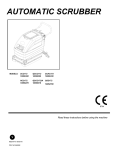
AUTOMATIC SCRUBBER
MODELS:
SCC172
10066320
QSCC172
10066300
SCH172
86218900
SCHC172
10066330
HCC172
10066270
QSCC172IA
10066310
QSCC172IS
10066080
AS17
10066210
AS17B
10066220
AS17T
10066250
AS17TH
10066260
AS17E
10066230
AS17I
10066240
QSC172
10052700
IPX4
Read these instructions before using the machine
G
86221970
PRV NO 980282
MACHINE DATA LOG/OVERVIEW
MODEL _______________________________________
DATE OF PURCHASE __________________________
SERIAL NUMBER ______________________________
SALES REPRESENTATIVE # _____________________
YOUR DEALER
Name: __________________________________________________________________________________________________
Address: _______________________________________________________________________________________________
Phone Number: _________________________________________________________________________________________
OVERVIEW
The Automatic Scrubber is a battery powered, hard floor scrubber intended for commercial
use. The appliance applies a cleaning solution onto a hard floor, scrubs the floor with a brush
or pad, and then vacuums the soiled water back into the recovery tank.
2
86221970 17” SCRUBBER 01/03/07
TABLE OF CONTENTS
Machine Data Log/Overview................................2
Table of Contents.................................................3
HOW TO USE THIS MANUAL
How to use this Manual........................................1-1
SAFETY
Important Safety Instructions ...............................2-1
Hazard Intensity Level..........................................2-2
Safety Label Location...........................................2-3
OPERATIONS
Technical Specifications.......................................3-1
How the Machine Works. .....................................3-3
Components.........................................................3-4
Controls ................................................................3-5
Machine Operation............................................. 3-7
Pre-Run Machine Inspection .......................... 3-7
Filling Solution Tank........................................ 3-7
Scrubbing. ....................................................... 3-7
Emptying & Cleaning Tanks............................ 3-8
MAINTENANCE
Batteries. ..............................................................4-1
Battery Maintenance. ........................................4-1
Checking Battery Specific Gravity.....................4-2
Charging the Batteries. .....................................4-2
Changing Batteries............................................4-3
Battery Connections..........................................4-3
Scrub Brushes......................................................4-4
Types.................................................................4-4
Replacing or Removing Scrub Brushes............4-5
Installing Scrub Brushes ...................................4-5
Squeegee Blades.................................................4-5
Replace Squeegee Blade. ................................4-5
Remove Squeegee Assembly. .........................4-5
Service Schedule. ................................................4-6
Machine Troubleshooting.....................................4-7
PARTS LIST
Decal .................................................................. 5-1
Control Panel-w/Charger.................................... 5-3
Control Panel-SCHC172 w/Charger .................. 5-5
Control Panel-SCH172....................................... 5-7
Control Panel-QSC172....................................... 5-9
Hour Meter ......................................................... 5-11
Handle ................................................................ 5-13
Recovery Tank ................................................... 5-15
Scrub Brush/Pad Driver ..................................... 5-17
Scrub Motor/Lift ................................................. 5-19
Solution Tank .................................................... 5-21
Squeegee .......................................................... 5-23
Squeegee Lift ..................................................... 5-25
Vacuum .............................................................. 5-27
Wheel & Frame .................................................. 5-29
Onboard Charger ............................................... 5-31
Wiring – Battery Cables...................................... 5-33
Wiring – Main Harness – all except QSC172,
SCHC172 & SCH172................................... 5-35
Wiring – Main Harness – SCHC172................... 5-37
Wiring – Main Harness SCH172 ........................ 5-39
Wiring – Main Harness QSC172 ........................ 5-41
Wiring – Schematic – all except QSC172,
SCHC172 & SCH172 ................................... 5-43
Wiring – Schematic – SCH172........................... 5-44
Wiring – Schematic – SCHC172 ........................ 5-45
Wiring – Schematic – QSC172 .......................... 5-46
Suggested Spare Parts ...................................... 5-47
86221970 17” SCRUBBER 01/03/07
3
HOW TO USE THIS MANUAL
The SAFETY section contains important information
regarding hazard or unsafe practices of the
machine. Levels of hazards are identified that could
result in product or personal injury, or severe injury
resulting in death.
This manual contains the following sections:
-
HOW TO USE THIS MANUAL
SAFETY
OPERATIONS
MAINTENANCE
PARTS LIST
The HOW TO USE THIS MANUAL section will tell
you how to find important information for ordering
correct repair parts.
Parts may be ordered from authorized Windsor
dealers. When placing an order for parts, the
machine model and machine serial number are
important. Refer to the MACHINE DATA box which
is filled out during the installation of your machine.
The MACHINE DATA box is located on the inside of
the front cover of this manual.
NOTE: For warranty information, contact your local
dealer or sales representative.
The OPERATIONS section is to familiarize the
operator with the operation and function of the
machine.
The MAINTENANCE section contains preventive
maintenance to keep the machine and its
components in good working condition. They are
listed in this general order:
-
Batteries
Scrub Brushes
Squeegee
Service Schedule
Machine Troubleshooting
The PARTS LIST section contains assembled parts
illustrations and corresponding parts list. The parts
lists include a number of columns of information:
MODEL _____________________________________
-
DATE OF PURCHASE ________________________
SERIAL NUMBER ____________________________
-
SALES REPRESENTATIVE # ___________________
DEALER NAME ______________________________
-
OPERATIONS GUIDE NUMBER __________________
PUBLISHED ________________________________
-
The model and serial number of your machine is on
the front of the electrical panel.
-
REF – column refers to the reference
number on the parts illustration.
PART NO. – column lists the part number
for the part.
PRV NO. – reference number
QTY – column lists the quantity of the
part used in that area of the machine.
DESCRIPTION – column is a brief
description of the part.
SERIAL NO. FROM – column indicates
the first machine the part number is
applicable to. When the machine design
has changed, this column will indicate
serial number of applicable machine. The
main illustration shows the most current
design of the machine. The boxed
illustrations show older designs.
NOTES – column for information not noted
by the other columns.
NOTE: If a service or option kit is installed on your
machine, be sure to keep the KIT INSTRUCTIONS
which came with the kit. It contains replacement
parts numbers needed for ordering future parts.
1-1
86221970 17” SCRUBBER 01/03/07
IMPORTANT SAFETY INSTRUCTIONS
When using a battery powered appliance, basic precaution
must always be followed, including the following:
READ ALL INSTRUCTIONS BEFORE USING THIS MACHINE.
To reduce the risk of fire, electric shock, or injury:
Use only indoors. Do not use outdoors or expose to rain.
Use only as described in this manual. Use only manufacturer’s recommended components
and attachments.
If the machine is not working properly, has been dropped, damaged, left outdoors, or dropped into
water, return it to an authorized service center.
Do not operate the machine with any openings blocked. Keep openings free of debris that may reduce
airflow.
This machine is not suitable for picking up hazardous dust.
Machine can cause a fire when operating near flammable vapors or materials. Do not operate this
machine near flammable fluids, dust or vapors.
This machine is suitable for commercial use, for example in hotels, schools, hospitals, factories, shops
and offices for more than normal housekeeping purposes.
Maintenance and repairs must be done by qualified personnel.
If foam or liquid comes out of machine, switch off immediately.
Disconnect battery before cleaning or servicing.
Before the machine is discarded, the batteries must be removed and properly disposed of.
Make sure all warning and caution labels are legible and properly attached to the machine.
During operation, attention shall be paid to other persons, especially children.
Before use all covers and doors shall be put in the positions specified in the instructions.
When leaving unattended, secure against unintentional movement.
The machine shall only be operated by instructed and authorized persons.
Only chemicals recommended by the manufacturer shall be used.
This appliance has been designed for use with the brushes specified by the manufacturer.
The fitting of other brushes may affect its safety.
Do not use on surfaces having a gradient exceeding 2%.
SAVE THESE INSTRUCTIONS
86221970 17” SCRUBBER 01/03/07
2-1
HAZARD INTENSITY LEVEL
The following symbols are used throughout this guide as indicated in their descriptions:
HAZARD INTENSITY LEVEL
There are three levels of hazard intensity identified by signal words -WARNING and CAUTION and
FOR SAFETY. The level of hazard intensity is determined by the following definitions:
WARNING - Hazards or unsafe practices which COULD result in severe personal injury or death.
CAUTION - Hazards or unsafe practices which could result in minor personal injury or product or
property damage.
FOR SAFETY: To Identify actions which must be followed for safe operation of equipment.
Report machine damage or faulty operation immediately. Do not use the machine if it is not in proper
operating condition. Following is information that signals some potentially dangerous conditions to the
operator or the equipment. Read this information carefully. Know when these conditions can exist.
Locate all safety devices on the machine. Please take the necessary steps to train the machine
operating personnel.
FOR SAFETY:
DO NOT OPERATE MACHINE:
Unless Trained and Authorized.
Unless Operation Guide is Read and understood.
In Flammableor Explosive areas.
In areas with possible falling objects.
WHEN SERVICING MACHINE:
Avoid moving parts. Do not wear loose clothing; jackets, shirts, or sleeves when working on
the machine. Use Windsor approved replacement parts.
Batteries emit hydrogen gas. Explosion or fire can result. Keep sparks and open flame away.
Keep solution tank in raised position when charging. Keep sparks and flames away from the
batteries. Do not smoke around batteries.
Disconnect batteries before working on machine. Only qualified personnel should work inside
machine. Always wear eye protection and protective clothing when working on or near
batteries. Avoid skin contact with the acid contained in the batteries.
Never allow metal to lie across battery tops.
2-2
86221970 17” SCRUBBER 01/03/07
SAFETY LABEL LOCATION
NOTE: These drawings indicate the location of safety labels on the machine. If at any time the labels become
illegible, promptly replace them.
FLAMMABLE
MATERIALS CAN
CAUSE EXPLOSION
OR FIRE.
DO NOT USE OR
PICK UP FLAMMABLE
MATERIAL.
SAFETY LABEL 86252540
PRV NO. 81505
BATTERY CAUTION 86252520
PRV NO. 80885
86221970 17” SCRUBBER 01/24/07
2-3
TECHNICAL SPECIFICATIONS
ITEM
DIMENSION/CAPACITY
Rated Voltage
Rated Amperage
Batteries
Scrub Brush Motor
Vacuum Motor
Mass (GVW)
Weight empty without batteries
Solution Control
Solution tank capacity
Recovery tank capacity
Scrub brush diameter
Scrub brush pressure
Scrub brush speed
Wheels
24 VDC
30 Amps
2 x 12 Volt 105-130 AH
0.75hp (0.56 kw)
24 VDC 2 stage by pass
319 lbs (144.7 kg)
142 lbs (64.4 kg)
Gravity feed, fully variable
8 Gal (30.3 ℓ)
10 Gal (37.9 ℓ)
17 in (430 mm)
33 lbs (15 kg)
200 RPM
2 x 6 in (15 cm) Thermoplastic non
marking
3.0 x 1.0 (75 mm)
286 lbs/in² (1992.6 Kpa)
6700 ft²/hr
Steel with epoxy powdercoat finish
44 in (1110 mm)
2%
Casters
Foundation Pressure
Coverage
Frame Construction
Minimum aisle u-turn width
Maximum rated climb and descent angle with empty
tanks
Maximum rated climb and descent angle with full tanks
3-1
2%
86221970 17” SCRUBBER 01/03/07
TECHNICAL SPECIFICATIONS
ITEM
Height
Length
Width without squeegee
Width of squeegee
Width of scrub path
MEASURE
35 in (0.89 m)
42 in (1.07 m)
20 in (0.51 m)
31 in (0.79 m)
17 in (0.43 m)
Length
Width
Height
SPECIAL NOTES:
The A-weighted sound pressure level emitted by the
appliance was measured to be 74.1 dBA. This is a
space-averaged, broad-band measurement
determined according to IEC 704-I. This appliance
contains no possible source of impact noise.
The overall root-mean-squared acceleration at the
operator’s arms was measured to be less than 1.0
m/s². This is a tri-axial, broadband measurement
made during normal operation on a composite tile
floor.
86221970 17” SCRUBBER 01/03/07
3-2
HOW THIS MACHINE WORKS
This Automatic Scrubber is a battery powered, hard
floor scrubber intended for commercial use. The
appliance applies a cleaning solution onto a hard
floor, scrubs the floor with a brush, and then
vacuums the soiled water back into the recovery
tank.
The machine's primary systems are the solution
system, scrub system and recovery system.
The function of the solution system is to store
cleaning solution and deliver it to the scrub system.
The solution system consists of the solution tank,
strainer, and valve. The solution tank stores cleaning
solution (water and detergent) until it is delivered to
the scrub system. The strainer protects the valve
from debris. The machine has a ball-type valve
which controls the amount of cleaning solution
delivered to the scrub system. The solenoid type
valve controls the delivery of cleaning solution to the
scrub system. The valve automatically prevents
solution flow unless the scrub brushes are turned
on. The solution control lever controls the amount of
cleaning solution delivered to the scrub system.
3-3
The function of the scrub system is to scrub the
floor. The scrub system consists of a rotary type
disk scrub brush, motor, and lift linkage. The brush
scrubs the floor and the motor drives the brush. The
brush lift lever raises and lowers motor and brush.
The function of the recovery system is to vacuum the
soiled water back into the recovery tank. The
recovery system consists of the squeegee, vacuum
motor, screen, and recovery tank. The squeegee
wipes the dirty solution off the floor as the machine
moves forward. The vacuum motor provides suction
to draw the dirty solution off the floor and into the
recovery tank. The screen protects the vacuum fan
from debris. The recovery tank stores the dirty
solution. The float ball in the tank activates when
the recovery tank is full.
86221970 17” SCRUBBER 01/03/07
COMPONENTS
5
1
3
2
4
9
13
7
10
12
11
8
6
1.
2.
3.
4.
5.
6.
7.
8.
Control Panel
Control Handle
Recovery Tank
Recovery Tank Drain Hose
Recovery Tank Domel
Scrub Brush/Pad
Solution Tank
Solution Tank Cover
14
9. Solution Tank Drain Hose
10. Solution Strainer
11. Solution Tank Support Lanyard
12. Squeegee
13. Vacuum Motor
14. Solenoid Valve
86221970 17” SCRUBBER 01/03/07
3-4
CONTROLS
5
9
1
6
4
2
8
7
3
1.
2.
3.
4.
5.
3-5
Solution Control Lever
Brush Switch
Brush Lift Pedal
Vacuum Switch
Squeegee Lift Lever
6.
7.
8.
9.
Battery Charge Level Indicator
Hour Meter
Circuit Breaker
Brush Reverse Switch
86221970 17” SCRUBBER 01/03/07
CONTROLS
1. SOLUTION CONTROL LEVER
Controls solution flow to scrub deck.
To increase flow push the knob forward to the
desired flow.
To decrease flow pull the knob back.
2. BRUSH SWITCH
Controls the scrub brush motor.
To turn scrub brush on, press the top of the
switch.
To turn scrub brush off, press the bottom of the
switch.
3. BRUSH LIFT PEDAL
Raises and lowers the brush.
To lower the brush, push down on pedal and
move to the left.
To raise the brush, lift the lever from its lowered
position.
4. VACUUM SWITCH
Controls the vacuum motor.
To start vacuum motor, press the top of the
switch.
6. BATTERY CHARGE LEVEL INDICATOR
Indicates the charge level of the batteries.
The meter display is divided into 10 vertical
bars. Bars illuminated on the top indicate full
charge. Bars flashing near the bottom indicate
the batteries should be recharged. Further
operation of the machine could damage the
machine or the batteries.
When the machine is left overnight with less
than a full charge, the display may initially
indicate a full charge. It will also indicate a full
charge if the batteries are disconnected, then
reconnected. After a few minutes of operation
the meter will give the correct charge level.
7. HOUR METER
Records the number of hours the machine’s
brush has been in operation. This information is
useful in determining when to service the
machine.
8. CIRCUIT BREAKERS
Circuit breakers interrupt the flow of power in the
event of an electrical overload. When a circuit
breaker is tripped, reset it by pressing the
exposed button. If a circuit breaker continues to
trip, the cause of the electrical overload should
be found and corrected.
25 Amp. Protects the scrub brush
motor.
To stop vacuum motor, press the bottom of the
switch.
25 Amp. Protects the vacuum
motor.
5. SQUEEGEE LIFT LEVER
Raises and lowers the squeegee.
To lower the squeegee, lift and pull the lever to
the right and then lower.
9. BRUSH REVERSE SWITCH
Reverses the scrub brush motor.
To activate, press the top of the switch.
To raise the squeegee, lift the lever and push it
to the left.
86221970 17” SCRUBBER 01/03/07
3-6
MACHINE OPERATIONS
PRE-RUN MACHINE INSPECTION
Do a pre-run inspection to find possible problems
that could cause poor performance or lost time from
breakdown. Follow the same procedure each time to
avoid missing steps.
NOTE: See maintenance section for pre-run
machine inspection checklist items.
FILLING SOLUTION TANK
FOR SAFETY: Before leaving or servicing
machine; stop on level surface, turn off machine.
NORMAL SCRUBBING
Plan the scrubbing pattern in advance. The longest
track is around the perimeter of the area to be
cleaned. For efficient operation, the runs should be
the longest possible without turning, stopping, or
raising and lowering scrub brush/squeegee.
NOTE: In order to achieve the best possible results,
the area that is to be cleaned should be swept
before scrubbing. Large debris, strings & wire must
be removed to prevent being caught in the brush or
squeegee.
1. Turn the machine off.
2. Remove solution tank cover.
3. Fill the solution tank with clean water, leaving
enough room for the required amount of
cleaning solution. The solution tank capacity is
8 gallons (30.3 liters). The water must not be
hotter than 140° F (60°C) to prevent damage to
the tank.
4. Measure the chemical into the solution tank.
Liquid chemicals should be added to the solution
tank after filling with water. Dry chemicals
should be thoroughly mixed before being added
into the solution tank. Commercially available,
high alkaline floor cleaners are suitable for use
in the solution system.
NOTE: Read the chemical manufacturers
recommended proportion instructions.
5. Replace solution tank cover.
Flammable materials can cause an explosion or
fire. Do not use flammable materials in the
tanks.
3-7
86221970 17” SCRUBBER 01/03/07
MACHINE OPERATION
TO BEGIN SCRUBBING
When operating the machine around people, pay
close attention for unexpected movement. Use
extra caution around children.
Flammable liquids and/or reactive metals can
cause explosions or fire! Do not pick up.
The length of time between the first and second
pass depends on the amount of accumulation and
the type of chemical being used. A second
scrubbing with the squeegee down, vacuum on and
again with solution and brush on will further loosen
the soil. The additional application of solution will
further assist the difficult cleaning job.
FOR SAFETY: When using machine, go slow on
inclines and slippery services.
EMPTYING AND CLEANING TANKS
1. Park the machine next to a drain. Drain hoses
are on the rear of the machine.
1. Lower the squeegee.
2. Turn the vacuum on.
2. Turn the machine off.
3. Lower the scrub brush to the floor.
SOLUTION TANK
1. Pull the small drain hose from the retainer.
4. Turn the scrub brush on.
Lower the hose in the direction of the drain.
5. Push machine forward to begin scrubbing.
2. Remove the solution tank cover.
NOTE: Shut machine off immediately if water or
foam is expelled from the machine.
6. Adjust the solution flow as necessary.
3. Flush the solution tank out with clean water and
run several gallons of clean water through
systems. Do not use water hotter than 140°F
(60°C) to clean the tank, damage may occur.
TO STOP SCRUBBING
NOTE: Never allow solution to remain in tank.
Damage to tank, seals and valves could occur.
1. Turn the scrub brush off.
2. Raise the scrub brush.
4. Replace drain hose to retainer.
3. Raise the squeegee.
4. Turn the vacuum off.
DOUBLE SCRUB
For floors, which are heavily soiled or have thick
accumulations of floor finish the machine may not
clean sufficiently with one pass. In these cases it will
be necessary to double scrub. To double scrub,
make the first pass over the surface being cleaned
with the squeegee up, vacuum off, the solution on,
and brush down and on. This allows the solution to
stay in contact with the soil while loosening the
surface accumulation with the brush. Allow time for
the first application to stay in contact with the floor.
RECOVERY TANK
1. Unhook the large drain hose from the retainer.
Lower the hose in the direction of the drain. Do
not stand in front of the end of the hose.
Recovered solution will come out with force.
Slowly remove the plug from the drain hose.
2. Flush the recovery tank out with clean water. Do
not use water hotter than 140°F (60°C) to clean
the tank, damage may occur.
3. Clean off the float and check for free movement
of the float ball.
4. Replace the drain plug and secure the drain
hose in the retainer.
86221970 17” SCRUBBER 01/03/07
3-8
MAINTENANCE
BATTERIES (WET CELL BATTERIES ONLY)
The batteries provide the power to operate the
machine. The batteries require regular maintenance
to keep them operating at peak efficiency.
The machine batteries will hold their charge for long
periods of time, but they can only be charged a
certain number of times. To get the greatest life
from the batteries, charge them when their charge
level reaches 25% of a full charge. Use a
hydrometer to check the charge level.
Do not allow the batteries to remain in a discharged
condition for any length of time. Never expose a
discharged battery to temperatures below freezing.
Discharged batteries will freeze causing cracked
cases. Do not operate the machine if the batteries
are in poor condition or if they have a charge level
below 25% (specific gravity below 1.155).
Keep all metallic objects off the top of the batteries,
as they may cause a short circuit. Replace worn or
damaged cables and terminals.
Check the electrolyte level in each battery cell
before and after charging the batteries. Never add
acid to the batteries, use distilled water. Do not
allow water level to fall below the battery plates.
Portions of plates exposed to air will be destroyed.
Do not overfill. Keep plugs firmly in place at all
times.
When servicing machine, avoid contact with
battery acid.
Batteries emit hydrogen gas. Explosion or fire
can result. Keep sparks and open flame away.
Keep covers open when charging.
Wear eye protection and protective clothing
when working with batteries.
Charge batteries in a well ventilated area.
BATTERY MAINTENANCE
1. When cleaning the batteries, use a solution of
baking soda and water. Do not allow the
cleaning fluid to enter the battery cells,
electrolyte will be neutralized.
2. Maintain the proper electrolyte level in each
battery cell. If a cell should accidentally
overflow, clean immediately.
3. Wipe off the top of the batteries at least once a
week.
4. Test battery condition with a hydrometer at least
once a week.
5. Ensure that all connections are tight and all
corrosion removed.
6. Every 4 to 6 months remove the batteries from
the machine and clean the battery cases and
battery compartment.
4-1
86221970 17” SCRUBBER 01/03/07
MAINTENANCE
CHECKING BATTERY SPECIFIC GRAVITY
Use a hydrometer to check the battery specific
gravity.
TO CHARGE THE BATTERIES
When servicing machine, avoid contact with
battery acid.
Batteries emit hydrogen gas. Explosion or fire
can result. Keep sparks and open flame away.
Keep covers open when charging.
Battery Check
Wear eye protection and protective clothing
when working with batteries.
Charge batteries in a well ventilated area. Leave
the solution tank open.
CHECKING GRAVITY
A. Hydrometer
B. Battery
NOTE: Do not take readings immediately after
adding distilled water, if the water and acid are not
thoroughly mixed, the reading may not be accurate.
Check the hydrometer readings against this chart.
SPECIFIC GRAVITY
@ 80° F (27°C)
1.265
1.225
1.190
1.155
1.120
BATTERY CONDITION
100% CHARGED
75% CHARGED
50% CHARGED
25% CHARGED
DISCHARGED
MACHINES EQUIPPED WITH ONBOARD
CHARGER
1. Fully open Recovery Tank/Battery Cover or prop
in partially open position using bracket
(included). This will provide additional venting of
batteries during charging cycle.
2. Connect charger’s AC power cord to AC mains.
The charger’s YELLOW “AC” LED will light.
NOTE: When charger is energized, all machine
function will shut down.
3. After several seconds, the charger’s green LED
will flash to indicate that charging is in process.
NOTE: If the readings are taken when the battery
electrolyte is any temperature other than 80°F
(27°C), the reading must be temperature corrected.
NOTE: If no lights are illuminated, or yellow LED
flashes, refer to the charger Product Manual
Troubleshooting section.
To find the corrected specific gravity reading when
the temperature of the battery electrolyte is other
than 80°F (27°): Add (+) to the specific gravity
reading 0.004 (4 points), for each 10°F (6°C) above
80° (27°C).
Subtract (-) from the specific reading 0.004 (4
points), for each 10°F (6°C) below 80°F (27°C)
4. When charging is complete, both the yellow and
green LEDs will remain on. The charger is now
in standby mode.
5. Disconnect charger’s AC power cord.
6. Raise battery cover and check the battery
electrolyte level. It should be up to the indicator
ring. If necessary, add distilled water.
7. Lower the battery cover
NOTE: For additional information about battery
charger function, please see the charger Product
Manual.
86221970 17” SCRUBBER 01/03/07
4-2
MAINTENANCE
MACHINES WITHOUT ONBOARD CHARGER
CHANGING BATTERIES
Use a 24 volt, 12 amp maximum output, DC charger
which will automatically shut off when the batteries
are fully charged to charge the two battery pack.
Stop the machine in a clean area next to the
charger. Turn off machine.
1. Stop the machine in a clean, well ventilated area
next to the charger.
FOR SAFETY: Before leaving or servicing the
machine; stop on level surface, turn off machine.
1. Drain recovery tank and raise the recovery tank.
2. Turn the machine off.
2. Disconnect battery pack from machine.
FOR SAFETY: Before leaving or servicing
machine; stop on level surface, turn off machine.
3. Disconnect squeegee lift cable and vacuum
hose.
3. Drain recovery tank and raise the recovery tank.
4. Prepare a suitable site to place the batteries.
Batteries emit hydrogen gas. Explosion or fire
can result. Keep sparks and open flame away.
Keep covers open when charging.
4. Check the electrolyte level in each battery cell.
Before charging, add just enough distilled water
to cover the plates. After charging is complete,
add just enough distilled water to bring up the
level to the indicator ring. If the water level is
too high before charging, normal expansion rate
of the electrolyte may cause an overflow.
Resulting in a loss of battery acid balance and
damage the machine.
5. Pull battery tray with batteries out of rear of
machine.
Batteries are a potential environmental hazard.
Consult your battery supplier for safe disposal
methods.
+ red
- blk
- blk
+ red
5. Replace the battery caps, and leave them in
place while charging.
6. Unplug the battery connector from the machine.
FOR SAFETY: When charging, connect the
charger to the batteries before connecting the
charger to the AC wall outlet. Never connect the
charger to the AC wall outlet first. Hazardous
sparks may result.
7. Plug the charger connector into the battery
connector. Connect the charger AC plug to a
wall outlet. The charger gauge should indicate
that the batteries are charging.
8. When the batteries are fully charged, disconnect
the charger from the AC wall outlet, then
disconnect the charger from the batteries.
9. Connect the batteries to the machine connector.
10. Check the electrolyte level. It should be up to
the indicator ring. If necessary, add distilled
water.
11. Lower the recovery tank.
4-3
86221970 17” SCRUBBER 01/03/07
MAINTENANCE
SCRUB BRUSHES
FINISHED FLOORS
NOTE: All original equipment brushes are equipped
with “Perform Alert©”. This feature will tell the
operator when it is time to replace the scrub brush.
“Perform Alert©” brushes have pre-trimmed bright
yellow tufts to indicate the length of a worn out
brush. When the tufts in the scrub brush wear to a
length equal to the yellow tufts, the scrub brush
should be replaced.
Nylon bristles are used in a variety of applications
on coated or uncoated surfaces.
There are three different types of brushes available
to cover applications from cleaning heavily soiled
floors to polishing. A pad driver is also available to
take advantage of the many cleaning pads on the
market and further add to the flexibility of the Saber
Compact. Please refer to the following to assist in
selecting the proper brush or pad for the work at
hand.
UNCOATED FLOORS
Mild Grit is a less aggressive silicone carbide grit
suitable for cleaning medium soil conditions.
Advantages are faster ground speed than nylon
bristles on light solid applications.
Polypropylene is a general-purpose scrub brush
with stiff bristles. Polypropylene works well for
maintaining concrete, wood and tile floors.
White Pads (Polishing) are used for dry polishing to
achieve a high-gloss appearance, or surface
washing on highly polished or burnished floors.
Red Pads (Buffing) are used for light-duty
scrubbing. When used with a mild detergent they
will provide surface cleaning without removing the
finish.
Blue Pads (Scrubbing) are used for heavy-duty
scrubbing and light stripping. The blue pads remove
less finish than brown stripping pads, yet will remove
black marks, stains and dirt.
Brown Pads (Stripping) are used for easy and
complete removal of old floor waxes/finishes. They
will quickly remove ground in dirt, black heel marks,
and spills. When used with the proper stripper, this
pad leaves the floor clean and ready for finishing.
The scrub brush should be checked before each
days work for wire, string, wear and damage. The
scrub brush should be replaced if brush bristles are
missing or if yellow Perform Alert © indicates
minimum brush length.
86221970 17” SCRUBBER 01/03/07
4-4
MAINTENANCE
REPLACING OR REMOVING SCRUB BRUSHES
SQUEEGEE BLADES
1. Turn the machine off.
The front squeegee blade allows solution to pass
through channels in the blade into the squeegee
assembly while maintaining vacuum to provide lift.
FOR SAFETY: Before leaving or servicing the
machine; stop on level surface, turn OFF
machine.
2. Raise the scrub deck up by pushing down on the
The rear blade wipes the floor to a near dry
condition. It is important the rear blade be in good
condition to properly do its job.
pedal.
3. Locate the brush reverse switch on the rear of
the panel. Press to activate the motor then
release to disconnect brush driver.
Check both the front and rear squeegee blades for
damage and wear each day in the pre-run check.
Change the front blade if it is torn or has an uneven
edge. Change the rear blade if it is less than 1/2 the
original thickness.
TO REMOVE SQUEEGEE ASSEMBLY
1. With the squeegee in the up position, turn the
machine power off.
4. Tilt and pull machine back to expose brush
2. Loosen both squeegee knobs and pull squeegee
assembly rearward from the lifting carrier.
driver.
3. Inspect or repair as necessary and reinstall.
TO REPLACE SQUEEGEE BLADES
INSTALLING SCRUB BRUSHES
1. With the squeegee in the up position, turn the
machine power off.
1. Turn the machine off.
FOR SAFETY: Before leaving or servicing the
machine; stop on level surface, turn OFF
machine.
FOR SAFETY: Before leaving or servicing
machine; stop on level surface, turn off machine.
2. Remove the squeegee assembly from the
2. Tilt and push machine over brush driver. The
brush centering bracket will position the brush
driver.
machine. Remove all screws and remove blade
retainer strap and remove squeegee blade.
3. Replace squeegee blades as required.
4. Install squeegee blade.
3. Lower the scrub deck by pushing the pedal
5. Install squeegee retainer strap.
down and to the left.
6. Install all screws starting from center and
working to ends.
4. Locate the brush switch and turn on.
4-5
86221970 17” SCRUBBER 01/03/07
MAINTENANCE
SERVICE SCHEDULE
Before
starting
the work
period
End of work
period
before
storing
MAINTENANCE
Check battery acid level
Check vac hose connections
Clean the squeegee blades
Inspect brush or pad for debris:
wire string, wear
Inspect float ball screen
DAILY
*
*
*
*
MONTHLY
ANNUALLY
*
Drain & rinse tanks
*
Raise squeegee assembly
Raise scrub deck assembly
Charge the batteries.
Remove the pad driver/brush
Check the brush/pad for damage
and/or wear
Clean squeegee blades
Clean recovery tank shut off &
screen
*
*
*
*
*
Check battery cells w/ hydrometer
Check solution strainer
Check pivot points and casters for
proper lubrication
Inspect tank and hoses
WEEKLY
*
*
*
*
*
*
Clean tops of batteries
Check battery cable clamps
Use a vacuum to remove lint from
the motor windings
Grease casters
Inspect all motors for carbon
motor brush wear
86221970 17” SCRUBBER 01/03/07
*
*
*
*
*
4-6
TROUBLESHOOTING
PROBLEM
Poor or no water pick-up
CAUSE
Debris caught on squeegee
SOLUTION
Remove debris
Worn squeegee blades
Replace squeegee blades
Vacuum hose clogged
Clear obstruction from hose
Vacuum hose disconnected
from squeegee or recovery
tank
Vacuum hose damaged
Reconnect vacuum hose
Vacuum motor inlet screen
dirty
Recovery tank not sealed
Clean inlet screen
Recovery tank full
Check vacuum motor
position. Replace damaged
seal.
Empty recovery tank
Use less or different
detergent
Use defoamer
Drain recovery tank
Circuit breaker tripped
Reset circuit breaker
Loose connection
Check motor wires and
connections
Replace contactor
Foam filling recovery tank
Vacuum motor does not run, or runs
slowly
Faulty vacuum contractor
Worn vacuum motor brushes
Poor scrubbing performance
Debris caught in scrub brush
Worn brush or pad
Brush motor does not run, or runs
slowly
Replace brushes, check
commutator
Remove debris
Replace brush or pad
Improper detergent, brush or
pad used
Low scrub brush down
pressure
Low battery charge
Contact equipment or
application specialist
Increase brush pressure
Circuit breaker tripped
Reset circuit breaker
Loose connection
Check motor wires and
connection
Replace contactor
Faulty brush motor contactor
Worn brush motor brushes
4-7
Replace vacuum hose
86221970 17” SCRUBBER 01/03/07
Charge batteries
Replace brushes, check
commutator
TROUBLESHOOTING
PROBLEM
CAUSE
SOLUTION
Little or no solution flow to the floor
Solution tank empty
Fill solution tank
Solution flow turned off or set
too low
Solution strainer plugged
Turn on or increase flow
setting
Clean solution strainer
Solution hoses obstructed
Clear obstruction from hose
Solution solenoid valve
obstructed or stuck
Battery disconnected
Clean or replace
No power to machine
Little or no propel
Emergency shut-off activated
Check all battery cable
connections
Reset
Battery connections corroded
Faulty main contactor
Clean connections
Replace contactor
Faulty power switch
Replace switch
Low battery charge
Machine turned on with
directional control button(s)
not in neutral
Controller overheated
Loose connection
Charge batteries
Allow control button to return
to neutral. Restart
86221970 17” SCRUBBER 01/03/07
Allow cool down period
Check motor wires and
connection
4-8
NOTES:
4-9
86221970 17” SCRUBBER 01/03/07