1
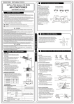
USER'S MANUAL
ARCTIC SERIES
outdoor unit
ASH-13AIA PT, ASH-18AIA PT
„Original instruction“
Precautions
WARNING
Operation and Maintenance
This appliance can be used by children aged from 8
years and above and persons with reduced physical,
sensory or mental capabilities or lack of experience
and knowledge if they have been given supervision or
instruction concerning use of the appliance in a safe
way and understand the hazards involved.
Children shall not play with the appliance.
Cleaning and user maintenance shall not be made by
children without supervision.
Do not connect air conditioner to multi-purpose socket.
Otherwise, it may cause fire hazard.
Do disconnect power supply when cleaning air
conditioner. Otherwise, it may cause electric shock.
.
If the supply cord is damaged, it must be replaced by
the manufacturer, its service agent or similarly qualified
persons in order to avoid a hazard.
Do not wash the air conditioner with water to avoid
electric shock.
Do not spray water on indoor unit. It may cause electric
shock or malfunction.
After removing the filter, do not touch fins to avoid injury.
Do not use fire or hair dryer to dry the filter to avoid
deformation or fire hazard.
2
Precautions
WARNING
Maintenance must be performed by qualified
professionals. Otherwise, it may cause personal injury
or damage.
Do not repair air conditioner by yourself. It may cause
electric shock or damage. Please contact dealer when
you need to repair air conditioner.
Do not extend fingers or objects into air inlet or air
outlet. It may cause personal injury or damage.
Do not block air outlet or air inlet. It may cause
malfunction.
Do not spill water on the remote controller, otherwise the
remote controller may be broken.
When below phenomenon occurs, please turn off air
conditioner and disconnect power immediately, and then
contact the dealer or qualified professionals for service.
● Power cord is overheating or damaged.
● There’s abnormal sound during operation.
● Circuit break trips off frequently.
● Air conditioner gives off burning smell.
● Indoor unit is leaking.
If the air conditioner operates under abnormal conditions,
it may cause malfunction, electric shock or fire hazard.
When turning on or turning off the unit by emergency
operation switch, please press this switch with an insulating
object other than metal.
Do not step on top panel of outdoor unit, or put heavy
objects. It may cause damage or personal injury.
3
Precautions
WARNING
Attachment
Installation must be performed by qualified professionals.
Otherwise, it may cause personal injury or damage.
Must follow the electric safety regulations when installing
the unit.
According to the local safety regulations, use qualified
power supply circuit and circuit break.
Do install the circuit break. If not, it may cause malfunction.
An all-pole disconnection switch having a contact separation
of at least 3mm in all poles should be connected in fixed
wiring.
Including an circuit break with suitable capacity, please
note the following table.Air switch should be included
magnet buckle and heating buckle function, it can protect
the circuit-short and overload.
Air Conditioner should be properly grounded. Incorrect
grounding may cause electric shock.
Don't use unqualified power cord.
Make sure the power supply matches with the
requirement of air conditioner.Unstable power supply or
incorrect wiring or malfunction. Please install proper power
supply cables before using the air conditioner.
Properly connect the live wire, neutral wire and
grounding wire of power socket.
Be sure to cut off the power supply before proceeding
any work related to electricity and safety.
4
Precautions
WARNING
Do not put through the power before finishing installation.
If the supply cord is damaged, it must be replaced by
the manufacturer, its service agent or similarly qualified
persons in order to avoid a hazard.
The temperature of refrigerant circuit will be high, please
keep the interconnection cable away from the copper
tube.
The appliance shall be installed in accordance with
national wiring regulations.
Installation must be performed in accordance with the
requirement of NEC and CEC by authorized personnel
only.
The air conditioner is the first class electric appliance. It
must be properly grounding with specialized grounding
device by a professional. Please make sure it is always
grounded effectively, otherwise it may cause electric shock.
The yellow-green wire in air conditioner is grounding
wire, which can't be used for other purposes.
The grounding resistance should comply with national
electric safety regulations.
The appliance must be positioned so that the plug is
accessible.
All wires of indoor unit and outdoor unit should be
connected by a professional.
If the length of power connection wire is insufficient, please
contact the supplier for a new one. Avoid extending the
wire by yourself.
5
Precautions
WARNING
For the air conditioner with plug, the plug should be
reachable after finishing installation.
For the air conditioner without plug, an circuit break
must be installed in the line.
If you need to relocate the air conditioner to another
place, only the qualified person can perform the work.
Otherwise, it may cause personal injury or damage.
Select a location which is out of reach for children and
far away from animals or plants.If it is unavoidable,
please add the fence for safety purpose.
The indoor unit should be installed close to the wall.
Working temperature range
Maximum cooling
Maximum heating
Indoor side DB/WB(°C)
32/23
27/-
NOTICE:
Outdoor side DB/WB(°C)
54/26
24/18
● The operating temperature range (outdoor temperature) for cooling is -18℃~54℃;
The operating temperature range (outdoor temperature) for heating is -30°C~24°C
is -15℃~24 Heating temperature range for the model with electric heating belt
for chassis is -30℃~24℃ .
6
Parts name
Outdoor Unit
air inlet
Connection wire
air outlet
NOTICE:
Actual product may be different from above graphics, please refer to actual
products.
7
he
ot
e t tion
c
a c
Sp stru
st
ob
lea
t
A cm
30
At least 50cm
Space to the obstruction
Installation dimension diagram
Drainage pipe
At least 30cm
Space to th
e wall
Sp
ac
o
et
the
ob
At
on
cti
u
str
s
lea
At least 50cm
m
0c
0
t2
Space to the
obstruction
8
Tools for installation
1 Level meter
2 Screw driver
3 Impact drill
4 Drill head
5 Pipe expander
6 Torque wrench
7 Open-end wrench
8 Pipe cutter
9 Leakage detector
10 Vacuum pump
11 Pressure meter
12 Universal meter
13 Inner hexagon spanner
Note:
14 Measuring tape
● Please contact the local agent for installation.
Selection of installation location
Basic requirement
Installing the unit in the following places maycause malfunction. If it is unavoidable, please consult the localdealer:
1.The place with strong heat sources, vapors, flammableor explosive gas, or
volatile objects spread in the air.
2.The place with high-frequency devices (such as welding machine, medical
equipment).
3. The place near coast area.
4. The place with oil or fumes in the air.
5. The place with sulfureted gas.
6. Other places with special circumstances.
7. The appliance shall not be installed in the laundry.
Outdoor unit
will not affect neighborhood.
2. The location should be well ventilated and dry, in which the outdoor unit
won't be exposed directly to sunlight or strong wind.
3. The location should be able to withstand the weight of outdoor unit.
4. Make sure that the installation follows the requirement of installation
dimension diagram.
5. Select a location which is out of reach for children and far away from animals
or plants.If it is unavoidable, please add the fence for safety purpose.
9
Requirements for electric connection
Safety precaution
1. Must follow the electric safety regulations when installing the unit.
air switch.
3. Make sure the power supply matches with the requirement of air conditioner.
Unstable power supply or incorrect wiring or malfunction. Please install proper
power supply cables before using the air conditioner.
4. Properly connect the live wire, neutral wire and grounding wire of power socket.
5. Be sure to cut off the power supply before proceeding any work related to
electricity and safety.
7. If the supply cord is damaged, it must be replaced by the manufacturer, its
8. The temperature of refrigerant circuit will be high, please keep the interconnection cable away from the copper tube.
9. The appliance shall be installed in accordance with national wiring regulations.
Grounding requirement
grounding with specialized grounding device by a professional. Please make
sure it is always grounded effectively, otherwise it may cause electric shock.
2. The yellow-green wire in air conditioner is grounding wire, which can't be used
for other purposes.
3. The grounding resistance should comply with national electric safety regulations.
4. The appliance must be positioned so that the plug is accessible.
5. An all-pole disconnection switch having a contact separation of at least 3mm in
For models with a power plug, make
sure the plug is within reach after installation;
6. Including an air switch with suitable capacity, please note the following table. Air
switch should be included magnet buckle and heating buckle function, it can
protect the circuit-short and overload. (Caution: please do not use the fuse only
for protect the circuit)
Air-conditioner
Air switch capacity
13K、18K
16A
10
Installation of outdoor unit
Step one: fix the support of outdoor unit
(select it according to the actual installation situation)
1. Select installation location according to the house structure.
2. Fix the support of outdoor unit on the selected location with expansion screws.
Note:
● Take sufficient protective measures when
installing the outdoor unit.
● Make sure the support can withstand at least
four times of the unit weight.
● The outdoor unit should be installed at least
3cm above the floor in order to install drain
joint.
● For the unit with cooling capacity of 2300W
~5000W, 6 expansion screws are needed;
for the unit with cooling capacity of 6000W
~8000W, 8 expansion screws are needed;
for the unit with cooling capacity of 10000W at least 3cm above the floor
~16000W, 10 expansion screws are needed.
Step three: fix outdoor unit
Step two: install drain joint
(Only for cooling and heating
unit)
1. Place the outdoor unit on the
support.
2. Fix the foot holes of outdoor unit
with bolts.
1. Connect the outdoor drain joint into
the hole on the chassis, as shown in
the picture below.
2. Connect the drain hose into the drain
vent.
drain vent
Drain hose
foot holes
foot holes
chassis
outdoor drain joint
11
Installation of outdoor unit
Step four: connect indoor and outdoor pipes
1. Remove the screw on the right handle of outdoor unit and then remove
the handle.
3. Pretightening the union nut with
hand.
pipe joint
screw
union nut
handle
2. Remove the screw cap of valve and
aim the pipe joint at the bellmouth of
pipe.
4. Tighten the union nut with torque
wrench by referring to the sheet
below.
torque
Hex nut diameter Tightening
(N.m)
Φ6
15~20
Φ 9.52
30~40
Φ 12
45~55
Φ 16
60~65
Φ 19
70~75
liquid pipe
liquid
valve
gas pipe
gas valve
1. Remove the wire clip; connect the power connection wire and signal control
wire (only for cooling and heating unit) to the wiring terminal according to the
18K:
13K:
N(1)
N
3
N(1)
L
blue
blue
2
brown
black brown yellowgreen
yellowgreen
L
N
yellowgreen
blue
black
2
3
brown
L
brown
L
12
blue
POWER
Indoor unit connection
handle
N
Indoor unit connection
N
POWER
yellowgreen
Installation of outdoor unit
2. Fix the power connection wire and signal control wire with wire clip (only for
cooling and heating unit).
Note:
● After tighten the screw, pull the power cord slightly to check if it is firm.
● Never cut the power connection wire to prolong or shorten the distance.
Step six: neaten the pipes
1. The pipes should be placed along the wall,
bent reasonably and hidden possibly. Min.
semidiameter of bending the pipe is 10cm.
2. If the outdoor unit is higher than the wall
hole, you must set a U-shaped curve in the
pipe before pipe goes into the room, in
order to prevent rain from getting into the
room.
wall
U-shaped curve
drain hose
Note:
● The through-wal height of drain hose
shouldn't be higher than the outlet
pipe hole of indoor unit.
● Slant the drain hose slightly downwards. The drain hose can't be
curved, raised and fluctuant, etc.
the drain hose
can't raise
upwards.
The drain hose can't be fluctuant
● The water outlet can't be placed
in water in order to drain smoothly.
The drain hose
can't be fluctuant
The water outlet
can't be placed
in water
13
The water
outlet can't be
fluctuant
Vacuum pumping
Use vacuum pump
1. Remove the valve caps on
liquid valve
the liquid valve and gas
piezometer
Lo
Hi
valve and the nut of refrigas valve
gerant charging vent.
valve cap
2. Connect the charging hose refrigerant charging
of piezometer to the refri- vent
gerant charging vent of gas nut of refrigerant
valve and then connect the charging vent
other charging hose to the
vacuum pump
vacuum pump.
3. Open the piezometer cominner hexagon
pletely and operate for
spanner
10-15min to check if the
pressure of piezometer remains in -0.1MPa.
close
4. Close the vacuum pump
open
and maintain this status for
1-2min to check if the pressure of piezometer remains
in -0.1MPa. If the pressure decreases, there may be leakage.
5. Remove the piezometer, open the valve core of liquid valve and gas valve
completely with inner hexagon spanner.
6. Tighten the screw caps of valves and refrigerant charging vent.
7. Reinstall the handle.
Leakage detection
1. With leakage detector:
Check if there is leakage with leakage detector.
2. With soap water:
If leakage detector is not available, please use soap water for leakage detection.
Apply soap water at the suspected position and keep the soap water for more
than 3min. If there are air bubbles coming out of this position, there's a leakage.
14
Check after installation
● Check according to the following requirement after finishing installation.
Items to be checked
Possible malfunction
Has the unit been installed firmly?
The unit may drop, shake or emit noise.
Have you done the refrigerant leakage
test?
It may cause insufficient cooling
(heating) capacity.
Is heat insulation of pipeline sufficient?
It may cause condensation and water
dripping.
Is water drained well?
It may cause condensation and water
dripping.
Is the voltage of power supply according to the voltage marked on the
nameplate?
It may cause malfunction or damaging
the parts.
Is electric wiring and pipeline installed
correctly?
It may cause malfunction or damaging
the parts.
Is the unit grounded securely?
It may cause electric leakage.
Does the power cord follow the specification?
It may cause malfunction or damaging
the parts.
Is there any obstruction in the air inlet
and outlet?
It may cause insufficient cooling
(heating) capacity.
The dust and sundries caused during
installation are removed?
It may cause malfunction or damaging
the parts.
The gas valve and liquid valve of
connection pipe are open completely?
It may cause insufficient cooling
(heating) capacity.
Test operation
1. Preparation of test operation
● The client approves the air conditioner.
● Specify the important notes for air conditioner to the client.
2. Method of test operation
● Put through the power, press ON/OFF button on the remote controller to start
operation.
● Press MODE button to select AUTO, COOL, DRY, FAN and HEAT to check
whether the operation is normal or not.
● If the ambient temperature is lower than 16℃ , the air conditioner can’t
start cooling.
15
Configuration of connection pipe
1. Standard length of connection pipe
● 5m, 7.5m, 8m.
2.Min. length of connection pipe is 3m.
3.Max. length of connection pipe and max. high difference.
Cooling
capacity
Max length
Max height
of connecdifference
tion pipe
Cooling
capacity
Max length
Max height
of connecdifference
tion pipe
5000Btu/h
(1465W)
15
5
24000Btu/h
(7032W)
25
10
7000Btu/h
(2051W)
15
5
28000Btu/h
(8204W)
30
10
9000Btu/h
(2637W)
15
5
36000Btu/h
(10548W)
30
20
12000Btu/h
(3516W)
20
10
42000Btu/h
(12306W)
30
20
18000Btu/h
(5274W)
25
10
48000Btu/h
(14064W)
30
20
4. The additional refrigerant oil and refrigerant charging required after prolonging
connection pipe
● After the length of connection pipe is prolonged for 10m at the basis of
standard length, you should add 5ml of refrigerant oil for each additional 5m
of connection pipe.
● The calculation method of additional refrigerant charging amount (on the basis
of liquid pipe):
Additional refrigerant charging amount = prolonged length of liquid pipe ×
additional refrigerant charging amount per meter
● Basing on the length of standard pipe, add refrigerant according to the
requirement as shown in the table. The additional refrigerant charging amount
per meter is different according to the diameter of liquid pipe. See the
following sheet.
16
Configuration of connection pipe
Additional refrigerant charging amount for R410A
Diameter of connection pipe
Outdoor unit throttle
Liquid pipe(mm)
Gas pipe(mm)
Cooling only(g/m) Cooling and heating(g/m)
Φ6
Φ9.52 or Φ12
15
20
Φ6 or Φ9.52
Φ16 or Φ19
15
50
Φ12
Φ19 or Φ22.2
30
120
Φ16
Φ25.4 or Φ31.8
60
120
Φ19
_
250
250
Φ22.2
_
350
350
17
Pipe expanding method
Note:
Improper pipe expanding is the main cause of refrigerant leakage. Please expand
the pipe according to the following steps:
A: Cut the pipe
● Confirm the pipe length according to
the distance of indoor unit and
outdoor unit.
● Cut the required pipe with pipe cutter.
E: Expand the port
● Expand the port with expander.
hard
mold
expander
pipe
pipe
pipe cutter
leaning
uneven
Note:
● "A" is different according to the
diameter, please refer to the sheet
below:
burr
B: Remove the burrs
● Remove the burrs with shaper and
prevent the burrs from getting into
the pipe.
pipe
shaper
downwards
A(mm)
Outer diameter
(mm)
Max
Min
Φ6-6.35(1/4")
1.3
0.7
Φ9.52(3/8")
1.6
1.0
Φ12-12.7(1/2")
1.8
1.0
Φ15.8-16(5/8")
2.4
2.2
F: Inspection
● Check the quality of expanding port.
If there is any blemish, expand the
port again according to the steps
above.
C: Put on suitable insulating pipe
D: Put on the union nut
● Remove the union nut on the indoor
connection pipe and outdoor valve;
install the union nut on the pipe.
smooth surface
improper expanding
union pipe
leaning
pipe
the length is equal
18
damaged
surface
crack
uneven
thickness
ELECTRIC SCHEMATIC DIAGRAM
ASH-13AIA PT outdoor
ASH-18AIA PT outdoor
19
RATING LABEL
20
ENERGY LABEL
21
NOTE CONCERNING PROTECTION OF ENVIRONMENT
This product must not be disposed of via normal household waste after its
service life, but must be taken to a collection station for the recycling of
electrical and electronic devices. The symbol on the product, the
operating instructions or the packaging indicate such disposal procedures.
The materials are recyclable in accordance with their respective symbols. By means
of re-use, material recycling or any other form of recycling old appliances you are
making an important contribution to the protection of our environment. Please ask
your local council where your nearest disposal station is located.
INFORMATION CONCERNING USED REFRIGERANT
MEDIUM
This unit is containing fluorinated gases included in the Kyoto protocol. The
maintanance and the liquidation must be carried out by qualified personel.
Type of refrigerant: R410A
The composition of the cooling medium R410A: (50% HFC-32, 50% HFC-125)
The quantity of the refrigerant: please see the unit label.
The value GWP: 2088
GWP = Global Warming Potential
In case of quality problem or other please contact your local supplier or authorized
service center.
Emergency number: 112
PRODUCER
Producer: SINCLAIR CORPORATION Ltd., 1-4 Argyll St., London W1F 7LD, UK,
www.sinclair-eu.com
This product was manufactured in China (Made in China).
REPRESENTATIVE, TECHNICAL SUPPORT
NEPA spol. s r.o.
Purkyňova 45
612 00 Brno
Czech Republic
Tel.: +420 541 590 140
Fax: +420 541 590 124
www.nepa.cz
[email protected]
22