1
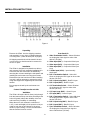
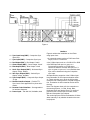
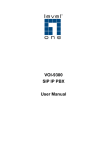
“Perfecting Video with a
No-Compromise Approach
for Reproducing
the Ultimate Film Experience”
The Faroudja
VP301 Video Processor
With Picture Plus™ Technology
Installation & Operation
Instructions
ª
TABLE OF CONTENTS
History . . . . . . . . . . . . . . . . . . . . . . . . . . . . . . . . . . . . . . . . . . . . . . . . . . . . 2
Licensees and Awards . . . . . . . . . . . . . . . . . . . . . . . . . . . . . . . . . . . . . . . . 3
System Description . . . . . . . . . . . . . . . . . . . . . . . . . . . . . . . . . . . . . . . . . . 4
Inventory List . . . . . . . . . . . . . . . . . . . . . . . . . . . . . . . . . . . . . . . . . . . . . . . 5
Caution Notes . . . . . . . . . . . . . . . . . . . . . . . . . . . . . . . . . . . . . . . . . . . . . . 5
Technical Highlights . . . . . . . . . . . . . . . . . . . . . . . . . . . . . . . . . . . . . . . . . . 6
Installation Instructions. . . . . . . . . . . . . . . . . . . . . . . . . . . . . . . . . . . . . . . . 8
Rear Panel I/O . . . . . . . . . . . . . . . . . . . . . . . . . . . . . . . . . . . . . . . . . . . 8
Interface . . . . . . . . . . . . . . . . . . . . . . . . . . . . . . . . . . . . . . . . . . . . . . . . 9
Operating Instructions . . . . . . . . . . . . . . . . . . . . . . . . . . . . . . . . . . . . . . . 10
Troubleshooting . . . . . . . . . . . . . . . . . . . . . . . . . . . . . . . . . . . . . . . . . . . . 12
Appendix A: Remote Control Operation. . . . . . . . . . . . . . . . . . . . . . . . . . 13
Specifications . . . . . . . . . . . . . . . . . . . . . . . . . . . . . . . . . . . . . . . . . . . . . . 16
Copyright©1998 by Faroudja Laboratories, Inc.
No part of this document may be copied, photocopied, reproduced, translated, or reproduced by any electronic
medium or machine readable form without prior consent, in writing, from Faroudja Laboratories, Inc.
The Faroudja Laboratories VP301 Line Multiplier is covered by the following United States patents: 4,030,121,
4,179,705, 4,240,105, 4,262,304, 4,847, 681, 4,864,389, 4,876,596, 4,893,176, 4,916,526, 4,967,271,
4,982,280, 4,989,090, 5,014,119, 5,025,312, 5,159,451, 5,237,414.
All Rights Reserved.
HISTORY
Some Video History and the Faroudja Approach
Faroudja Laboratories, located in northern CaliforniaÕs Silicon Valley, was founded in 1971 by Yves
and Isabell Faroudja to develop state-of-the-art
video processing technology. Over the last 26
years, Faroudja Laboratories has developed
hundreds of advanced electronic processes to
improve video enhancement, noise reduction and
NTSC encoding/ decoding technologies. Many of
these processes are used under license by
the worldÕs leading electronics companies in a
wide range of high performance video products.
Faroudja professional video equipment is also
currently hard at work in hundreds of television
studios. Thus Faroudja technology is utilized and
enjoyed in millions of American homes every day.
motion pictures. In pursuit of this goal, Faroudja
Laboratories has made use of techniques from
Faroudja professional video equipment and incorporated these in the VP201/VP251 line doublers,
VP401/VP401U Line Quadruplers and now the
VP301. FaroudjaÕs unique approach focuses on
critical problem areas in the NTSC and PAL broadcast format. With patented engineering and design
work, Yves and Faroudja Laboratories have created an exceptional product that brings new levels of
visual reality to the enjoyment of discerning video
enthusiasts around the world.
This booklet will provide the reader with a handson look at the VP301, its operation and benefits.
Also supplied is an overview of the proprietary
technologies utilized in this extraordinary device
and an explanation of the visual improvements it
provides in home video and corporate playback
systems.
Yves Faroudja has devoted his career and his
company to the goal of enabling home video
systems to achieve the image quality of 35mm
2
LICENSEES AND AWARDS
On June 24, 1998 Yves Faroudja was awarded
the prestigious Charles F. Jenkins Lifetime
Achievement Award from the Academy of
Television Arts & Sciences for his video processing technology. Faroudja’s first Emmy was
awarded in 1991. Some of this award winning
technology is used in the VS50.
1987: SMPTE
DAVID SARNOFF GOLD MEDAL AWARD
for
ÒContributing to Optimizing NTSC PerformancesÓ
Licensees Around the World
FaroudjaÕs inventive approach to improving the
quality of video imaging has caught the eye of
some of the worldÕs greatest high technology companies. The following list represents those that
have recognized the value of FaroudjaÕs solutions
to imaging problems and pay for the opportunity to
incorporate this technology in their advanced video
products (as of January 1998):
Canon
Conrac
General Instrument
Grass Valley
Hitachi
Ikegami
JVC
Matsushita (Panasonic)
1988: MONITOR AWARD
for
ÒExcellence in Engineering
NTSC Encoders and DecodersÓ
1989: BM/E AWARD
for
ÒExcellence in EngineeringÓ
Microtime
Mitsubishi
NAC
NEC
Sanyo
Sharp
Sony
S3
Toshiba
1991: Technology Executive of the Year
from Cable TV Business
1991: EMMY
from The National Academy
of Television Arts and Sciences
for
ÒTechniques for Minimization of NTSC Artifacts
Through Advanced Encoding TechniquesÓ
1992: VIDEO GRAND PRIX AWARD
Audio/Video International
LD100 Line Doubler ÒAdvanced Technology AwardÓ
Awards and Achievements
Yves Faroudja and Faroudja Laboratories have
garnered worldwide recognition and a number of
industry awards. These honors are notable for
several reasons. They are in response to the significant impact that FaroudjaÕs technology has
made on the serious improvement of video quality.
They are also a reflection of his long term dedication to continually improving and optimizing the
performance of the NTSC and PAL video formats.
1993: VIDEO MAGAZINE
Video Visionary
1995: BROADCAST ENGINEERING AWARD
1997: VISUAL GRAND PRIX AWARD
Audio Video Review Magazine (Japan)
LD200
1997/1998: RECOMMENDED COMPONENTS
Stereophile Guide to Home Theater Magazine
AAA Rating: VP250, VP400A
1998: PLATINUM AWARD
AV Video Multimedia Producer Magazine
Outstanding Achievement: VP250
3
SYSTEM DESCRIPTION
75-Ohm terminator switch is provided and should
be in the ON position if the input loop is not used.
The S-Video input uses a standard 4-pin connector. This input is not available for a looped operation and is terminated internally. The RGB and
Component inputs use BNC connectors. As with
the video input, these inputs can be looped to
other devices. Selectable 75-Ohm terminations are
provided. If the looped inputs are used, these
cables should be kept short (under 6' in length) or
a video distribution amplifier should be used. This
allows the VP301 to keep the highest signal bandwidth possible without having the high frequencies
being attenuated in a long cable.
The Faroudja VP301 Line Multiplier is a precision
video instrument used to convert NTSC interlaced
signals into 600 visible, progressively scanned
lines (800X600 resolution). Using Picture Plusª
technology, the VP301 removes typical video processing artifacts while also increasing color purity
and image detail, closely matching 35mm film.
The VP301 is designed as an ideal match for
Graphics-Grade 7Ó and 8Ó CRT projectors that
require a faster processor than the Faroudja Line
Doublers but cannot handle the performance
demands of Line Quadruplers. It is also an ideal
match for three-chip DLP projectors that require
the 800X600 resolution.
Output from the VP301 is provided by six BNC
connectors as well as one 15 pin ÔDÕ connector.
The BNC outputs provided are Red, Green, Blue,
Horizontal Sync, Vertical Sync and Composite
Sync. Interface to monitors/projectors can be a 4
or 5 wire connection. The VP301 is capable of driving a monitor/projector using the BNC outputs as
well as a 15 pin ÔDÕ connector, at the same time.
The monitor and projector must be compatible with
a 40KHz Horizontal scan rate.
Front panel features include Power, Input Select,
Brightness, Contrast, Color, Auto-Tint, Noise
Reduction, Detail, Digital Filter and Freeze. All of
the settings are automatically stored when the unit
is turned off. Also, up to 16 custom presets can be
set. All front panel features can be adjusted by
infrared and RS232 remote control.
Inputs include: Composite Video, S-Video, RGB
and Component. The Video input may be connected by either a BNC connection or a video RCA
type connection. These inputs are looped internally so that other devices may use the signal. A
selectable
4
SYSTEM DESCRIPTION
Circuit Description
When using the RGB or Component inputs, Sync
is derived from the G or Y input signals unless
sync is provided to the Composite Sync input. The
Composite Sync input will override the sync from
the G or Y inputs. The sync signal then feeds the
VP301 clock generator and is used as a reference
to generate Horizontal Sync, Vertical Sync and
Composite Sync.
Figure 1 is a block diagram of the VP301 showing
signal flow and the location of front panel controls
and switches. Composite Video and S-Video
inputs are connected to the decoder with AGC
control and converted to Y, R-Y and B-Y signals.
The Y, (Luminance) output from the decoder
enters the input switcher while the R-Y and B-Y
signal enter the Chroma Enhancement block
where the Tint phase can be adjusted when selected in the manual mode. The RGB input signals are
transcoded to Y, R-Y, and B-Y signals and fed to
the input switcher. Component signals are fed
directly to the input switcher.
Inventory List
1 VP301 Digital Video Processor
1 Installation/Operation Manual
1 Warranty Card
1 Power Cord
The input switcher then selects the correct function
and outputs the Y signal to the Luminance Line
Multiplier block. The Luminance Line Multiplier
block contains the Brightness, Contrast and
Freeze controls while the R-Y and B-Y signals
enter the Chroma block where the color level can
be controlled along with the Freeze controls. The
Line Multiplier Luminance signal now enters the
Luminance Detail and Noise Reduction block
where the functions of Noise Reduction and
Detail Level are controlled.
Caution Notes
Do not connect the VP301 to a Monitor/
Projector not capable of the correct scan
rates. (40KHz)
The Luminance signal from the Luminance Detail
and Noise Reduction block along with the R-Y and
B-Y signals from the Chroma Line Multiplier block
feed the output transcoder and are converted
to RGB signals. These RGB signals are buffered
and then sent to both the BNC and monitor
output connectors.
High Voltages are present inside. Opening
the unit will void all warranties.
No user serviceable parts inside.
5
TECHNICAL HIGHLIGHTS
Picture Plus™ Technology Ð The VP301 is called a Line Multiplier. However, just increasing the number of lines can
make the image worse. This is where Picture Plusª technology becomes critical. Picture Plus represents a complex,
multi-stage process that takes advantage of all the patented Faroudja circuitry for color, motion and detail processing.
How these circuits improve the picture are outlined below.
R G B
VIDEO
IN
Y/C IN
Y R-Y B-Y
Y
A
DECODER
B
R-Y
B-Y
R OUT
Y
R-Y
LINE QUADUPLER
B-Y
C
BANDWIDTH
EXPANDER
G OUT
B OUT
SYNC
OUT
VGA
OUT
MONITOR
VP301 BLOCK
BLOCK DIAGRAM
DIAGRAM
VP400
DOT CRAWL and HANGING DOTS Ð This phenomenon
is easily seen with large, highly colored, stationary
graphics like titles and credits. Dot crawl is a rapid
upwards movement of colored dots on sharp vertical
transitions. Hanging dots lie underneath all the colored
horizontal transitions. Both of these color aberrations are
artifacts that appear due to an imperfect color decoding
process. The VP301 has an adaptive comb filter that
eliminates both of these distortions. The impact is color
transitions that are clear, sharp and natural.
STAGE A COLOR PROCESSING: Chroma Bandwidth
Expansion + Adaptive Comb Filter + Cross-Color
Suppression
COLOR BLURRING Ð The engineers of the 1940Õs (and
the 1950Õs, before and during the development of color
broadcasting), had no idea that video images would one
day be blown up as large as they are today. They therefore designed the color section of the NTSC standard
with severe bandwidth restrictions. This causes colors in
various video images to ÒblurÓ and ÒsmearÓ. These effects
are further aggravated by storage media such as VHS
tapes, that further degrade the chroma or color signal.
e.g. Ð note how deep reds smear on VHS tape images.
STAGE B LINE PROCESSING: Film/Video Motion
Tracking
The Faroudja VP301 utilizes proprietary circuitry to
recreate and further correct color details. Technically,
this is accomplished by making use of the sharper black
and white transitions to develop a correction signal
that is then used to sharpen the color transitions. The
result is colors that are restored with sharp details and
video images that retain their original crisp look.
THE VP301 Patented Line Multiplier: eliminates VISIBLE
SCAN LINES Ð The secret of the VP301Õs uncanny ability to increase the lines of information without adding digital artifacts is in its unique ability to detect motion and
interpolate correctly. The Faroudja VP301 does this
thanks to its proprietary, patented circuitry. It can detect
the difference between a film image that has been transferred to video or video image that emanated from a
video camera. After detecting the image type, the VP301
adjusts its algorithm to compensate accordingly.
RAINBOW PATTERNS Ð When you notice the fine
detail of a striped referees shirt rippling with colored
rainbows as the camera pans by, youÕve seen video
cross-color interference.
This is critical because todayÕs home theaters are primarily used to show films that were transferred to video
whether on tape, laserdisc or off the air (virtually all
prime time programs are film transferred to video). The
VP301 offers sharper, uniquely clean, artifact-free filmlike images without visible scanning lines.
This annoying artifact is caused by imperfect separation
of the color (chroma) and black and white (luminance)
signals, by the color decoder circuitry. Simple techniques used commonly to separate the two signals can
be effective most of the time but occasionally are fooled
by finer pitch detail areas like the refereeÕs shirt. The
VP301 has patented cross color suppression that eliminates decoding errors of this type and enables the
reproduction of sharper, cleaner color images.
Again, historically speaking, electrical engineers in the
1940Õs knew the resolution of a picture tube was dependent on two different mechanisms. Horizontal resolution
is a function of bandwidth (frequency response) of the
6
Y/ C
RGB
SYNC
B-Y
Y
R-Y
LASERDISC
PLAYER
VIDEO SWITCHER
VIDEO
TUNER
R
COMPOSITE
VIDEO
G
VP301
VIDEO PROCESSOR
B
SYNC
MONITOR
VIDEO
PROJECTOR
OR
MONITOR
WITH 7''or 8''
CRT TUBES
COMPUTER
DISPLAY
VCR
TYPICAL VP301
UTILIZATION
TYPICAL
VP301SYSTEM
SYSTEM
UTILIZATION
circuitry, while vertical resolution is a function of the
scanning frequency (the number of scan lines in each
picture). Given these mechanisms and with an average
size picture tube of 8-10Ó, they designed the 525 line
broadcast standard so that viewers would not see the
scan lines when watching TV. They had no idea that
someday people would be projecting home theater
video images with diagonal screen sizes of 10Õ and
more.
sources however, such as VHS tapes (230 lines), are
clearly deficient. The problem is compounded when the
scan lines are doubled along with other signal processing. The lack of high frequency detail becomes very
obvious when the more common sources are used. The
resultant picture is free of scan lines but dull, with a serious loss of definition. The solution is to expand the high
frequencies without producing annoying and picture
degrading artifacts.
Based on those NTSC parameters, using a 10 ft. diagonal screen would require the viewer to be located more
than 45 ft. from the screen to see the picture as it was
intended without scan lines! Unfortunately, todayÕs large
screen installations have scan lines that are quite visible, especially with some of the latest high resolution
monitors and projection televisions. The VP301 eliminates this problem by scan multiplying the 525 interlaced lines (only 480 lines are actually visible) to
become 600 progressively scanned lines. The result is
the elimination of visible scan lines and increased brightness and detail. The image produced by the VP301 is
virtually film-like in detail, motion and color.
The bandwidth expansion circuitry in the VP301 is
exceptionally sophisticated, using FaroudjaÕs double differentiation techniques to sharpen the edges of both
horizontal and vertical details. The result is a sharply
detailed image that appears crisp and three dimensional
with no visible negative side-effects. This process can
effectively double the perceived bandwidth and therefore the resolution of the incoming signal.
FAROUDJA VP301 APPLICATIONS Ð While the technical accomplishments of the VP301 represent years of
intense research and development, its use is straightforward and direct. The block diagram (above) illustrates a
typical home theater system configuration and shows
how the VP301 would be inserted in the signal path.
Many entertainment sources benefit greatly by the
VP301Õs unique attributes; laserdisc, VHS video, SVHS, DVD, cable TV, broadcast TV, etc. The VP301 has
proven to be an invaluable tool in other presentation disciplines where image quality is important; computer data
displays, professional installations in boardrooms and
media rooms, military installations, government agencies and academic uses in schools and colleges. From
the quality of its individual parts to its state-of-the-art
patented circuitry, the VP301 is truly in a class by itself.
STAGE C DETAIL PROCESSING: Luminance
Bandwidth Expansion
There is a major limitation with most contemporary program sources Ñ lack of frequency response. The best
video sources such as satellite dish reception and
laserdiscs can provide acceptable resolution (400 plus
lines of horizontal resolution). Other more common
7
INSTALLATION INSTRUCTIONS
Figure 2
Unpacking
Rear Panel I/O
Remove the VP301 from the shipping container
and examine it for any signs of shipping damage
or missing items, (check inventory list on page 5).
11. Video Termination Switch Ð Select ON when
not looping the Video signal to other video
devices, (75 Ohm).
All shipping materials should be saved if the unit
is to be moved or should need to be returned for
service or repair.
12. Video Input (BNC) Ð Composite Video Input
13. Video Input (RCA) Ð Composite Video Input
Installation
14. Video Input (BNC) Ð Composite Video Input
Loop
The VP301 is designed to be placed on a table or
rack mounted. If the rack mounting installation kit is
to be used, the rack mount ears are installed by
removing the 4 screws retaining the side panels and
installing the rack mount ears using the 4 screws.
Remove the four feet from the unit. When installing
in a rack, it will be necessary to support the unit by
using rack support rails supplied by the rack manufacturer.
15. S-Video Input (4 Pin) Ð input internally
terminated.
16. R/R-Y Termination Switch Ð Select ON
when not looping the R/V signal to other video
devices (75 Ohm).
17. R/R-Y Input Loop (BNC) Ð Red/R-Y Input
18. R/R-Y Input (BNC) Ð Red/R-Y Input
Do not support the unit by the rack mount ears
alone!
19. G/Y Termination Switch Ð Select ON when
not looping the G/Y signal to other video
devices (75 Ohm).
Contact Faroudja to order rack kits.
10. G/Y Input Loop (BNC) Ð Green/Y Input
Ventilation
11. G/Y Input (BNC) Ð Green/Y Input
The VP301 will require that air flows freely through
both the bottom and top vent holes. Blocking these
holes will greatly reduce the reliability of the unit
and lead to the possibility of overheating.
12. B/B-Y Termination Switch Ð Select ON when
not looping the B/B-Y signal to other video
devices (75 Ohm).
13. B/B-Y Input Loop (BNC) Ð Blue/B-Y Input
When the unit is rack mounted, a minimum of
1.25" (1 rack unit height) of free space is to be provided for both the top and bottom of the unit to
allow for proper cooling. It is also recommended
that the rack be forced air cooled.
14. B/B-Y Input (BNC) Ð Blue/B-Y Input
15. Sync Termination Switch Ð Select ON when
not looping the Composite Sync signal to
other video devices (75 Ohm).
8
Figure 3
Interface
Figure 3 outlines the installation of the VP301
using inputs from:
16. Sync Input Loop (BNC) Ð Composite Sync
Input Loop
17. Sync Input (BNC) Ð Composite Sync Input
1. A composite source such as a DVD Laser Disk
Player, VCR or TV Receiver.
18. Red Output (BNC) Ð Red Output 714mV
2. An S-Video input such as a S-VHS VCR or DVD
19. Green Output (BNC) Ð Green Output 714mV
3. An RGB input with sync on green or a
Component input such as a DVD player,
Camera or Beta-SP recorder with sync on Y. If
sync on green or sync on Y is not available then
Sync can be interfaced using the Composite
sync input.
20. Blue Output (BNC) Ð Blue Output 714mV
21. Horiz. Sync Output (BNC) Ð Horizontal Sync
Output Ð4Vp-p, 40KHz
22. Vert. Sync Output (BNC) Ð Vertical Sync
Output Ð4Vp-p, 59.49Hz
All inputs with the exception of the S-Video input
have selectable 75 Ohm input termination switches. These switches are to be in the ON position
unless the unit is being used in a looped configuration. Termination is then located at the last unit in
the loop.
23. Sync Output (BNC) Ð Composite Sync Output
Ð4 Vpp
24. Monitor Interface Output Ð Positive TTL
Sync Levels. See appendix B for pinout information.
Note: The diagram shows a 5 wire connection to
the monitor/projector, i.e. Red, Green, Blue,
Horizontal Sync and Vertical Sync. For monitors/
projectors with a 4 wire input, use Red, Green,
Blue and Composite Sync outputs.
25. Remote Control Interface Ð See appendix A
for interface diagrams.
26. Power Input Ð 100-250 VAC, 50/60Hz, 60W
The monitor/projector will be terminated at 75 Ohm
either internally or by switches located on the monitor/projector.
9
VIDEO PROCESSOR OPERATING INSTRUCTIONS
17 13 12
1
14 15
2
3
4
5
16
6
PICTURE CONTROLS
7
8
9 11 10
18
button is touched or when the OSD times off (after
approx. 10 seconds).
The front panel offers complete controls of key picture adjustment parameters: Brightness, Contrast,
Tint, Color, Noise Reduction, and Detail.
Select the different presets by pressing the Preset
button on the remote.
To adjust the different controls simply press the button associated with the parameter to be adjusted and
toggle the value key up or down (see figure 5). The
LCD readout on the front panel provides a status
report with both numbers and a bar graph for setting
levels.
The VP301 Control panel
Selecting a push button control lights the adjacent LED
to indicate activation or selection of that particular function.
1) Power ON/OFF Ð Press the button and the LED
lights green to indicate POWER ON. When the
VP301 powers up it is automatically set to operate
just as it was when it was last turned off.
Presets Ð Once the levels have been adjusted for
the best image they can be stored as one of four
presets. There are four present for each input
source, i.e. four for Video, Four for S-Video, etc.
1) Power ON/OFF Ð Another push on the switch and
the power is cut off extinguishing the green LED. The
Freeze Circuit is automatically disengaged, if in use,
upon turn off.
To store, first adjust the image then press the Store
button. The next preset button pushed will store
those settings. The preset will automatically be
recalled the next time that input source is selected.
INPUT SELECTION SWITCHES
The Factor Preset button recalls all settings to
SMPTE reference standards. When aligning the projector for the first time, the VP301 should be in the
factory preset. Using an external test pattern from a
DVD, laserdisc, or pattern generator adjust the brightness and contrast using the projectorÕs controls. Then
adjust Color, Tint, and Detail using the controls on the
VP301. Once completed, store the settings in one of
the presets.
Press to Select
2) Video Ð refers to any composite NTSC video signal (e.g. VCRÕs, laserdisc players, cable boxes, etc.)
3) S Video Ð refers to any source that outputs S-Video
signals (DVD, S-VHS, satellite receivers, etc.). Using
the input allows one to realize all the benefits of
maintaining the separation of the luminance (picture)
and chrominance (color) signal through the video signal processing chain, thus avoiding rainbow patterns
and dot crawl.
To store presets using the On-Screen-Display (OSD)
with the infrared remote, first adjust the setting for
the best image possible, then use the function key to
scroll down to the Preset function. Use the value key
to select which preset to store the information. The
information will be stored either when the function
4) RGB Ð refers to the incoming video signal broken
down to the individual red, green and blue format
more typically found in the professional and broadcast area.
10
5) Component Input Ð refers to the video signal
in its component form (Y, R-Y, B-Y or Y, Cr, Cb for
DVD) carried in a 3-wire cable.
6) Brightness Ð The Brightness control adjusts the
black levels in the image. The level should be adjusted so that the color black is achieved (not gray) yet
faint details should still be observable in the shadows. It is best to use a test pattern known as a
PLUGE to set the levels.
The adjustment levels can also be seen on the
projection screen for easy adjustment.
7) Contrast Ð This control adjusts the level of white in
the image. Using a well-lit image, adjust the contrast
for the brightest image but not so bright that white
areas start to turn green or cause blooming.
Blooming is seen as bright areas of the picture
smearing off to the left. It is best to use a test pattern
known as PLUGE to set the levels.
F
Contrast
8) Color Ð This adjusts the amount of color in the
image. Adjust to individual taste. The VP301 has an
AGC (Automatic Gain Control) that adjusts the color
level automatically to maintain optimum color settings using the customerÕs adjusted setting as a reference. It is best to use a test pattern known as
SMPTE color bars with a blue filter to properly set
the levels.
Step 1
Press Control
F
Step 2
Adjust Level
Figure 4
14) Store Ð Press this button to activate the store function. The next preset pressed will store the current
settings.
9) Tint Ð This adjusts the color phase seen as the
range from green to magenta. The VP301 has an
APC (Automatic Phase Control) that maintains proper phase. This setting is best left in the preset position. It is best to use a test pattern known as SMPTE
color bars with a blue filter to properly set the levels.
15) Factory Ð The Factory Presets are set to broadcast
industry standards. And can be used as a reference
or to reset levels if they get misaligned.
16) Preset Ð This control stores all picture adjustments
in a nonvolatile memory. There is a separate bank of
four presets for each input, that are automatically
recalled when the input is selected.
10) Noise Reduction Ð This adjusts the visibility of
small edge details such as film grain and dust.
Lowering the level increases the visibility of this
type of noise. Increasing the level helps to filter
them out. For most sources, this should be left in
the preset setting.
17) IR Window Ð Receives the information from the
remote control. Do not block this sensor.
18) Value Adjust Ð This rocker switch adjusts the value
of each function. Pressing the top portion increases
the level, pressing the bottom portion reduces the
level.
11) Detail Ð This control adjusts the amount of large
edge details such as black to white transitions. The
level should be set where there is the maximum
amount of edge detail without excessive ÒringingÓ
and harshness. For most sources, this should be
left in the preset setting.
DETAIL CONTROLS
The VP301 offers two controls for enhancement, Noise
Reduction and Detail. The two controls work together to
provide optimum picture detail without introducing ÒringingÓ
artifacts for both horizontal and vertical edges. This is very
helpful with low quality sources such as VHS tapes. Also,
even high quality sources such as DVDs and Laserdiscs
can have excessive detail enhancement recorded in the
movie this can be seen as white halos along dark edges.
The detail controls can be reduced, to limit the visibility of
the halos.
12) Digital Filter Ð This control eliminates edge
breakup caused by poor quality compression on
some satellite channels. It should never be used
with higher quality sources such as DVDs,
laserdiscs, and high quality satellite channels.
13) Freeze Ð This control captures a video frame for a
high-resolution still image. Pressing the button again
unfreezes the image. (Note: the freeze function must
capture both video fields for a clean image. Using
the freeze on a fast moving image may create a
lined image, a result of only a partial video frame
capture. Refreezing the image should yield smooth
results.)
However, for the most part, the settings should be left in
the preset setting. If the detail level must be turned way up
to see details, there is a good chance there are other factors involved, such as the projector becoming out of focus
or poor cable quality. Contact the dealer for assistance.
11
TROUBLESHOOTING
Problem
Solution
No power light
Unit not turned on
Unit not plugged in
Fuse blown
No power at plug
No picture
Video source not selected
No video source connected or operating
Projector/Monitor not turned on
Projector/Monitor not connected correctly
Bad video cable
Unit in freeze mode
Check brightness and contrast levels
Colors bleeding
Check termination
Check projector/monitor termination
Contrast set too high
Color set too high
Picture not stable
Check interface cables
Sync cables are swapped or not connected
Input source not selected correctly
Check input terminations
Projector Fast/Slow Horizontal time constant. Should be set to fast.
Incorrect colors
Tint in manual mode
Defective output cable
RGB cables are swapped
Check projector/monitor termination
Input source not selected correctly
No burst on input
RGB or Y,R-Y, B-Y Inputs not terminated.
Picture washed out
Composite input not terminated
NOTE: To make sure that an input source is not the cause of a problem for a composite source, turn the
termination switch off and connect a composite monitor to the composite input Loop input. For a R,G,B
input source, turn the three termination switches off and connect a R,G,B monitor to the R,G,B input Loop
input.
To make sure that a projector is not the cause of a problem, connect a 40KHz multisync monitor to the
15pin output connector and check the display to see if it is correct or if the monitor display shows the same
problem as the projector display, then the VP301 has a problem and you should contact our Technical
Support Department.
12
APPENDIX A
VP301 Remote Control Operation
CABLE SPECIFICATION: Computer Interface
Overview
Remote control of the VP301 Line Multiplier is provided by an RS-232 serial interface connector
located on the rear panel of the unit. A external
controller such as a computer or integrated system
controller with an RS-232 interface may be used to
control all user accessible functions of the Video
Processor.
VP301
Video Processor
DATA TERMINAL or
IBM PC
DB25 (MALE)
DB25 (FEMALE)
RxD 2
20 TxD
TxD 3
30 RxD
GROUND 7
RS-232 controllable functions include: Video,
S-Video, RGB, Component (YUV), Brightness,
Contrast, Color, Tint, Noise Reduction, Detail
Level, Auto-Tint, Digital Filter On/Off, Freeze
On/Off, Echo On/Off, Help, Status and Return to
Factory Preset.
70 GROUND
40 RTS
50 CTS
60 DSR
20 DTR
CABLE SPECIFICATION: AMX AXC-232 Interface
Communication Settings
VP301
Video Processor
Communication with the VP301 Video Processor is
accomplished by setting the following conditions:
9600, No Parity, 8 Data Bits and 1 Stop Bit. The
factory BUAD rate is set at 9600 but rates of 1200,
2400 and 4800 are also available.
AMX AXC-232
INTERFACE
DB25 (MALE)
RxD 2
3 TxD
TxD 3
2 RxD
GROUND 7
Baud Rate Selection
1 GROUND
CABLE SPECIFICATION:
CRESTRON CNCOMH-2/CNMS Interface
To change the RS-232 BAUD rate, remove the top
cover of the VP301 Video Processor. A 4 switch
Dip switch is located on the front panel. Set the
switches from the table shown below. If the BAUD
rate is changed, the VP301 MUST be powered off
and then on for the new BAUD rate to take effect.
VP301
2
Video Processor
CRESTRON CNCOMHINTERFACE
DB25 (MALE)
INSTALLATION
Interface to the Processor is done by using a 3
wire interface. Interface schematics for the IBMPCª, AMXª and CRESTRONª controllers are
shown to the right.
RxD 2
3 TxD
TxD 3
2 RxD
GROUND 7
13
5 GROUND
APPENDIX A
Programming the VP301
Variable Adjustment Commands:
Command Line
The VP301 is programmed by means of a
ÒCommand LineÓ, which is an ASCII string of up to
255 characters that contains one or more individual instructions. The Command Line offers the
best compromise between manual operation via a
data terminal and automatic control via a controller.
Command Line Entry
A Command Line can be entered in either upper or
lower case by means of a data terminal or other
controller. The Echo Mode determines the
response of the VP301 to the incoming data
stream. If the Echo Mode is ON (E1 command),
the entered characters are echoed back to the
host and any message is sent in its entirety. IF
Echo Mode is OFF (E0 command), no characters
are sent to host.
Commands consist of a header followed by a keyword, followed by additional parameters, if needed. The header is used to identify the product, in
this case the header is VP301. Keywords are single characters followed by integers (if needed). All
commands must be separated by a comma Ô,Õ.
White spaces are ignored and may be used. All
command strings are terminated by a CARRIAGE
RETURN (0x0d). Commands may be entered in
any order, as the user see fit.
Source Input Select Commands:
Y or y
Select S-Video Input Mode
This command is a single character
command.
R or r
Select RGB Input Mode
This command is a single character
command.
X or x
Select Component (YUV) Mode
This command is a single character
command.
C or c
Adjust Contrast Level (0 to 255)
K or k
Adjust Color Level (0 to 255)
T or t
Adjust Tint Phase(0 to 255)
N or n
Adjust Noise Reduction Level(0 to 255)
D or d
Adjust Detail Level (0 to 255)
A or a
Digital Filter On / Off
This command is followed by an integer
of 0 for off and 1 for on.
F or f
Freeze Mode On / Off
This command is followed by an integer
of 0 for off and 1 for on.
Other Commands:
Commands
Select Video Input Mode
This command is a single character
command.
Adjust Brightness Level (0 to 255)
Switch Commands:
Command Syntax
V or v
B or b
14
E or e
Echo Function
This command is followed by an integer
of 0 for off and 1 for on.
P or p
This command is a single character command. This will return the unit to itÕs factory preset condition.
APPENDIX A
ST or st This command will return a string
showing the current settings of the
VP301. Example:
VP301:B###,C###,K###,T###,N###,D###,V,T1,A1,F0
(Y)
(R)
Freeze
(X)
Digital Filter
Auto-Tint
Input Select
Detail Level
Noise Level
Tint Level
Color Level
Contrast Level
Brightness Level
Header
HELP or help
This command will return a
list of commands used for
the VP301Line Multiplier.
?
Help. Does not require entering
the model number.
OSD On/Off
Toggles OSD on and off.
OSD #
Adjusts the vertical position of the
OSD. This command is followed
by an integer between 0 and 120.
Example OSD 55.
those functions are placed in the remote mode. If a
function is set via the remote, it can be returned
back to local mode by adjusting that function on
the front panel. This is accomplished by creating a
window around that function, when in remote
mode. If that function is turned beyond the window
setpoint, that function is returned to local mode
and becomes active again.
Command String Examples:
Commands can be as simple as:
VP301 Local / Remote Operation
The unit stores all of its settings in a non-volatile
ram and will return to the last known settings when
the unit is powered up. The only exception is the
Freeze function. The Freeze function will be set off
during the power up cycle.
VP301,B150(CR)
When a command is received via the RS-232, only
Note (CR) = Carriage Return (OxOd) or ASCII 13
to complex as
VP301,D240,N20,C150,B102,V,T0,A1,F0(CR)
15
SPECIFICATIONS
VP301 Specifications
Composite Sync
525 Line 2:1 Interlace
1Vp-p, Negative Sync
714mV Luminance
S-Video (3.58) Non-Composite
700m/Vp-p Y
286mVp-p C (Burst)
700mVp-p Non-Composite,
1Vp-p Composite
Y(1V w/Sync), R-Y(714mV),
B-Y(714mV)
Negative, > 4Vp-p Composite
OUTPUT SIGNALS
600 Line Progressive
R, G, B
Non-composite, Positive,
714mVp-p
59.94Hz, Negative, 4Vp-p,
75 Ohm
40KHz, Negative, 4Vp-p,
75 Ohm
40KHz/59.94Hz, Negative,
4Vp-p, 75 Ohm
15 Pin ÔDÕ Connector
INPUT SIGNALS (NTSC)
Video
S-Video
RGB
Component
Vertical Sync
Horizontal Sync
Composite Sync
Multi Sync Monitor
POWER CONSUMPTION
100-250 VAC, 50/60Hz,
60W, Auto Ranging
FUSE
2 Amp, Slo-Blow AGC-2A
DIMENSIONS
17"W* x 3.5"H x 21"D
(43.1cm x 8.9cm x 53.3 cm)
WEIGHT
22 lbs. (9.8Kg)
16
17
WARRANTY INFORMATION
All FAROUDJA Laboratories products are warranteed to the original purchase
against defective materials and workmanship under normal use and service for a
period of one (1) year from the date of shipment. This warranty shall be of no force
and effects if modifications have been made by the purchaser or its agents or
employees or if damage results from connecting the product to incompatible equipment or power. This warranty will also be void if the product is not returned to
FAROUDJA Laboratories in the original shipping container.
The purchaserÕs sole remedy with respect to the breach of this warranty is for the
selling distributor to repair or replace, at its option, those products which the selling
distributor determines to have breached this warranty within the specified period.
Any claims under this warranty should be made by telephone or in writing to the selling distributor or FAROUDJA Laboratories. No products should be returned to the
selling distributor or to FAROUDJA Laboratories without its prior consent, and then,
only with freight prepaid. FAROUDJA Laboratories will prepay the return shipment.
Specifications and price change privileges are reserved.
THIS WARRANTY IS IN LIEU OF ALL OTHER WARRANTIES EXPRESSED OR
IMPLIED INCLUDING, WITHOUT LIMITATIONS, ANY IMPLIED WARRANTY FOR
MERCHANTABILITY OR FITNESS FOR A PARTICULAR PURPOSE.
FAROUDJA Laboratories
750 Palomar Ave., Sunnyvale, California 94086
Tel: 408-735-1492 Fax: 408-735-8571
18