1
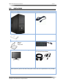
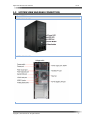
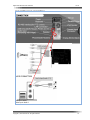
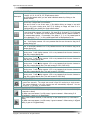
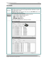
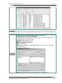
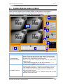
Digital Video Recorder User’s Manual Ver 9.x ABOUT THE CCTV SERVICES INC DVR SYSTEM Welcome to the CCTV SERVICES INC. Digital Video Surveillance System. Our DVR 9.x series features recording for Cash register Interface / POS devices. • Recording for up to eight Cash register / POS devices, system health status and configuration, multievent recording; continuous motion detection, alarm; and scheduled recording. • DVR 9.x series are a high-performance, Hybrid type PC-based, easy-to-operate DVR and client application system. • The DVR Server software runs on the DVR 9.x Series DVR. • The Client Application software runs on a personal computer (PC) and allows you to log on and operate the DVR 9.x Series DVR server system from your local PC. • Fully implemented networking capabilities allow remote administration, playback, and export using the accompanying client application. • Live viewing is supported on a variety of client platformㄴ Versatile high-speed search operations include time and date, event list. • Extensive scheduling features allow customizing of weekday, weekend, and special event recording. • CCTV SERVICES DVR 9.x DVR series provides a graphical user interface (GUI), allowing you quick and efficient access to all setup and operations functions. Scheduled or manual backup can be performed using a number of optical, external, and mapped network drive options. The CCTV SEVICES DVR series also supports the following PC-based applications: • CCTV SERVICES DVR Remote CLIENT (CMS/Remote Client S/W) • CCTV SERVICES DVR BACKUP S/W and VIEWER. COPYRIGHT © 2014 & TRADEMARKS The contents of this manual may not be copied or reproduced in any manner or form without the prior written consent of CCTV Services, Inc. ● CCTVSERVICES and DVR 9.0 Series (HS-08, HS-16, RT-16, HS-32) DVR systems are CCTV Services, Inc. Trademarks. ● Remote Client s/w (CMS(Central Monitoring Station) S/W) is a CCTV Services, Inc. Trademarks. ● CRI (Cash Register Interface) and DTVS (Data Transaction Verification System) s/w is a CCTV Services, Inc. Trademarks. IMPORTANT INFORMATION Before proceeding, please read and observe all instructions and warnings contained in this manual. Retain this manual with the original bill of sale for future reference and, if necessary, warranty service. When unpacking your digital recorder, check for missing or damaged items. If any item is missing, or if damage is evident, DO NOT INSTALL OR OPERATE THIS PRODUCT. Contact your dealer for assistance. WARNING TO REDUCE THE RISK OF FIRE OR ELECTRIC SHOCK, DO NOT EXPOSE THIS PRODUCT TO RAIN OR MOISTURE. DO NOT INSERT ANY METALLIC OBJECT THROUGH VENTILATION GRILLS. EXPLANATION OF GRAPHIC SYSMBOLS The lightning flash with arrowhead symbol, within an equilateral triangle, is intended to alert the user to the presence of un-insulated “dangerous voltage” within the product’s enclosure that may be of sufficient magnitude to constitute a risk of electric shock to persons. Copyright © CCTV Services Inc. All rights reserved. 1 Digital Video Recorder User’s Manual Ver 9.x The exclamation point within an equilateral triangle is intended to alert the user to the presence of important operating and maintenance (servicing) instruction in the literature accompanying the product. PRECAUTION SAFETY: Should any liquid or solid object fall into the cabinet, unplug the unit and have it checked by the qualified personnel before operating it any further. Unplug the unit from the wall outlet if it is not going to be used for several days or more. To disconnect the cord, pull it out by the plug. Never pull the cord itself. Allow adequate air circulation to prevent internal heat build-up. Do not place the unit on surfaces (rugs, blankets, etc.) or near materials (curtains, draperies) that may block the ventilation holes. INTALLATION: Do not install the unit in an extremely hot or humid area or in an area subject to excessive dust or mechanical vibration. The unit is not designed to be waterproof. Exposure to rain or water may damage the unit. CLEANNING: Clean the unit with a slightly damp soft cloth. Use a mild household detergent. Never use strong solvents such as thinners or benzene as they might damage the finish of the unit. IMPORTANT SAFETYGUARD READ INSTRUCTIONS – All the safety and operating instructions should be read before the appliance is operated. 1. ATTACHMENTS – Do not use attachments not recommended by the video monitor or equipment manufacturer as they may result in the risk of fire, electric shock or injury to persons. 2. POWER SOURCES – Video monitor or equipment should be operated only from the type of power source indicated on the marking label. If you are not sure of the type of power supplied to your home, consult your video monitor or equipment dealer or local power company. For video monitor or equipment designed to operate from battery power refer to the operating instructions. 3. POWER CORDS – Do not allow anything to rest on the power cord. Do not locate video monitor or equipment where persons walking on it will abuse the cord. 4. OBJECT AND LIQUID ENTRY - Never push objects of any kind into video monitor or equipment through openings as they may touch dangerous voltage points or short-out parts that could result in a fire or electric shock. Never spill liquid of any kind on the product. 5. SERVICING – Do not attempt to service video monitor or equipment yourself as opening or removing covers may expose you to dangerous voltage or other hazards. Refer all servicing to qualified service personnel. 6. DAMAGE REQUIRING SERVICE – Unplug video monitor or equipment from the wall outlet and refer servicing to qualified service personnel under the following conditions: - When the power-supply cord or the plug has been damaged. - If liquid has spilled, or objects have fallen into the video product. - If the video product has been exposed to rain or water. - If the video product does not operate normally by following the operating instructions, adjust only those controls that are covered by the operating instructions as an improper adjustment of other controls may result in damage and will often require extensive work by a qualified technician to restore the video product to its normal operation. 7. REPLACEMENT PARTS – When replacement parts are required, be sure the service technician has used replacement parts specified by the manufacturer or that have the same characteristics as the original part. Unauthorized substitutions may result in fire, electric shock or other hazards. Copyright © CCTV Services Inc. All rights reserved. 2 Digital Video Recorder User’s Manual Ver 9.x TABLE OF CONTENTS ABOUT CCTV SERVICES INC DVR SYSTEM. .................................................................................. 1 IMPORTANT INFORMATION. ............................................................................................................ 1 IMPORTANT SAFETYGUARD. .......................................................................................................... 2 DVR SYSTEM CONTENTS. ...................................................................................................... 3 CHAPTER 1. GETTING STARTED. .......................................................................................... 4 1.1. BASIC FEATURES................................................................................................................... 5 1.2 .UNPACKING........................................................................................................................... 6 1.3. SYSTEM VIEW AND REAR CONNECTION ................................................................................... 7 CHAPTER 2. USING THE DVR SYSTEM .................................................................................. 9 2.1. LOGIN DVR SYSTEM ........................................................................................................... 10 2.2. ENABLE WINDOWS FUNCTION KEYS. ..................................................................................... 10 2.3. DESCRIPTION OF THE DVR MAIN SCREEN ............................................................................. 11 2.4. LISTEN TO AUDIO. ................................................................................................................ 19 2.5. ADDITIONAL MAIN FUNCTIONS .............................................................................................. 19 CHAPTER 3.RETRIVAL OF RECORDED IMAGE ................................................................ .23 3.1. UNDERSTANDING SEARCH SCREEN. ...................................................................................... 24 3.2. RETRIVAL RECORDED IMAGE. ............................................................................................... 26 3.3. SMART SEARCH. ................................................................................................................. 29 3.3. ADVANCED SEARCH. ............................................................................................................ 32 3.4. ADDITIONAL FUNCTIONS. ...................................................................................................... 36 3.5. PERFORMING EXPORT(SAVE AS) . ......................................................................................... 41 CHAPTER 4. USING THE BACKUP SOFTWARE ................................................................. .45 4.1. MANUAL BACKUP. ................................................................................................................ 46 4.2. SCHEDULE BACKUP . ............................................................................................................ 47 4.3. CONCURRENT BACKUP . ...................................................................................................... 49 4.4. DIRECT BACKUP .................................................................................................................. 49 4.5. BACKUP VIEWER . ................................................................................................................ 51 FAQ. ........................................................................................................................................ 54 WARRENTY. ............................................................................................................................... 55 GROSSARY. ............................................................................................................................... 56 Copyright © CCTV Services Inc. All rights reserved. 3 Digital Video Recorder User’s Manual Ver 9.x GETTING STARTED Copyright © CCTV Services Inc. All rights reserved. 4 Digital Video Recorder User’s Manual Ver 9.x 1.1 BASIC FEATURES The Digital Video Recorder (DVR) is the core of the Digital Video Surveillance with Recording System for Security and manufactured by CCTV SERVICES INC. The DVR collects, saves, and plays back the digital video images in a fashion that significantly improves on the defects of existing analog CCTV. It implements a user friendly Graphical User Interface (GUI) complemented with very impressive features, making the CCTV SERVICES INC DVR the obvious choice. 1. 2. 3. 4. 5. 6. 7. Camera Input: Hybrid input - up to 16 channels of normal CCTV camera plus 4 IP cameras. Display Screens: 1, 4, 6, 9, 10, 16, 20, 25 and 36 camera split screens. Recorded Resolution: CIF, Half D1, D1, (CIF:352X240, Half D1:704x240, D1:704x480). Display Speed: 120fps, 240 fps, 480 fps (real-time) boards NTSC (frames per second). Users' easy change of Video Arrangement in Live Monitoring by Virtual Matrix·. Check and Control Camera and IP products status at Tree Menu. Outstanding Image Quality and Search Methods. The system provides various search conditions and an excellent image quality for searching an event or constantly saved data. 8. Efficient File System. The system stores data on baskets which are the disk space partitioned into certain areas. This file system efficiently aligns data and maximizes the speed of data processing. In addition, the stored data is effectively protected. 9. Convenient User Interface. The system allows users to operate it with simple mouse operation in a GUI environment for convenience, a VCR style playback control, and Gives the ability to retrieve information quickly. 10. Image printing: Saved image file can be printed with conventional Printers. 11. Archived Images can be backed up onto any back-up device for long-term storage. Video footage can be stored in 1 of 2 ways, using a Backup Viewer (Backup), or using the AVI format (save). 12. 16 Channels of Motion Detector functions. ● When motion detection occurs, the system immediately starts recording images onto the HDD. ● Recording interval and frame rate control during an event for optimized image saving. 13. Pre/post alarm recording function. ● Recording takes place 0-8 frames before and after and alarm event takes place. ● This ensures the entire event was recorded as well as recording lead-time up to the event. 14. Easy to use Search Function Timeline and Calendar. ● Makes finding the time and date of an event easy to locate. ● Gives a quick overview as to where and when activity took place. ● Index feature to book mark events for quick retrieval at a later time. ● Run and Search data of DVR (Analog) and IP as the same way. 15. Various Network Functions. The system provides the remote monitoring, recording, searching, sending, and controlling functions as well as the two-way voice communication through a network in real time. The transmission can also be enabled using a telephone modem and diverse networks. 16. One up to 16 Channel Audio record and playback at playback recorded image with co-working camera locally and remotely, two way audio operations. 17. Remote notification function (email, text transmission) and various type of alarms. (beep sound, moving line, enlarged screen, and email) 18. Remote viewing by either LAN for remote surveillance and remote management. 19. Analog outputs on Software Based Boards and 1 Analog output for hardware based boards, for spot monitors the can sequentially switch. 20. Multi-server so 1 business owner can watch up to 8 locations at one time Copyright © CCTV Services Inc. All rights reserved. 5 Digital Video Recorder User’s Manual 1.2 Ver 9.x UNPACKING DVR Set Configuration DVR system (1SET) System Power cable DVR User’s Manual Installation CD -Manual -Driver -Setup S/W Key Board / Mouse LCD Monitor(Size depend on order entry) Monitor connect cable /LCD monitor Power Adaptor Components can be changed according to option selection. Please unpack a system in flat and not wet place. Please check all components are in the package. Copyright © CCTV Services Inc. All rights reserved. 6 Digital Video Recorder User’s Manual 1.3 Ver 9.x SYSTEM VIEW AND REAR CONNECTION DVR SYSTEM View SYSTRM FRONT VIEW SYSTEM REAR PORT Copyright © CCTV Services Inc. All rights reserved. 7 Digital Video Recorder User’s Manual Ver 9.x DVR SYSTEM REAR CONNECTION AUDIO CONNECTION Red input: Audio 1 White input: Audio 2 Copyright © CCTV Services Inc. All rights reserved. 8 Digital Video Recorder User’s Manual Ver 9.x USING THE DVR SYSTEM Copyright © CCTV Services Inc. All rights reserved. 9 Digital Video Recorder User’s Manual Ver 9.x 2.1 LOGIN DVR SYSTEM To access the features of the CCTV Services Inc. DVR, each user must log in with a valid user name and password. User names and passwords are case sensitive. There are two user access levels that can be configured on the DVR. Access levels range from the Administrator, with the most rights and privileges, to the restricted user, with the least rights and privileges. For information about configuring access levels, refer to the User authority level section of the DVR user’s manual. For security reasons, you are prompted but not required to change the Admin password immediately after logging in for the first time. To log in with the Administrators account, do the following: LOCK button in the DVR Main screen, 1. When clicking on the Authentication Login prompt dialog will be appearing on the screen. (Shown below) Virtual K/B The built in Administrator user ID: admin, Password: 1111. (Use the keyboard or virtual computer keyboard, Clicking on the keyboard button to using virtual keyboard) 2. Enter admin in the User ID field and 1111 in the Password field. 3. Click on the OK button to log in. [NOTICE] Added default Administrator user ID and PASSWORD of our DVR is 195 or 393 for both. 2.2. ENABLE WINDOWS FUNCTION KEYS Enabling the Ctrl, Alt and Windows key allows you to open the Windows Task Manager Dialog box to perform Windows system administration tasks. To complete the procedure, you must be logged on to the DVR as an administrator on a DVR SYSTEM. FUNCTION key is locked, Ctrl, Alt, and Windows key not work. To enable the Ctrl, Alt and Windows key: 1. When clicking on the ALT and F2 key simultaneously on the Keyboard, ‘Close WinLock’ message dialog will be appearing. (Shown left) 2. Enable Ctrl, Alt, DEL and Windows key on the Keyboard. 3. Click on the OK button to close this message. Copyright © CCTV Services Inc. All rights reserved. 10 Digital Video Recorder User’s Manual Ver 9.x [NOTICE] When clicking on the Exit button to exit the DVR program, Shutdown message will be appearing on the Screen if not enabling Windows function keys. Normally, DVR SYSTEM will shutdown automatically when detecting physical disk problems (BAD sectors) or the DVR File System corrupted. (ImageDB) 2.3. DESCRIPTION OF THE DVR MAIN SCREEN DVR program starts automatically once the system powers up, the following Main screen appears after the system booting process. LOGGING IN TO DVR MAIN SCREEN LOGGING IN TO DVR To access the features of the CCTV SERVICES INC DVR, you must log in with a valid Description user name and password. LOCK is setup to prevent from unauthorized operation, For use front button and setup changes, you must unlock first. The built in Administrator user ID: admin, Password: 1111. Added default Administrator user, ID: 195, 393 / Password: 195. 393 User authentications prompt appear after clicking on the UNLOCK button, Fill in the ID, Password, and then click on the OK button to log in. To operate and configure all but the most basic features of the CCTV SERVICES DVR, you must be assigned an Administrator user account. User authentications prompt will be appearing when you access the below functions, Changing SETUP values / Independent SEARCH, PTZ control, Front SPLIT buttons, Additional FUNCTION buttons, Making initial file system (and adding HDD ) UNDERSTANDING THE MAIN SCREEN ABOUT THE MAIN SCREEN In the MAIN screen, users can control, monitor, manage all the video data like Description Screen Layout (Display Channel Split), video signal, sensor, relay, and live audio. Copyright © CCTV Services Inc. All rights reserved. 11 Digital Video Recorder User’s Manual Ver 9.x Live image View field Function button KEYLOCK, Setup, search, PTZ, Camera information and CAMERA Button Screen Layout (1~16ch:3120), (21,25: 2120), (36: 2432), Move Page, Full ,Auto TDS, Live Audio, Image Control and Manual Backup, DVR properties, log view, CD BURN button area Exit Company LOGO Live Audio, Client Connection Status FUNCTION BUTTON SEARCH button: This button is pressed to view images that were recorded onto the hard disk drive. Pressing the search button will open another program on top of the Freedom Systems live viewing so the cameras are still recording. PTZ button: This button is only for use with pan tilt zoom cameras. If your system has a PTZ camera select it in the main viewing area by either watching it in the 1 camera mode, or selecting it in any multi screen with the RED highlight. LOCK button: In order to use windows functions after starting the system, first enable (unlock) the windows function keys in the DVR system. MBACKUP button: This backup Button is pressed to backup important data that were recorded onto the HDD drive to your system partition area. (Detail refer to Chapter 4) Burning button: burning CD directly on the main screen. LOG Viewer button: This viewer file located at the DVR folder in the program folder. DVR system can built the system.log, event.log, Motion.log, Nework.log files in the Log folder in DVR folder at the operating. Properties button: checking system information Copyright © CCTV Services Inc. All rights reserved. 12 Digital Video Recorder User’s Manual Ver 9.x SCREEN SPLIT BUTTON Select split screen view by clicking screen division buttons. This will change the display to single, 4, 6, 9, 10, 16, 21, 25, 36 split screen views. Description On the single camera mode, you can select individual camera by clicking on the camera number. 1 CAMERA SCREEN: This Button will change the cameras in the main viewing area so there is only a single view of one camera. This can be done in one of two ways; 1) By double clicking an image in any multi screen in the main viewing area, and 2) by clicking an image one time so it is highlighted RED, then clicking the single camera select. 4 CAMERA SCREEN: This button will show 4 cameras in the main viewing area. It can show either cameras 1-4 (quad A), 5-8 (quad B), 9-12 (quad C), or 13-16(quad D) at one time. To select which 4 multi screen is viewed; click any camera number in the camera select section. For example, if the either 1, 2, 3, or 4 is pressed quad A will be displayed, if 5, 6, 7, or 8 is pressed quad B will be displayed and so on. 6 CAMERA SCREEN: This button will show 6 cameras at one time in the main viewing area. It will display cameras 1-6 or any cameras that the user chooses to drag into a camera display box. 9 CAMERA SCREEN: This button will show 9 cameras at one time in the main viewing area. It will display cameras 1-10 or any cameras that the user chooses to drag into a camera display box. 10 CAMERA SCREEN: This button will show 10 cameras at one time in the main viewing area. It will display cameras 1-10 or any cameras that the user chooses to drag into a camera display box 16 CAMERA SCREEN: This button will show 16 cameras at one time in the main viewing area. It will display cameras 1-16 or any cameras that the user chooses to drag into a camera display box. 21 CAMERA SCREEN: This button will show 21 cameras at one time in the main viewing area. It will display cameras 1-21 or any cameras that the user chooses to drag into a camera display box.(This multi screen for 2120, 2432 V8.0) 25 CAMERA SCREEN: This button will show 25 cameras at one time in the main viewing area. It will display cameras 1-25 or any cameras that the user chooses to drag into a camera display box.(This multi screen for 2432V8.0) 36 CAMERA SCREEN: This button will show 36 cameras at one time in the main viewing area. It will display cameras 1-36 or any cameras that the user chooses to drag into a camera display box.(This multi screen for 2432 V8.0) AUTO SEQUENCING BUTTON AUTO SEQUENCE: Pressing the Auto button will sequentially switch the camera views for preset time intervals. The single auto mode is used for monitoring a single screen. The camera displayed in the main viewing area will automatically sequence. You can do this for 1, 4, 6 and 9, 10 camera views. PREVIOUS & NEXT SCREEN BUTTON PREVIUOS: Show the PREVIOUS channel (in one channel) or previous screen division (in 4 channels or others) EX) When users see camera 2 on full screen, it goes to camera 1. When seeing 5~8 (Quad Mode), it goes to 1~4 (Quad Mode). NEXT: Show the NEXT channel (in one channel) or next screen division (in 4 channels or others) EX) When users see camera 1 on full screen, it goes to camera 2. When seeing 1~4(Quad Mode), it goes to 5~8(Quad Mode). Copyright © CCTV Services Inc. All rights reserved. 13 Digital Video Recorder User’s Manual Ver 9.x FULL SCREEN BUTTON: FULL SCREEN: This button will make the main viewing area the entire screen. In other words the entire computer monitor will display the cameras only. The toolbar buttons will not be displayed again until the left mouse button is clicked anywhere on the screen. Providing more screen area to display image. Double click anywhere on the screen to show previous screen with interface. Quick change from split screen to a single screen While on multiple screen view, double click LEFT mouse button on the desired Step1 camera to quickly change to SINGLE camera screen. When double-click the LEFT mouse button on the SINGLE camera Screen, it becomes Step2 to previous screen. Splits screen Double-Click the LEFT mouse button: Change to one Screen. One Screen Double-Click the LEFT mouse button: Return to previous splits Screen. VIRTUAL DISPLAY MATRIX Choose the one of screen first, and then the chosen screen can be moved to the location of the screen. Click and hold the left mouse button and then dreg the mouse pointer in the direction you want to move camera. Release the mouse button when you have repositioned the camera to the desired location. This does not influence the recording; it just changes the position shown in the Screen splits. It is Virtual Display Change. . Copyright © CCTV Services Inc. All rights reserved. 14 Digital Video Recorder User’s Manual Ver 9.x ADJUST COLOR ADJUST COLOR: This menu will allow you alter the individual characteristics of each camera. The lighting in the cameras view will change throughout the day, with the change of seasons, with changes in weather, and many other variances. These simple to use control bars ensure that your cameras are properly adjusted for your recording environment. When click on the ‘COLOR’ button, COLOR ADJUST button will be appearing in the screen. (Shown below). BRIGHTNESS: Up/Down, Adjust the Brightness Values of Video. CONTRAST: Up/Down, Adjust the Contrast Values of Video. SATURATION: Up/Down, Adjust the Saturation Values of Video. HUE: Up/Down, Adjust the Hue Values of Video. When users want to save this value, users can use this. When users want to apply this value to all channels, users can use this. When users wan to change all values to DEFAULT values. CAMERA STATUS LIST TREE Displays Top-down, hierarchical management of DVR cameras. It shows the attached CAMERA information, VIDEO LOSS status, and camera usage status. • CCTV CAMERA GREEN: Normal Camera signal. RED: Camera Signal Loss • IP Camera or Video Server GREEN: Normal Camera signal. RED: Disconnected from the Network (Video signal loss) YELLOW: Try to connect from the Network(still Video signal loss) On the single camera mode, you can select individual camera by clicking on the Camera number. Copyright © CCTV Services Inc. All rights reserved. 15 Digital Video Recorder User’s Manual Ver 9.x ON SCREEN DISPLAY(OSD) INFORMATION The OSD consists of camera Number, Description, Recording status, PTZ and Audio Instruction that is superimposed on each pane. ● CAMERA NO : Shows camera number in that channel ● Recording Status: [R] Recording, [C] Continuous Recording, [M]Motion Recording, [S] Sensor Recording, [C&E]Continuous & Event Recording, [S&M] Sensor & Motion Recording ● Camera Name (Description) : Shows the Name of each channel ● PTZ: When PTZ camera is connected and setup, [P] is shown. ● Audio: When Audio is connected, [A] is shown. Red Border Line : When Event is setup in each channel, it shows Red Border Line in that channel. DATE/TIME INDICATOR Date/Time/ Network Connection Information This shows the Data/Time information [Network Connection Icon] It show currently connected Client Status. Client connection status will be appearing after click on the CONNECTION INDICATOR (display it brightly) on the right area in time/date indicator. Display it Brightly when live audio running, PTZ CONTROL PANEL USING PTZ Description Users can operate PTZ cameras when entering this button. TIPS OF PTZ CONTROL Allows users with access rights to operate camera lens control features and to program PTZ presets, and tours. Users have to setup the PTZ on the DEVICE of SETUP dialog before using PTZ. Description According to PTZ control in DVR system, Do not setup the “ID=0” on to PTZ camera, DVR system not working at “ID=0” due to DVR system “ID=0” not available in PTZ Setting.(Camera 1 = PTZ ID 1) A tick inside the box indicates PT SET on the Camera Tab in SETUP. Setup (Refer to PT setting in Camera Tab) Click on the PTZ button. Open Panel PTZ PANEL BUTTON DESCRIPTION 1. Select channel No, just clicking on left / right(◄ ►) button. 2. Control using below buttons. Copyright © CCTV Services Inc. All rights reserved. 16 Digital Video Recorder User’s Manual Ver 9.x [Control Buttons] • POWER : Camera Power On/Off. • LAMP : Camera Light On/Off. • AUX : Auxiliary Power On/Off. • PTZ Direction Control Panel. • Auto-Pan : Auto PAN On/Off • PTZ Camera Selection. • Iris +/- Button. • Focus in/out Button. • Zoom in/out Button PTZ Panel • Speed up/down Button • PRESET Button. • PRESET Setup Button • TOUR button • TOUR SETUP button • Scan Group Button • Scan Group Setup Button PTZ PRESET Description A preset is a user-defined camera position using PTZ and focus commands the (camera’s auto focus option must be turned off). Only cameras that support positioning and programming using Pelco D, P, or supported third-party protocols can use this feature. ( Refer to Appendix) PROGRAMING A PRESET, do the following: 1. Click on the PTZ button after chosen CAMERA CHANNEL. 2. Click on the button in the PRESET field on PTZ Panel. Preset dialog appearing, Programing PTZ Preset click on the ADD button 3. Move the camera to wanted place 4. Preset ADD dialog appearing.(Shown above) fill in Preset No and Description. 5. Click on the ADD button to activate preset and Exit button, Activated Preset NO will be listed on the Preset list field in Preset dialog. When you program the same Preset No, the last No is saved. 6. Users can add presets making same progress. (3~5). Copyright © CCTV Services Inc. All rights reserved. 17 Digital Video Recorder User’s Manual Ver 9.x 7. Have to save programmed Preset, just click on the SAVE button. 8. Click Exit button to exit programming mode in the Preset dialog. START PRESET 1. Choose the activated Preset position in the Preset list field. PRESET RUN button to testing Preset position, will be Move the Click on the camera according to activated preset position. PRESET TOUR Description A preset tour allows a camera to move through a programmed sequence of PTZ presets. The DVR-2000 or DVR-3000 Series DVR can store up to four preset tours. At least one PTZ preset must be set in order to create a preset tour. PROGRAMING PRESET TOUR SETUP the several PRESET position first, and then Click on the on the Touring area in PTZ Panel. The “Tour” dialog box opens. (Shown next page) To Programming Preset Tour, do the following: SETTINIG button Programing Preset and Tour a. Tour ADD dialog appearing after click on the ADD button to add presets to a tour on the Tour dialog. (Shown left) b. Fill in TOUR NO and DESCRIPTION. c. Select and Add Preset in list by clicking on the button and then define the Duration Time of touring. Chosen preset will be move on to Tour Member field. Touring programming need several Touring just making the same progress. When set this as 2, the preset Dwelling time is set as 5 seconds. If need check camera position, just double clicking, it starts testing of touring. d. Click on the ADD button to activate preset tour and Exit button to return to the Tour dialog. e. Activated Preset tour will be listed on the Tour list field in Tour dialog. f. Have to save programmed Preset, just click on the SAVE button. g. Click on the Exit to close programming tour. Copyright © CCTV Services Inc. All rights reserved. 18 Digital Video Recorder User’s Manual Ver 9.x START TOURING Choose the listed Tour on the Tour list field in PTZ panel. tour run button to starts touring, , will be moving the camera Click on the according to programmed tour. When users use PTZ and Dome camera with Preset Receiver, however, when using several PTZ cameras at the same time, users can not use Touring. This is because our Touring is done by S/W [NOTICE] Please check again below if users can not get right movement after checking the movement exactly. a. Selected PTZ camera is in the List to support or not. b. Right Protocol. c. PTZ camera H/W connection. d. Power. 2.4. LISTEN TO AUDIO LISTEN TO LIVE AUDIO Give the instruction to get Live Sound with live viewing in the Main Screen. Description To listen to Live Sound, first users have to setup. Select the Camera channel and Click on the AUDIO button in the Main Screen. Step1 Live Audio control dialog will appear on the screen. (Shown next page. Step2 When click on the Play button, will be listening to audio after Play button changes to Stop button. Click on the STOP button to stop if you need to stop audio. Users can see available channel with Audio which is setup in each channel Step3 Step4 If you need volume up or down, clicking on down, up button. To change gain value, users have to use Microphone directly in the monitored place( gain ‘0’ means No Compensation in Sound) Click on the AUDIO button again to closing the AUDIO listening function. 2.5 ADDITIONAL MAIN FUNCTIONS FUNCTION IN OTHER BUTTON FIELD This area functions are easy use at the main screen, PROPERTICES / MANUAL BACKUP / LOG VIEW / CD BURN Copyright © CCTV Services Inc. All rights reserved. 19 Digital Video Recorder User’s Manual Ver 9.x SYSTEM PROPERTIES SYSTEM PROPERTIES BUTTON PROPERTIES button: DVR system information display. System information will be appearing after click on the PRORPERTIES button in the DVR Main Screen. (Shown next page) WRITE TO SAVE button for copy this file for ‘System information’ checking ‘systeminfo ‘file is saved in C:\program files\dvr (shown ‘ex’ below) [NOTICE] Please check this syseminfo file if DVR system failed to function or halt. All of DVR system transaction is saved on this file. Copyright © CCTV Services Inc. All rights reserved. 20 Digital Video Recorder User’s Manual Ver 9.x LOG VIEWER USING Log View LOG VIEW button is pressed to view DVR system log files. DVR system creates the Log files on the program files folder / DVR folder / Log folder Description during DVR program running. LOGVIEWER dialog will be appearing after click on the LOG VIEW button on the OTHER button field. (Shown below) How to viewing log files, do the following: 1. Choose the log view start date and time, END date and time. 2. Choose the Search field: Main, Event, Network. MAIN : SYSTEM / CAMERA / ERROR EVENT : MOTION / SENSOR NETWORK : CONNECT / NOTIFY 3. Click on the SEARCH button. Searching Start, and appearing the checked log information. (Main Log: Shown below) (EVENT Log: Shown below) (NETWORK Log: Shown next page) Copyright © CCTV Services Inc. All rights reserved. 21 Digital Video Recorder User’s Manual Ver 9.x CD BURN USING CD BURNER CD BURN button for CD burning directly on the DVR main screen. (To burn CD, have to save files onto HDD) CD BURN Dialog will be appearing in the screen, when click on the CD BURN button in the OTHER button field. (Shown below). Add Folder: Adding folder on the CD. Add File: Select the data for burning. RESET: Clear added files or folder. WRITE: Start Burning. ERASE: Delete the data in CD-RW,DVD-RW media, Use this button If not want to burning selected data. EXIT: closing CD burn dialog. Notice: Check the file size to burn in CD before Burn in CD and burn. Copyright © CCTV Services Inc. All rights reserved. 22 Digital Video Recorder User’s Manual Ver 9.x RETRIEVAL RECORDED DATA Copyright © CCTV Services Inc. All rights reserved. 23 Digital Video Recorder User’s Manual 3-1 Ver 9.x UNDERSTANDING SEARCH SCREEN Enters the search mode and opens the Search SCREEN, providing access to search features. When click on the SEARCH button in the Viewing Main Screen, Search screen will appear. (Shown below) The name and function of each button are described below. 4 7 10 6 9 5 8 1 3 2 11 INTRODUCE SEARCH MAIN SCREEN The calendar is how the date you wish to view is selected. The days that are YELLOW, are days that have video footage. The days that are WHITE are days without any video footage. The arrows on the sides of 1. Recorded data the month are to select different months and years. Information Calendar *Note: The single arrow changes the month and the double arrow changes the year. If a date contains recorded data, the date will be displayed YELLOW, No Recorded Data: WHITE, Current Date: RED The Timeline Table gives a brief overview as to where motion was recorded throughout the day. The green lines correspond to what time of day footage was recorded. In order to locate the footage you are trying to find, simply click on the green line that corresponds to the 2. Playback Time Line appropriate camera and time. * Notice that every green line is for a different camera and the clock represents military time format. Copyright © CCTV Services Inc. All rights reserved. 24 Digital Video Recorder User’s Manual Ver 9.x [Color for each Recorded Mode] White: No Data 3. CAMERA SCROLL and Camera Label 4. Information Window 5. Playback Control Panel 6. SPLITS, PANORAMA, ZOOM, FULL button 7. FUNCTIOIN Buttons 8. Book Mark, GoTo Buttons 9. SELECT SOURCE Button 10. Image display Window 11. Exit button ██ Green: Continuous Recorded Data ██ Yellow: Motion Recorded Data ██ Orange: Sensor Recorded Data ██ Blue: Continuous & Event Recorded Data ██ Pink: Sensor & Motion Recorded Data Each Dark Color means Recorded with Audio This scroll bar and Camera label will show the other cameras on the system. Click and hold the tab, then drag up and down to show the remainder of the cameras. It shows the information of recorded data. Time/Date/File Size/Recording Mode The play button will begin the playing of the video from where you have selected on the camera time line. Forward Play, reverse play, forward Play by Frame, revere Play by frame, peed up/down, Stop, Audio play SINGLE button: The single icon is for reviewing only one camera at a time. MULTI button (4/9/16): gives you the ability to view 4, 9, or 16 cameras in playback at the same time. Click the each button to playback 4 cameras, 9 cameras, 16 cameras. Note: The camera in the top left corner will be the first camera selected. The subsequent cameras will automatically fill-in in numerical order. PANORAMA: Panorama button is a playback feature that shows the motion of a single camera in nine individual frames, one frame at a time. To use this feature, click panorama button, then play. Note: You can also change the playback speed when using this feature. ZOOM: Specific areas may be selectively “zoomed” by holding the rightclick of the mouse, and dragging it to create a red box, will effectively magnify the red box to the full screen Print, Save, Smart Search, Image Color Adjust Tool Can Book marking certain recorded data. Goto Camera No, Recorded date and Time. Select the Storage drive of recorded data. Update all recorded image and reload If you double the click the picture, the size will increase. You can continue to double click the picture until you reach its maximum size. EXIT: The EXIT button will take you back to live viewing mode. The DVR will continue recording while you are searching recorded images in the Search mode. Copyright © CCTV Services Inc. All rights reserved. 25 Digital Video Recorder User’s Manual 3-2 Ver 9.x RETRIEVAL RECORDED DATA Description Recorded video can be played back one channel at a time on the screen. Like live video, recorded video is viewed from the camera view window on the screen. When click on the SEARCH button in the DVR main screen, The Search Main screen will appear on to screen. (Shown below) To Retrieval Recorded data, do the following: a. Choose the Existing Recorded data information indicated on the Calendar. b. Recorded data time information appears on the Status Time Line Table. Names of each camera are displayed in the CAM1 - CAM16 areas on the status Time table. c. Click on the Up/Down button on the left side, and choose the camera you wish to view. d. Click on the Time Line in the playback Time Line. The Yellow color Changes to RED color in the chosen hour area in the Playback Time Line e. Display the recorded image data on to screen according to chosen hour on the Time Table. Copyright © CCTV Services Inc. All rights reserved. 26 Digital Video Recorder User’s Manual f. Ver 9.x Click on the Play button to playback in the Play button panel, play back the video on the window. (Shown below) The above Picture show the data when click on the Yellow date. Hour/Minute Table In Hour zone, Red Line is shown by 3 hours for easy checking, and In Min zone, Red Line is shown by 5 minutes as well. To change from Hour to Minute: Hour to Minute: Double-clicking right mouse on the Hour playback time line to change from hour intervals to minute intervals. Minute to Hour: Double-clicking right mouse on the minute playback time line to change from minute intervals to hour intervals. Copyright © CCTV Services Inc. All rights reserved. 27 Digital Video Recorder User’s Manual Ver 9.x 1. Cameral Move (Up/Down button) 2. Select camera name or NO 3. Search Pointer Cameras are Grouped 4, users move to next Group just click on 1. Camera Move the Up/Down Button. 2. Select camera name or NO It point out the current SEARCH Hour / Min. 3. Search Pointer It point out the current SEARCH Hour / Min. PLAYBACK PANEL PLAY button: The play button will begin the playing of the video from where you have selected on the camera timeline. REVERSE PLAY button: This button is to play the video footage in reverse STOP button: Clicking the stop button stops the footage AND brings the timeline back to where the video was started. For example, if you start playing at 4 PM and click stop when the timeline hits 5 PM; the red timeline bar will return to 4 PM. SPEED DOWN button: When Clicking button, the footage will play slower down from faster play. Speed Down Button, the PLAY goes slower down to 2/4/8 times after Speed Up max maximum 8X. SPEED UP button: When Clicking button, the footage will play faster first click 2x up, next click 4x up, next click 8x up from normal play. (R,x2,x4,x8). PREVIOUS PLAY button: This button allows you to manually view frame by frame backward. To use this feature you must click the icon every time you want to change the frame 1 frame down NEXT PLAY button: This button will allow you to view the recorded data one frame at a time. In order to use this feature, you must click this icon every time you want to move one frame forward Sound play button at a playback the recorded image data INFORMATION WINDOW This shows the Y/M/D and H/M/S of recorded Data in searching, and Camera Name, Recorded Mode as well. Normal(R) Continuous REC Normal & Event Motion(R) Sensor(R) Motion REC Sensor REC Sensor & Motion Copyright © CCTV Services Inc. All rights reserved. Continuous & Event REC Sensor & Motion REC 28 Digital Video Recorder User’s Manual 3-3 Ver 9.x SMART SEARCH THUMBNAIL SEARCH Description Step1 Thumbnail search is a function that helps users to find the videos, they are look for more easily by showing every hour’s stop To access the Motion Detection you will need to open the search feature. Once in the search feature the user will need to click on the SMART SEARCH button. To go Thumbnail search, do the following Step2 Select the Thumbnail search after click on Smart Search button, Thumbnail search screen will be appears(below screen) 1 Step3 2 3 Item (1) (2) (3) (4) (5) Copyright © CCTV Services Inc. All rights reserved. 4 5 Description Search and enlarge thumbnail videos Shows thumbnail videos Shows the fist videos in the selected time. When choosing the video it shows every 10 min’s videos. (Hour=>10min=>1min=>10seconds) Playback button for selected some nail images area. Selected image for book mark or save 29 Digital Video Recorder User’s Manual Ver 9.x MOTION SEARCH Description The advanced Smart Search feature is a new addition to the CCTV SERVICES INC DVR that allows a user to find a certain event of any camera at anytime by utilizing the built in smart search feature. There are two parts to this new function. The first part allows the user to define specific areas of a cameras recording and the software will analyze the footage for the time specified. They will then be able to review any motion that went on in those specific areas the user has defined. To do this, the following screenshots will assist you. To access the Motion Detection you will need to open the search feature. Once in the search feature the user will need to click on the button. 1) Step 1 SMART SEARCH Once you have entered into SMART Search, you will be in the Motion Detection portion of the search. From this screen, you can choose the time you want to search for motion by selecting the Date, the Start Time and End Time in chosen camera from which camera you would like watch. First, you will need to select the date from the top right that you would like. Once the date has been selected you will need to select the time. To do this, use your left mouse button and click the up and down areas by the corresponding hour and minute to determine the exact time you would like to search for chosen camera. Once you have selected the date, time you will continue to the next step. Step2 Now that you have all your corresponding times, time and date selected we need to proceed and draw boxes around the areas that we would like to search for. Copyright © CCTV Services Inc. All rights reserved. 30 Digital Video Recorder User’s Manual Ver 9.x By holding down the left mouse button on the camera view, you draw a box over the area that would like to choose from. Once the area is chosen, a green box will appear from where you did the drawing over the picture. The following picture will show what you will be seeing. Step2 Now that the area is selected, The picture above will show what you have just done. Next Click on the SEARCH button to start search after chosen Search area and adjusted sensitivity. You will now see a detailed list of every time an object passed through the RED box. Step 3 Step3 Search finished message appear after finished search. PLAYBACK FROM MOTION EVENT LIST Playback Searched image from bookmark, do the following: 1. Select the one of list in the Motion checking list field. 2. Click on the ADD button to Bookmark, chosen list will be added on the book mark list field. 3. Click on the chosen list on the Motion selection field. 4. Click Play button on the Smart search dialog. 5. Start the playback video after appearing search screen. When clicking the motion event list, video playback message will be shown and can play. Copyright © CCTV Services Inc. All rights reserved. 31 Digital Video Recorder User’s Manual Ver 9.x 1. Choose the one of date in the list field. 2. Click on the Add button to bookmark on to Motion Selection field. 3. Choose the listed one of bookmark in the Motion Selection field. 4. Just click on the chosen list, and then click on the Play button to playback. If you need to Print or save JPG file, Click on Print button or JPG save button on the Play area in Smart search dialog. 3-4 ADVANCED SEARCH QUICK SEARCH Quick Search made for easy and quick search on the Main Screen w/o entering Search when users need urgent search. To Search and Playback video using the Quick Search, do the following: a. Click Right mouse button on the chosen camera channel. Description b. Will be appearing playback drop down menu. (Shown below) c. oose the time range to playback on drop down menu and click on the chosen time range. The chosen time zone will playback on the Quick Playback screen instantly. d. Click speed up button if you need to speed up. Copyright © CCTV Services Inc. All rights reserved. 32 Digital Video Recorder User’s Manual Ver 9.x Adjust Playback Speed Not exist data message will appear if recorded data does not exist.(Shown left) If you need playback in others time zone, do the following: a. Double clicking on chosen year, date and hour. (Shown below) b. Minute drop down menu will be appearing. c. Choose the minute time range to playback on drop down menu d. The recorded image data will playback on the screen e. Click on EXIT button to close Quick search after the stop playback. MULTPLE SPLIT PLAYBACK Description Users can search and playback multi-channel data MULTI button (4/9/16) gives you the ability to view 4, 9, or 16 cameras in playback at the same time. Click the each button to playback 4 cameras, 9 cameras, 16 cameras. Click on the PLAY button after chosen Splits button. (4/9/16). Multiple modes will be playback. Copyright © CCTV Services Inc. All rights reserved. 33 Digital Video Recorder User’s Manual Ver 9.x PANORAMA PLAYBACK Description Step1 Step2 PANORAMA a playback feature that shows the motion of a single camera in 4’ 9, or 16 individual frames, one frame at a time. To use this feature, Step 1~5 is the same as one channel SEARCH. (To do the same thing to Hour/Min Zone Search) Click on the PANORAMA button. Click on the PLAY button to Panorama Play back. (Shown below) Panorama Search GOTO(TIME SEARCH) Description The GOTO button will go to the playing position of the video from where you have selected camera, recorded date and time. To access the GOTO, you will need to open the search feature. Once in the search feature the user will need to click on the GOTO button. Step1 Copyright © CCTV Services Inc. All rights reserved. 34 Digital Video Recorder User’s Manual Ver 9.x Will be appears Select time dialog(Shown below) Fill in the Channel(camera no), Date and time and Click “OK” go to image location directly and image will be display on to screen. Step2 FULL SCREEN PLAYBACK Description FULL SCREEN button FULL SCREEN playback feature that display full screen image when playback the one splits mode. FULL: The full button will make the recorded video play in full screen. Once you are done watching in full screen you must click the to the regular search method. Copyright © CCTV Services Inc. All rights reserved. FULL screen button again to return 35 Digital Video Recorder User’s Manual Ver 9.x AUDIO PLAYBACK AUDIO PLAY AT THE RETRIEVAL IMAGE a. Click on the Audio button when playback recorded image data. b. Play the recorded image with AUDIO. SEARCH IP CAMERA RECORDED DATA EASY FIND OUT IP CAMERA DATA Description To easy search for IP products data (recorded data in file system). Default location is ANALOG when click Search button, Click on the IP Camera button in the Search window screen. Recorded data time line will be appearing on the Playback Time Line with existing IP camera name. Next step same as search progress. CH Selection for Analog and IP Cameras(IP product CH is saved in 33, 34, 35, 36 CH) 3-5 ADITIONAL FUNCTIONS PARTIAL ZOOMING Description To search wanted images easily by searching in <Enlarged> images. N.B This function is very useful in searching and finding wanted images or movement in big place. Step 1~3 is the same as 1ch Search.(To do the same thing to Hour/Min Zone Search) Click on the Partial ZOOM button. Copyright © CCTV Services Inc. All rights reserved. 36 Digital Video Recorder User’s Manual Ver 9.x Step 1 Will be appearing the zoom window.(see left) Select Enlarged area in the image and Draw the Square like left Picture at zoom window.. Selected square image will be enlarged. Step 2 Copyright © CCTV Services Inc. All rights reserved. 37 Digital Video Recorder User’s Manual Ver 9.x Another zooming by COLOR Adjust panel, COLOR Adjust panel appears on the screen after click Adjustment Button on the on the Search main window. (Shown below) ZOOM IN/OUT On single display, left button double-click on mouse may be used to magnify the image. An image may be magnified no more than three times. (x1, x1.5, x2) Description If recorded data are high resolution (704x480 or 720x480), zoom up function not working. Zoom up only for quarter size (352x240(CIF) resolution) recorded data. Double click the left button mouse to 1.5X, again Double click to 2X, Double click to 1 X. BOOKMARK Description Step1 The Search allows you to bookmark a video region for one camera and apply that book marked time window to multiple. This feature is used in conjunction with the export feature. Step 1~5 is the same as 1ch Search.(To do the same thing to Hour/Min Zone Search) Locate the timeline at the book mark point you want to bookmark. Step2 To create book mark, do the following: Step3 a. b. c. d. Copyright © CCTV Services Inc. All rights reserved. Index button. Click on the Add book mark dialog appearing. Fill in information and comment, and the click on the OK button. Book marked date and time will be added on the book mark list field. 38 Digital Video Recorder User’s Manual Ver 9.x Click on the Exit button to close book mark. ON SCREEN BOOK MARK Just click RIGHT button mouse on the chosen image. Bookmark drop down menu will be appearing on to screen. On screen (Shown left) Enter simple description to Identify Bookmark, and click on the OK button. When click on the (Shown below) List button, bookmark list will be appearing. Bookmark list Auto is book marked at the Smart Search. Manual is book marked by book mark button. If need show image on book marked position, Just clicking on the chosen book mark, display the recorded image on to search screen according bookmarked position. PRINT Description Step1 Step2 To print the searched image. The image Size depends on Resolution Comment dialog will be appearing after click on the button. (Shown below) PRINT dialog will be appear after fill in Descriptions of printed image, then Click on the OK button.(Shown below) Copyright © CCTV Services Inc. All rights reserved. PRINT 39 Digital Video Recorder User’s Manual Ver 9.x Click on the PRINT button on the print dialog after confirming the image and description Step3 Information of Printed Image 1. Signature: Guaranteed DVR Image. 2. Name and ID of the camera. 3. Site installed, owner, site information. 4. Recorded time: Time recorded by the system. 5. Printed time: Time the image is printed.. 6. Computer User Name. 7. OS and Serial NO. 8. Video Image. 9. Comments. ADJUSTMENT COLOR Description This feature will allow you to adjust the brightness, contrast and HUE of an individual still frame. The changes you make will not carry over to the entire video. It is only for the one still frame you are viewing. ‘Adjustment’ button on the Search Main Click on the screen for adjusting playback image. Brightness : Brightness compensation Contrast : Contrast correction HUE : Color Value Compensation Sharpness : Sharpness/Undo Blur : Blur GRAY : White/Black Change: Undo, Exit Original : Go to original data UNDO : Cancel : Exit Copyright © CCTV Services Inc. All rights reserved. 40 Digital Video Recorder User’s Manual Ver 9.x USING SELECT SOURCE BUTTON Description Updating all recorded image and reload, To easy go to recorded data location Default data from file DB in Local System at a running Search. If you need to update all recorded image and reload or searching recorded data from other location of file DB, click on the SELECT SOURCE button on the Search screen. Select source drop down menu will be appearing on the screen. Click local System data tab for updating all recorded image, will be updating all recorded image and reload. To Search recorded data by Source button, do the following: A. Choose the one of source data location type. B. Browse for Folder dialog will be appearing on the screen. C. Choose the location of data Disk with folder name, default folder is ‘_Backup. D. Click on the OK button to close Browse for Folder dialog on the dialog. E. Existing recorded data information appearing on the Calendar. (YELLOW color) F. Following step same as SEARCH and PLAYBACK progress. 3-6 PERFORMING THE EXPORT STILL IMAGE(JPEG) FORMAT Description Save current image as a bmp or JPEG format to a diskette or destination Drive DISK (including external USB Drive. DVR System can Save a images onto the HDD or FDD, USD HDD, USB stick. Saved JPG format type files have a Watermarking feature. Step1 Step 2 Step3 SAVE AS JPEG or SAVE AS AVI will be appear on to drop down menu after clicking on SAVE button. (Shown below). Clicking on the SAVE as JPEG in the drop down menu Click on the SAVE button after choose the DISK DRIVE and SAVE Folder. Copyright © CCTV Services Inc. All rights reserved. 41 Digital Video Recorder User’s Manual Ver 9.x (File name is made automatically, but can be changed as user wants.) A tick inside the round indicates JPEG, and then will save the image on to chosen Folder of Drive after click on the OK button. Step4 JPEG file copied message will appear after the copy is done. AVI VIDEO FORMAT Description Save is a way that you can save video the footage to hard drive so it will not be overwritten. You can then save the footage on to a compact disc, or save still images of a particular camera to a floppy disk or compact disk. To save a full motion video file follow the same step, but in the Save as type in drop down box, choose the Save as AVI. To the save as AVI, do the following: a. Click on the SAVE button on the SEARCH Window screen. b. Choose the Save as AVI on the drop down menu.(Shown below) c. AVI backup dialog will appear. (Shown below) d. Choose the Camera Channel. e. Set Start Time and Set End Time. f. Click on the AUDIO RECORDING for Audio record with image. In the motion recording, audio synchronization with video automatically. Audio Synchronization cannot be perfect. g. Choose the Media to save, if you need the folder name, fill in the folder name. Copyright © CCTV Services Inc. All rights reserved. 42 Digital Video Recorder User’s Manual Ver 9.x Click on the Start Recording button, AVI format creating will starting. Progress rate bar will appear after clicking on the START RECORDING button, AVI file (full motion video clip) will save to the chosen folder. [NOTICE] Audio Synchronization Function. Audio synchronization with Video is done automatically. But this is done when at least 1 fps is saved,. So users have to save at least 1 fps. So in Motion recording, Audio Synchronization cannot be perfect. Exit program dialog will be appearing after click on the EXIT button in the AVI Backup dialog. (Shown below) Click on the YES button to exit Save as AVI. Copyright © CCTV Services Inc. All rights reserved. 43 Digital Video Recorder User’s Manual Ver 9.x [NOTICE] Backup Media 1.Default: Backup in the root, C:\_backup in Local HDD(Can be used again) CD/DVD: CD R/RW,DVD R/RW 2. External: Backup in USB external HDD or other external storage. When users named the folder, all backup files are saved in the <time/date> folder when backup. In this <time/date> folder, all backup data are saved as <time/date>.file. 3. When users did not name the folder , <time/date> folder is made and in this all data are saved , all backup data are saved as <time/date>.file. AVI File Play Using Window Media Player, users can play backup AVI File just double-clicking when WMP is installed in the system. SAVED FOLDER MANAGEMENT To management saved AVI files in backup media, which is very useful to AVI Description playback. Management dialog will be appearing after click MANAGEMENT button. (Shown next page Saved AVI backup data save on to others Media or folder and delete it on this dialog. Also display the available backup media space. Click on the Exit button to close management dialog. CD/DVD SETUP Specify CD/DVD media, use or not save on to selected media at the AVI backup. Description Select used CD/DVD device. A tick inside the box indicates Save in Disk, when you chosen media Device. Click on the Save button to close. Copyright © CCTV Services Inc. All rights reserved. 44 Digital Video Recorder User’s Manual Ver 9.x USING THE BACKUP S/W Copyright © CCTV Services Inc. All rights reserved. 45 Digital Video Recorder User’s Manual Ver 9.x There are 4 kinds of Backup for Manual, Schedule, Concurrent and Direct backup. Moreover users can backup all data file directly just identifying the Backup Date. 4-1 MANUAL BACKUP Users can use this to backup the data recorded in specific camera, time, and minute period with Audio. It is recommended to backup the selected data (based on time, min, or specific filtered) Available Media: HDD, DVD, DAT, CD-R/W, External USB HDD, Network Drive When using some Backup devices, users have to use specific S.W which is supported by a device, in this case users have to install this S.W in the system. More users have to format this media first(CD-R, CD-R/W, DVD) before backup Description First Click on the LOG,BURN button in the Main screen. Backup button on the other function field. Next, click on the Manual backup dialog will be appear below as, Step1 (Backup Dialog) . Copyright © CCTV Services Inc. All rights reserved. 46 Digital Video Recorder User’s Manual Ver 9.x To Manual Backup, do the following: a. Chose the Camera Channel. b. Choose the Time: Set Start Time and End Time. c. Choose the Media to Backup: Default is ‘_Backup Folder’ in Drive C. Backup Folder in Drive C/ CD,DVR Drive / Other External Media(USB HDD etc) d. Fill in the folder name on to folder name area. Message dialog appear (Shown below) if not fill in folder name. e. Backup will be progress after click on the START BACKUP button. Step2 Backup Done message dialog appear after backup done , Will be return to Manual backup main dialog after click on the OK button on backup done dialog.(shown above) Click on the EXIT button to closing Manual backup. 4-2 SCHEDULE BACKUP Description Set up Schedule Backup Users can make automatic backup using Schedule Backup to backup the data in setup date/time for selected data. When backup Drive space is not enough to save all selected data, Not Enough Space message will be shown. ※Users can not use Schedule Backup and Concurrent Backup at the same time. To run Automatic Backup, Start Schedule Backup has to be active status.(Please check the Icon in Tray Bar) When System starts, Schedule Backup runs by DVRLoader automatically. Click right button Mouse on the Schedule icon in the bottom right of Windows screen. Schedule backup sub drop down menu will be appearing. (Shown below) Copyright © CCTV Services Inc. All rights reserved. 47 Digital Video Recorder User’s Manual Ver 9.x SCHEDULE BACKUP dialog will be appearing when chosen BACKUP SCHEDULE SETUP in the drop down menu. (Shown below). [Automatic Backup Type] 1. Schedule Backup (Selected Period Backup) 2.Concurrent Backup SELECT BACKUP TIME(Including Full Backup ) Step1 A tick inside the box indicates Schedule Backup enabled. 1) Click on the Select button and select Backup Drive. 2) A tick inside the box indicates Use Auto Deletion if need it. Step2 Auto Deletion is auto-delete the oldest data when selected Drive HDD space is full, and overwrites data. Choose the Backup Type. Full Backup(24 hours) Selected Specification Time Backup (Backup the data from Start to End Time) Step3 Step4 (In Full Backup) Step5 Step6 Choose the Start Backup Time. (Start Time for Schedule Backup is done for the first time) Choose the Start Date. (From the data of this time, data is Backup automatically) Click on the OK button to exit. When Backup is done by Schedule Backup, users can see this by Backup Viewer. Copyright © CCTV Services Inc. All rights reserved. 48 Digital Video Recorder User’s Manual Ver 9.x 4-3 CONCURRENT BACKUP Description To use Concurrent backup, Schedule Backup(including Full Backup ), users are recommended to use Big Size HDD after calculation of selected data Size. This is done by once in a day. Concurrent Backup is the system to backup the data at the same time when data is saved in HDD. Briefly speaking, our system saves the recorded data in selected HDD Drive (normally in D:) as ImageDB, so when users use Concurrent Backup, users can backup this recorded data in selected HDD drive at the same time as ImageDB. 1. A tick inside the box indicates Concurrent Backup enabled. Instruction 2. Click on the Select button and select Backup Drive. 3. A tick inside the box indicates □ Overwrite for overwriting after full in Backup Disk 4. After click on the OK button to exit, it automatically starts Concurrent Backup. With Backup Viewer, users can see backup data. 4-4 DIRECT BACKUP Direct Backup Description Users can backup the data at the same speed as PC Copy Speed, However, users can not search for the data before Backup. Drop down menu will be appear (shown left) after click the RIGHT button mouse on the schedule Backup running Icon. Instruction Copyright © CCTV Services Inc. All rights reserved. Next click on the DIRECT BACKUP tab after chosen it. 49 Digital Video Recorder User’s Manual Ver 9.x Click on the Backup button on the Recorded data Tie Dialog. (Shown left) after chosen date. YMD/Record Start Time ~ YMD/Record End Time for all channels. So users can backup all the data based on this information. Step1 Shift(Select All), Ctrl(Select several data) Step2 Backup will be starting, chosen data backup on to default data save folder. Backup done message will be appear after Backup completely. Step3 Please check the backup folder (Ex, 20061017) in saved folder. Users can see this by Backup Viewer. Manual Data File Backup (Files Copy) Please be careful in using this Backup, it is recommended that Expert or Manager uses this in urgent case like HDD problems. It is very similar like Direct Backup, but the only difference is to backup manually ImageDB. Description [Please use this in below cases] HDD problems! Users have to replace systems when some systems have a problem, and have to backup HDD in troubled system. Manager needs this. Copyright © CCTV Services Inc. All rights reserved. 50 Digital Video Recorder User’s Manual Ver 9.x Instruction 1. Open Window Explorer 2. Search DVR folder in ImageDB made directory. 3. Choose the Files to copy in IMAGEDB folder. 4. With Shift, Ctrl key (like Window), or Drag & Drop, users can select the files easily to copy. Have to select Image file and index together as a couple (Ex, WS000017 / WS000017.idx ) 4. Copy them to …. (Please copy this not <move>) Users can see backup data with Backup Viewer. 4-5 BACKUP VIEWER Description Use Backup Viewer when monitor and see AVI Backup, Manual Backup, Schedule Backup, Direct Backup, and Files Copy by Manual. Window Media Player can be used in AVI backup playing as well. Run 1)Start > Program > DVR >Backup View. Run 2) Run Backup Viewer directly. C:\Program Files\DVR\BackupView.exe …Just Double-Click [NOTICE] If not installed Backup view s/w, Please install first before using backup view. Backup view s/w is one of viewer s/w Instruction Click on Select Source button for search and playback the Backup data from Backup Disk Copyright © CCTV Services Inc. All rights reserved. 51 Digital Video Recorder User’s Manual Ver 9.x Users have to search and designate the Backup folder exactly. When finding, click on the OK button. Left Picture shows the image when click on the search button in Backup View S/W. Step1 Step2 For Manual Backup, users can see backup data directly on Backup Viewer without Step 3. For Schedule Backup, Concurrent Backup, and Direct Backup, and Manaul Files Copy, users have to Recovery Process (Step3) to see the data by Backup Viewer. Required recover the Data Dialog, Click on Yes Will be appear the Recover the data dialog. Step3 Click on the Data Conversion button. This Recovery procedure needs, because in the backup process the data is saved as Dat file to save the backup time. To see this users have to recover this to see this. Step4 Data Conversion status Copyright © CCTV Services Inc. All rights reserved. Conversion finished 52 Digital Video Recorder User’s Manual Ver 9.x Step5 1. Click on the Yellow date (which has the recorded data) in the calendar. 2. Search the recorded data by camera, time, and minute on the time table. 3. next step same as Search process. When users want to search other Backup data, users can search this by just clicking ‘Select Source’ button and do the same procedure (Step1~4) and monitor. Details refer to 3.3.5 Select Source. NOTE (Red are most FAQs) Users have to install Backup Viewer Package to see backup data in another PC In above case, when Date form is different in DVR PC , users have to change the date form the same as DVR PC. Please note that Backup folder follows the PC DVR date from.(EX. When PC DVR date form is YMD, and another PC is DMY, users can not play Backup files….users have to change date form YMD (it is backup in another PC in the date form DMY) When the Backup Drive is different in Backup PC and Backp Play PC, users have to make it as the same. And users have to recover this even if Manual Backup. Copyright © CCTV Services Inc. All rights reserved. 53 Digital Video Recorder User’s Manual Ver 9.x FAQ Power Display Video PTZ Recording Remote Search Backup Print Network <Q01> When DVR power On, Does not boot up system. 1. Check the connection of Power Cable. 2. Check the Voltage (115V/230V).(Switcher) 3. When using Multi-Tab, check the power and connection. <Q02> When display is not coming. 1. Check the Monitors Power and DVR System Power. 2. Check the connection between DVR and Monitor. 3. Check the Brightness of Monitor. <Q03> When Camera Images are not coming. 1. Check the connection of cable of Cameras and DVR board. 2. Check the Power of Camera. 3. Check the Use Camera in DEVICE Setup tab in DVR. 4. Check the Camera status whether it is normal or not. <Q04> When Camera image comes in B/W or abnormal (warped) status.. 1. Check the cameras status first, and change them. 2. Check the right Status of Video Type NTSC /PAL, and camera type too. Check the Set Advanced System dialog in SYSTEM Setup tab in DVR. <Q05>When PTZ is not working normally. 1.Check the right connection of RS-422/485 converter and PAN/TILT (Please refer to PTZ H/W connection in Installation Manual) 2. Change the connection of RX-422/485 converter. <Q06> When <Motion Recording> is not working normally. 1. Check the right setup of Motion Area in Camera tab, Setup. 2. Check the right setup of Schedule of Motion Recording in Schedule of Recording. Check the Holiday setup for that date. <Q07> When <Sensor Recording> is not working normally. 1. Check the connection of Sensor and Camera in <Sensor> and <Relay>. 2. Check the right Sensor type and normal connection. 3. Check the right setup of Schedule of Sensor Recording in Schedule of recording. 4. Check the <Holiday> setup for that date <Q08>When users can not Remote Search(Cant not found file system ;-1) Check the RSEngine.exe running in the DVR system. If not running, Can you execute the RSEngine.exe on the DVR folder. Click Start > Programs > DVR > RSEngine. <Q09>When users can not monitor <Backup> data. Check the Date Form (Y/M/D) of DVR and another PC (to monitor the Backup Data) (The Date Form(Y/M/D) has to be the same as DVR) <Q10> When <Print> does not work normally. 1. Check the connection of Printer and DVR and Power On/Off 2. Check the right Driver installation in PC DVR for printer. 4. Check the Default Printer Setup when several printers are used <Q11> When Client (CMS) are not connected. 1. Check the Network Cable connection. 2. Check the right <IP setup> in <Network> Setup. 3. Check the <Use> of Network i in <Network> Setup. <Q12> When 2Way-Audio does not work normally. 1. Check the right work of <Agent client> 2. Check the Unlock of <Blocking>(of Firewall) in window XP sp2. 3. Check the connection and setup of Microphone, Copyright © CCTV Services Inc. All rights reserved. 54 Digital Video Recorder User’s Manual Ver 9.x WARRANTY CCTV SERVICES will repair or replace, without charge, any merchandise proved defective in material or workmanship for a period of one year after the date of installation or delivered. CCTV SERVICES INC. Warranty Statement 1) CCTV Services extending this warranty only to the original purchaser. 2) This warranty only covers failures due to defects in materials and workmanship by the manufacturer. 3) The warranty does not cover damages due to normal everyday usage. 4) To obtain service the original purchaser must present a sales receipt / proof of purchase. 5) To obtain service the original purchaser must send the product/s prepaid to CCTV Services 6) Purchaser must include full name, shipping address and telephone number for our reference 7) Regarding all accessories, they are no warranty nor exchange and returns. There are no advanced replacements on products and defective items will be returned via our connected carrier service partner. RMA (Return Merchandise Authorization) If warranty repair is required, The Dealer must contact CCTVSERVICES Service provider to obtain a Return Merchandise Authorization (RMA) Number, and provide the following information. In order to have your Merchandise repaired and/or replaced by warranty, you must contact our shipping department and obtain a RMA number. This warranty is valid for one year, starting from the original purchase date. All the parts and/or accessories that comes with the product must be sent along with the main unit. Any missing parts and/or accessories will not be accepted for warranty repair. Please describe the problems which you have with CCTV Services product to your contact person of CCTV Services. Your contact person will immediately forward your problem to experienced CCTV Services professionals. After an internal thorough investigation with the provided description, CCTV Services professionals will decide to accept it as RMA or not and issue RMA number. If it is not the case of RMA, explanation will be followed. CCTV Services contact person will inform you of the RMA number and shipping cost if necessary, according to CCTV Services Warranty policy. The repaired or replacement unit will be delivered to the customer by carrier service (like a UPS, DHL, FedEx). Please make sure the return address is deliverable by oversea carrier service. I understand that in the event my shipments the customer is responsible for all shipping and handling cost that incurs on a order place by principals or representatives in the company, either written or verbal. In the event the shipments are returned or refused by the customer, through UPS, FedEx, DHL. CCTV SERVICES IINC has the right to charge all shipping and handling costs. Copyright © CCTV Services Inc. All rights reserved. 55 Digital Video Recorder User’s Manual Ver 9.x GLOSSARY ANT ADSL AGP AVI BNC CCTV CD-R CD-RW CPU DAT DVD-RAM GB GUI HDD HDSL HTTP ISDN JPEG KB LAN MB MPEG4 N/C N/O NTSC PAL PC PCI PSTN PTZ RAM RCA TCP/IP USB VGA WAN Asymmetric Digital Subscriber Line Accelerated Graphic Port Audio Video Interleave (Microsoft’s multimedia compression format) Bayonet Neill Concelman connector, or sometimes British Naval Connector Closed Circuit Television Compact Disk - Recordable Compact Disk – Re-Writable Central Processor Unit Digital Audio Tape Digital Versatile Disk – Random Access Memory Gigabyte Graphic User Interface Hard Disk Drive High bit-rate Digital Subscriber Line HyperText Transfer Protocol Integrated Service Digital Network Joint Photographic Experts Group (video compression format) IS 10918-1 Kilobyte Local Area Network Megabyte Moving Pictures Experts Group 4 Normally Closed Normally Open National Television System Committee(525 TV-lines) Phase Alternating Line (video broadcast standard 625 TV-lines) Personal Computer Peripheral Component Interconnect Public Switched Telephone Network Pan, Tilt and Zoom Random Access Memory Radio Corporation of America Transmission Control Protocol / Internet Protocol Universal Serial Bus Video Graphic Adaptor Wide Area Network Copyright © CCTV Services Inc. All rights reserved. 56 Digital Video Recorder User’s Manual Copyright © CCTV Services Inc. All rights reserved. Ver 9.x 57