1
DIGITAL
VIDEO RECORDER
SPR-7116/7416
UserGuide
Please read this manual thoroughly before
use, and keep it handy for future reference.
AB82-01373A REV.00
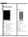
NOTICE
This is a user guide for SPR Smart System.
This guide gives you SPR Smart System’s external spec, name,
PAN/TILT Control, the way of attaching peripheral devices and
configuration.
D
The copyright of this manual belongs to Samsung Electronics Co., Ltd.
D
It is prohibited to copy this manual without permission.
D
Any damage or break owing to carelessness is out of our warranty service.
D
Should you need open the system for extention or repairing, it is recommended
that you ask for an engineer’s assistance by contacting the dealer you bought it
or Samsung Electronics Co., Ltd.
D
This product has certification for domestic and industrial use. Also, it has taken
CE for Europe, FCC for the U.S.
Samsung Eco-mark
The Samsung’s own Eco mark helps consumers to easily understand that Samsung develops ecofriendly products. This mark represents Samsung’s continuous effort to develop eco-friendly products.
RoHS compliant
Our product complies with “The Restriction Of the use of certain Hazardous Substances in electrical
and electronic equipment”, and we do not use the 6 hazardous materials-Cadmium (Cd), Lead(Pb),
Mercury(Hg), Hexavalent Chromium (Cr+6), Poly Brominated Biphenyls(PBBs), Poly Brominated
Diphenyl Ethers(PBDEs)-in our products.
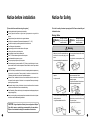
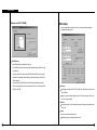
Notice before installation
Notice for Safety
[ Please check these out before using the system.]
This is for the safety of customer’s property and life. Please read carefully and
D
follow the direction.
D
D
D
D
D
D
D
D
D
D
D
D
D
D
D
D
D
Avoid any place that has high moisture, dust or black dirt.
Avoid any place that has direct sun light or heat. High temperature is not good for the
product.
Keep product away from a electric shock or magnetic substance.
Avoid high or low temperature.(Recommended temperature is 5 °C ~33°C)
Be careful not to drop any conducting material into the ventilation hole.
Turn off the system before installation.
Ensure enough space for the cables at the rear of the system.
Avoid any place that may shake the product.
Use the product in areas where it ventilates well.
Radio, TV or Radio devices might be harmful to the system.
Don’t disassemble the system on your own.
Do not put any heavy objects on top of the product.
This device designed to operate under Max. 33°C. When you install this device in the rack,
please consider the Max. ambient temperature. Please install this device Proper ambient
temperature of all park.
CAUTION : When you install this device in the rack, the operating ambient temperature may
be greater than room ambient. Please consider this condition and simulate the Max.
Temperature and install in an environment Compatible temperature.
Reduced Air Flow : Installation of this device in a rack should be such that the amount of air
flow required for safe operation of this device is not compromised. Please provide enough
space to get the proper air flow.
Mechanical Loading - Mounting of this device in the rack should be such that a hazardous
condition is not achieved due to uneven mechanical loading.
Circuit Overloading : Please read the rating in the nameplate and consider appropriate power
supply and supply wiring.
When you are using like a power strips except direct connections to the branch circuit, please
make sure to connect reliable earthing maintained.
Warning / Notice
Warning
Message for problem
that might cause death
or serious casualty.
Only with the same or equivalent type recommended by the manufacturer.
Dispose of user batteries according to the manufacturer’s instructions
Message for problem
that might cause hurt or
damage to property.
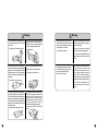
Warning
Make sure to turn off the system before you
install and do not use many plug in one
socket.
• It can cause overheat, fire or electric shock.
Do not bend power cable too much or let
it peeled.
• It might cause fire.
Do not locate in the area where high
humidity or dust exist.
• It might cause electric shock or fire.
CAUTION : Danger of explosion if battery is incorrectly replaced. Replace
Notice
Do not put glass with water, coffee or drink
on the product.
• Any spilt drink can cause problem in the
product.
Please make sure the systems is located in
a clean area and make it dried.
Do not use wet towel or chemical product
to clean the system.
• It might hurt the surface of the product or
cause trouble and electric shock.
Do not plug out the power cable by grabbing
with wet hands or too much force. Do not plug
in if the socket is loose.
• It might cause fire or electric shock.
Warning
Do not disassemble or repair the system by
yourself since the system has high voltage
part inside.
• It might cause fire, electric shock or hurt.
Locate the product in shade where proper
temperature remains and avoid place next
to hot object. Do not place the equipment
or device in the place people visits a lot.
• It might cause fire.
Warning
Replace the battery with the product that
the manufacturer appointed or the equal
product. Dispose the battery according to
the manufacturer’s instructions.
• It might cause an explosion.
If HDD is full, change the set-up to keep up
with recording and check again if you allow
the data to be erased.
(Refer to the “The record is not available”
item in the fault report, the supplement.)
We do not bear the responsibility for the
data corruption caused by the user’s lack
of care.
The bottom surface must be moisture-free.
And, be cautious about any possible delicate
facters, such as ungrounded extension cable,
abraded power cord, lack of safe grounding.
When any problem occurs, please consult to
an expert .
Position it in an open space with flat surface,
and do not stand it on end or diagonally.
• If it falls down, it might cause hurt.
• It might cause fire or electric shock.
When properly connected to the HDD, the
LED status indicator in front of the system
blinks. Be sure that the LED status
indicator blinks continuously.
If the life of the HDD which stores the data
ends, video data to be stored can be
damaged and unrecoverable. When the
screen is broken while playing the data
stored in HDD in the midst of recording,
please request a service centeror the place
you bought it to replace the HDD promptly.
We do not bear the responsibility for the
data corruption caused by the user’s lack
of care.
The cables of the power cable connectors,
video signal input/output signal, Serial Port
and LAN Cable connectors on the back of the
system can be pressed down and damaged,
if it is set up too close to the wall. Maintain the
distance of 15 cm between back of the main
body and the wall.
The fluctuation of operation voltage must be
within 10% of the regulation voltage, and the
electric outlet must be always ground.
Insulation devices, such as, hair dryers,
irons, refrigerators, etc., must not be co-used
in the same outlet with this system is
recommended for stable power supply.
• It might cause fire, electric shock or hurt.
• It might cause overheat, fire or electric
shock.
Notice
Avoid places with strong magnetic or electrical
field, severe impact or places near a radio or
TV.
Keep it away from magnetic sources, electric
wave or severe tremor.
Be sure to remove the foreign substance
inside the product. It might cause damage.
Keep it under proper temperature and
humidity conditions.
Maintain a low level of humidity and the
operation temperature of 0 °C to 33°C.
Do not put any heavy items on the product.
• It might cause damage.
Notice
Place it away from severe impact or
shock. It might cause damage to the
equipment.
Use a grounded power cable only.
Place it away from direct sunlight or
the heat.
In case it makes weird sound or smell,
pull out the power plug instantly and
consult to a service center or the store
you bought the product from.
• It might cause fire or electric shock.
Well ventilated place is recommended.
• Set up the system, leaving the space of
15 cm or over on the back and 5 cm or
over on the sides.
Please place the machine in a flat and
safe place to avoid risk of damage
occurring.
Ventilate the system operating room well
and fix the cover of the body firmly to
prevent the trouble caused by surrounding
factors.
Ask a service center to examine the
system regularly to maintain system
efficiency.
For a stable power supply, it is recommended
to use AVR(Automatic Voltage Regulator).
By winding Core-Ferrite, you can prevent the
connector connected to this equipment from
producing an effect on EMI.
This is only a recommendation-not essential.
We do not bear the responsibility for the
damage caused by the user’s lack of care.
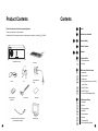
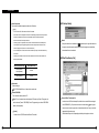
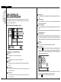
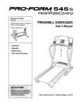
Product Contents
Contents
Notice
[ Check to make sure the box has everything below. ]
Contact your dealer if there is any missed item.
(Optional: Monitor- Recommended monitor is one that supports the resolution of at least 1024 768, 60Hz)
Notice before installation
Notice for Safety
Product Contents
Contents
I. System Outline
SPR SMART SYSTEM
Key Board
1. Product Introduction
2. Feature
II.Multi channel Video Surveillance
1. Mainscreen
2. Screen Division
3. State screen
Mouse
Key
RS-232 Serial Port
Cable
4. Emergency Recording, Alarm off, Setup,
Search, Power
5. PAN/TILT Mode-I
6. PAN/TILT Mode-II
7. Live Audio Data Outputting Feature
SPR Smart Viewer
Program CD
Power Cable
User guide
III. Environment Setup
1. Hardware
2. System
3. Recording/Display
4. Schedule
5. Motion detection
RS-485 Communication conversion cable
(used for PAN/TILT CAMERA)
Monitor(Option)
6. Network
7. Password Setup
8. On-Screen Keyboard Display
IV. Search Screen
1. Run Search Program
2. Search Date and Time Selection
3. Camera Selection
4. Playing Recording
5. Search Tool
6. Audio Setup
7. Data Backup
8. Print Search Screen
9. Motion Search
V. Appendix
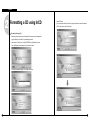
1. Formatting a CD using Direct CD
2. Formatting a CD using InCD
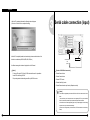
3. Serial cable connection (input)
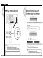
4. PAN/TILT Drive connection
5. External Sensor input and Control
output connection
System Outline
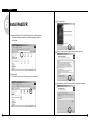
6. Inatalling WebDVR
7. Installing PPP in Windows 2000
8. Setting Guest User, Password and
Account Options.
9. SSC-2000 SYSTEM KEYBOARD
10. DVR Control by SSC-2000 Keyboard
11. External monitor 2 output quality control
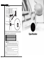
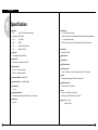
VI. Specification
1. Specification
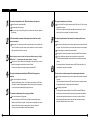
VII. Q&A
1. Q&A
1
System Outline
1
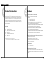
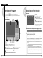
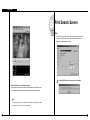
Product Introduction
Digital Video Recorder (SPR-7116/7416) digitally records the video image so it provides clear
image like a picture. It also has a function to record continuously so you don’t have to worry about
2
Feature
High picture quality, speed, and recording
• Maximum of 30 Frame per second (320X240, standard)
Resolution:
the frequent change of tapes. DVR, therefore, is a video recording surveillance system for the
- NTSC : 640X480, 320X240, 160X120
next generation and it is growing very rapidly. In addition to that, it has communication function
- PAL : 768X576, 384X288, 192X144
which enables you to detect remoteness screen even from household and it contains a multi
branch of up-to-date function.
• NTSC method supports various resolution rates - 640X480, 640X240, 320X240 and
160X120 - and is enabled with monitoring and recording features.
(Compressed size of recorded file : 640X480 = Approximately 6KB, 640X240 = Approximately
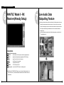
Requirement
4.5KB, 320X240 = Approxmately 2.5KB, 160X120 = Approximately 1KB)
• PAL method supports various resolution rates - 768X576, 768X288, 384X288 and
O/S
: Windows 2000 Professional
192X144 - and is enabled with monitoring and recording features.
CPU
: Intel P-IV 1.5Ghz or more (Depends on situation)
(Compressed size of recorded file : 768X576 = Approximately 7KB, 768X288 = Approximately
RAM
: 256 MB or more
5.4KB, 384X288 = Approxmately 3.3KB, 192X144 = Approximately 1KB)
VGA
: ATI 16MB or more (1024x768, true color)
LAN
: 10Mbps or more
Multi-Channel display and output for multiple sensor/alarm function
• Multi-picture display with 16 cameras
Minimum requirement of SPR-7416 model is as follows:
CPU : Inter P-IV 2.4 Ghz, Memory : DDR 256MB, VGA : ATI 64MB, LAN : 10/100Mbps
• Multiple recording can be done by each 16 sensors
• Possible to produce several output when an alarm operates
• Outputs 16 contact point alarms.
Several Detection
• 1, 4, 6, 9, and 16 split screen
Recording schedule and Quick search
• User can assign recording schedule by week day, Saturday, Sunday, and holiday.
• Recording table is configured by date, camera, and time to have a grasp of recording
status.
1-1
1-2
System Outline
Process multiple image
Control from remote area with Camera
• Processes image through motion detection
• When using PTZ camera, it remotely controls camera’s Pan/Tilt/Zoom.
• You may select up to 5 areas per image and control its sensibility.
• Improve image quality (Clear and flexible)
• Zoom in/out
• Adjust brightness
What is PTZ camera?
PTZ is abbreviated from Pan/Tilt/Zoom. PTZ camera is different from
other normal camera in that it can rotate, adjust, zoom in & out itself.
Warning sound occurs when there is any movement
• When any movement is captured within selected area, beep sound will occur immediately.
Water-Mark
• When video footage requires a higher level of authentication, digital watermarks can be
Auto Control
embedded into digital video images to verify whether the recordings are genuine or have
• This function is to automatically control 16 channel with setup time.
been illegally modified. Authentication can be verified easily using watermarks and would
• This function automatically controls (On/Off) light and siren.
be valid as court evidence if required.
Watchdog
• When system is not working normally, this will automatically reboot the system and restore
everything back to normal and safe.
Emergency Screen Transmission
• If any movement is captured, then it will automatically connect to the Remote and sent
the captured image.
Search from remote area
• This function enables to search images from remote areas through LAN
Output from External monitor
• All of 16 DVRs can connect to one specific Remote at once and it detects, searches, and
• Image can automatically be converted to real time image not only from PC monitor but
controls each DVR.
Search Multiple Screen
• Display images into 1, 4, 9, 16 split screen or into Panorama
Search Multi-Camera
from normal monitor as well.
Security of System
• Intentional modification can be made from outsider during operation so the system will
auto check the original password to increase security.
• Images that were recorded by multiple cameras can be seen at once
Data Backup
Audio Recording
• Stores back up data using Hard disk, CD-RW, DVD, Network
• It simultaneously records and searches a channel with audio.
Detect Remote Area
How to control external monitor output quality
• Detects from Remote area using LAN
• This to gain optimal performance from a long distance installation for the external monitor
output via control switch.
1-2
1-2
Multi channel Video Surveillance
2
Multi channel Video Surveillance
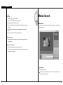
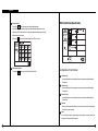
1
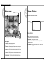
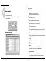
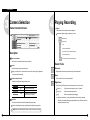
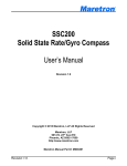
Mainscreen
State Screen
System Status
Division
Function Select
2
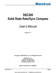
Screen Division
Screen division can be done by [Screen Division] button
PTZ camera display
PAN/TILT
REC
Recording status
Camera name
Screen Division
Camera : Display the position of the camera under surveillance.
Alarm/Sensor/Audio toggle button
Camera/Sensor/Alarm/Audio
The default value is 1[POSITION1]. But you can modify it in setup.
Screen Division button
Function Select
Recording Status : Display recording status of each camera.
Description
For continuous recording in red ”Rec”, and for motion detection recording in blue ”M Rec”
and nothing for no recording.
Screen Division : Displays the selected camera image
System Status : Display time/date, HDD usage.
Screen Division : Select the live image under surveillance. Maximum 16 live image can be
PTZ camera display : When the installed camera is PAN/TILT, displays green
“PAN/TILT”
displayed (1, 4, 6, 9, 16 division, 4division rotation mode is possible.)
State Screen : Display for the status of continuous recording, sensor, alarm, motion, audio
or network
Function Select : Emergency recording, alarm off, configuration and displaying recorded image
Camera/Sensor/Alarm : Display status of camera recording, sensor/alarm and audio.
Alarm/Sensor/Audio : Toggle for display and control of alarm/sensor/audio in rotation.
2-1
2-2
. Multi channel Video Surveillance
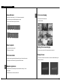
Screen Division
Full screen display
• Screen division can be made in 4, 6, 9, 16, full screen and quad rotation.
(Screen division type can be different depending on model.)
• Any click on certain camera will give you full screen.
• Full screen mode of divided screen.
• It will look as below.
SPR-7416
4ch
6ch
9ch
16ch full screen rotation
9ch
16ch Full ScreenRotation
SPR-7116
4ch
How to operate
Click the division button you want.
Divided screen will appear.
Full screen mode
• Left click on certain image under divided screen will give you full screen of the camera.
• Clicking again on the full screen will give you previous divided screen.
Exiting Full screen display
• To go to previous mode from ”full screen display” press right click.
Empty Screen
• If no camera is connected to the channel or the channel is disabled below logo will
appear on the screen.
Rotation by division
• Click Rotation button after selecting the screen division button among 4, 6, 9 or full
screen button.
• Click Rotation button to exit screen rotation mode.
Blue : No camera is connected
2-2
Grey : The channel is disabled.
2-2
. Multi channel Video Surveillance
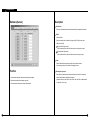
3
4
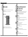
State screen
Emergency Recording, Alarm off,
Setup, Search, Power
• Display the status of event such as continuous recording, sensor, alarm, motion, audio or
Emergency Recording
network connection.
• State screen displays [ time of event - camera number - event type ]
You can start recording regardless of recording schedule while monitoring live image.
All the installed cameras start recording together and “REC” appears on screen.
You can stop emergency recording by clicking once more.
State screen
Recording term is normal term on each camera’s setup.
Alarm off
Time of event
Camera number
Stops alarm signal
Event type
Alarm output can be used together with sensor or motion detection and the output
duration is adjustable.
When the button is pressed on : Alarm output is impossible or alarm output is on halt
When the button is not pressed : Alarm output is possible
Setup
Click on this button will bring up setup window.
Setup windows consist of six windows.
Above Event
Below event
Press ”OK” button to save adjusted configuration. Press ”Cancel” button to cancel the
adjusted configuration.
Password can be used to make it secure.
Camera number : Displays the current camera number in order.
Event movement : Use this button to move up and down to see other event
Search
Click on this search button execute search mode
This is used to search recorded data and recording and monitoring is possible during
search.
Power
Use this to power off the system.
Password can be used to make this function secure.
2-3
2-4
. Multi channel Video Surveillance
5
PAN/TILT Mode I - Speed Dome
How to PreSet
Feature
How to Preset
Display current date and time
: Location of camera can be appointed from 1 to 10
PAN/TILT
: controls camera in left and right / up and down / diagonally adjust it
Change the camera direction to anywhere you want
FOCUS
: adjust focus of the camera lens. (not applied to AUTO FOCUS lens)
Select Preset number
IRIS
: adjust IRIS Out of the camera
Select “D“
ZOOM
: adjust Zoom In/ Zoom Out of the camera
(It will convert from “Setting“ to “No Set“ and location of Preset will be specified).
P/T Speed
: adjust Speed Dome camera’s movement speed
PreSet setup
: PreSet setup for Auto PAN/TILT function
Auto Preset
: Camera tours automatically along the configured path. Up, down or
left, right button cane stop auto function.
How to delete Preset
: Delete the specified Preset location
Select any Preset number you wish to delete
Auto Pan
: excute Auto Pan
Select trash can picture icon
PATTERN
: excutes Pattern1 which was memorized from camera’s pattern for 30
(It will convert from “No Set“ to “Setting“ and you can relocate preset location.)
sec.
OSD Menu of camera
: OSD menu will appear.
PAN/TILT number : You can move camera toward the position recorded.
Display mode
2-5
: convert from PAN/TILT mode to Live display mode
2-5
. Multi channel Video Surveillance
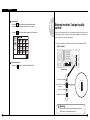
6
PAN/TILT Mode II - RX
Receiver(Already Setup)
7
Live Audio Data
Outputting Feature
By zooming in one camera channel with the audio feature in the Monitoring modem, the user can
output both the video data and the audio data in real time. (If the user zooms in one channel,
“Volume” window will appear only for the channel where the audio data is outputted in real time.
“Audio” display in the Monitoring mode indicateds that both the video data and audio data
are being stored.)
For more information about setting Live Audio Data Outputting feature, see “Audio Setup” in
Recording/Display” part.
Description
Indicates current date and time
PAN/TILT
: controls camera in left and right / up and down / diagonally adjust it
FOCUS
: adjust focus of the camera lens. (not applied to AUTO FOCUS lens)
ZOOM
: adjust Zoom In/ Zoom Out of the camera
LIGHT
: On/Off function for Camera light
WIPER
: It operates camera’s wiper
POWER
: To On/Off camera’s Power
Display mode : convert from PAN/TILT mode to Live display mode
AutoPAN, LIGHT,WIPER,POWER button may be indicated differently based on the
type of RX Receiver. (It is because different manufacturer have different functions to
support each).
2-6
2-7
Environment Setup
3
Environment Setup
Description
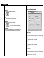
1
Hardware
Select Camera : To decided which camera to use
When Camera Button is pressed: Camera in use
When Camera Button is not pressed: Camera not in use
Press set up button for system setup
Screen which inputs password will be appeared. The screen will not be appeared
if password is not created.
camera not in use’ is selected, it may lower the recording speed, so it is important to select
camera which you will use only.
Name
: Input the name of place which the camera will be installed
Sensor
: Input the sensor number which will be used with each camera
1 up to 16 external sensors can be connected and if the external sensor activates then
linked camera will record the image.
Input additional comma(,) in case several external sensors are to be linked together.
For example) When operating external sensors number 2 and 3 and you wish to record
the image of number 1 camera, then input ”2, 3” on Camera ”Sensor” Category.
Hardware [Camera]
P/T
: Check if the selected camera is PTZ.
In this case, PTZ related equipment should be connected and selected camera will indicate
PAN/TILT on top of image.
P/T Type
: Model of RX-Receiver and Speed Dome Camera which are compatible with system and
RX-Receiver’s Control protocol are inputted. Select the model compatible with current model.
P/T ID
: Select ID from P/T connected to the system.
Baud Rate
: Baud rate might be different depending on the type of PAN/TILT camera.
Currently 4800BPS, 9600BPS, 19200BPS and 38400BPS are supported.
Sensor Preset interworking
: When data is inputted into a sensor interworking with the corresponding camera, Sensor Preset
Interworking feature will move the image preset in Pan/Tilt mode.
For more information about presetting the position for Pan/Tilt mode, see “Presetting” in
“Pan/Tlit Mode” part.
3-1
3-1
Environment Setup
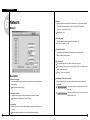
Hardware [Sensor]
Description
Select Sensor
: The number of external sensors and input terminal should be correspondent to each other.
NC/NO
: Configure Sensor
Each time when the button is clicked it will change to [NC]<->[NO] and vice versa.
(Default is set to [NC])
NC (Normal Close Type sensor)
: While on detection mode, choose this when sensor is near the point of contact
NO (Normal Open Type sensor)
: While on detection mode, choose this when sensor’s contract point is open.
Alarm
: While on Sensor detection mode, alarm will be on when sensor activates.
If the recording mode is set to “Continuous” beeping will not work.
Function
Recording time by sensor
: When there is a signal from sensor connected to system, this function is to setup time
3-1
• Record camera image when the external sensor signal is triggered.
which will record camera’s image linked with sensor.
• Beep when the external sensor detects any signal.
(Possible to setup 1sec, 5sec, 10sec, 20sec, 30sec, 1Min, 2Min, 3Min, or Manual mode.
• Activate external control output on receipt of sensor signal.
Factory value is set to 1 sec)
3-1
Environment Setup
Hardware [Alarm]
Description
Select Alarm
: This button is to choose output of alarm terminal you wish to setup.
When button is pressed: Appropriate alarm is selected
When button is not pressed: Appropriate alarm is not selected
Name
: Input name of alarm to use
Input Sensor No.
: If you want alarm to automatically operate from external sensor, input external sensor that’s
linked to alarm.
For example) If you wish to operate number 1 sensor when number 3 activates, choose
alarm 1 and input ”3” for following item.
Input Camera No.
: In order to activate external alarm by motion detection input the camera number that will
detect the movement.
Function
• It indicates whether alarm will be used or not and setup sensor and time of output produced.
• Output of alarm will be either ON/OFF when any sensor or moving(motion) object is captured.
Ex1.) If you want to activate alarm 1 on detecting movement on camera2 , select Alarm1
and input camera number “2”
It can control light, siren, speaker, and other external equipment.
Auto ON/OFF time(S)
: Input continuance of operating time for control output in second after sensor signaled.
(Possible to setup 1sec, 5sec, 10sec, 20sec, 30sec, 1min, 2min, 3min or manual mode.
Factory value is Manual mode.)
3-1
3-1
Environment Setup
Description
Hardware [External monitor]
Select Camera
: Choose the camera which will produce output by external monitor.
The output will be automatically produced according to setup time.
When button is pressed: Appropriate camera is selected
When button is not pressed: Appropriate camera is not selected
Select time(S)
: The output from external monitor should be assigned in second (From 1 sec to 10 sec)
Each camera’s image will be displayed by rotation for the designated time (sec).
Input Sensor No.
: The image will be displayed onto external monitor when the linked sensor detect signal.
Input Camera No.
: The image will be displayed onto external monitor when the camera detects movement.
Out time by event
: Setup the duration to display onto external monitor when linked sensor or linked motion
detect signal or movement.
(1 sec ~ 10 sec is available, factory value is 2 seconds.)
Description
• The external monitor function is to transmit the image displayed on DVR monitor by using
a general analogue monitor(TV, general monitor).
• You can print the images as sequentially converting the images from the camera from 1 to
16 according to the designed time(sec.) or as the split screen system.
• The images from a given camera can be transmitted to an external monitor as detecting
the monitors of images of a camera.
• The images from a given camera can be transmitted to an external monitor as detecting
the motion of images of a camera.
External Monitor
: Select the image display mothed to be transmitted to an external monitor.
Quad mode : Display the image to be transmitted monitor as the split images.
Automatic Selection : Display the selected camera sequentially on an external monitor
during the time setting.
[Note]
• When you install the system and the quality is bad on the external monitor please refer to chapter
11 (how to control external monitor output quality) in the manual.
• Press the right button of a mouse on the image screen of the camera to be transmitted to
an external Monitor on the monitoring screen, and you can transmit the relevant image to
an external monitor.
[Note]
• For the SPR-7116 Model, the external monitor connector on IO board is not operational, The
external monitor connector on display board must be used.
[Notice]
External moniter setup function only can be applied to external monitor output 1, not external monitor output 2.
When try to install external monitor through external monitor output connectors on the board, please refer to
5-11. External monitor 2 output quality control
3-1
[Note]
• The same image is displayed on external monitor 2 as on Main monitor(VGA)
3-1
Environment Setup
2
System
Model
: Contains information of program
System [System information]
Distributor
: Input name of installer
Other
: Input additional information for the system.
Note
: Input information related to system repairing.
Language
: Input information related to system repairing.
Example) Select one of the languages that you want to use such as Korean, English,
French, Chinese, Italian, Spanish and German, and press [Save].
In the multi-language supports function, select a language, and convert to a monitoring
screen.
Description
VIEW code
: Default is set to 100-001
The value may change at your discretion but anything must be inputted.
When connecting from SPR Smart Viewer(Remote) to SPR Smart View(DVR), it
Then, the language that you select is applied to the sysem.
DVR ADDRESS
: DVR address shall be entered to control DVR by keyboard by interlocking DVR and
SCC-2000 key board.
simultaneously searches and compares site code and Password. If either site code or
password is wrong, then the connection will not be made.
It is available to enter 0 ~ 255 for DVR address.
In case of controlling the DVR by using SSC-2000 keyboard, SSC-2000 keyboard
Location
should be connected by each number set in DVR address. For further information of
: Input name of place where system is installed
SSC-2000 keyboard, please refer to the product manual of SSC-2000 keyboard.
Version
: Displays the version of installed SPR Series DVR program.
3-2
3-2
Environment Setup
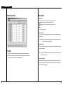
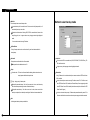
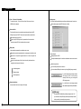
System [Backup setup]
Description
Backup schedule setup
• This backup media will show reserved list of backup data which will record data, assigned time
for backup, and etc.
• According to assigned backup schedule, it will backup in order.
Calendar
• Calendar will appear in Pull-down type like picture above when you click on [>] button indicated
Method to add backup schedule
Title
: Input name to be add on backup schedule list
Date/Time
: Selects start and end time for backup data
It must be setup after current recording time.
If it was setup before current recording time, then it will be ignored and won’t be added
to the list when [Add] button is clicked.
beside the current date.
Rotate option
You can check backup schedule list assigned by days and current date will be displayed if you
: Repetitive rotation cycle can be maintained by assigning assigned date and
click ”Today”.
Add
: It adds assigned and rotation time of backup schedule data and data to be recorded in backup
media.
Delete
: It deletes reserved category from backup schedule setup.
Setup
Year/Month/Week/None basis for backup data
If [None] is selected, only one day setup can be made for assigned date/time.
Backup start time interval after
: After backup data has finish its recording, it assigns when the backup will start after data
has finished its backup.
Possible select time will be from 1 to 4 hours
: If [Setup] is not selected, reserved information will not be stored from backup schedule list.
3-2
3-2
Environment Setup
Method to select backup media
Media list
: Choose backup data to record backup media
It can be added up to 8 from media list and if fail to record on initially setup media, it will
automatically back up to next media.
Selection should be made as following: HDD, CD-RW, removable drive, Network drive
except floppy disk, etc. It supports almost every language oriented logical/physical
media.
You can select remote drive using IP address.
Up/Down/Delete
: Priority of backup media can be move from down/Up, and it can delete media that’s
already setup.
Local drive
Add media
: Backup data can add media which will be recorded
Backup media can be added maximum of 8
You can select HDD or removable drive (MOD, DVD-RAM, ZIP, USB HDD etc), CDRW, and Network drive.
It supports every drive language oriented logical/physical media.
Setup
Overwrite mode : This function will record data after deleting old data when there is not
enough space available to backup the data
Remote drive
: Using IP address, this is used when backup from remove area where SPR Smart Viewer
S/W is installed
Priority : Assign priority of backup data
In order to backup from remote area using IP address, remote PC or File Server must
Backup after precedent backup : Wait until the current work is done; start the backup
have SPR Smart Viewer S/W installed, and Remote Backup Server program (provided
after current backup and waiting data have finished their backup.
when SPR Smart Viewer S/W is installed) should be executed (refer to Manual for SPR
Backup after current backup : Start after current work is done; when current data’s
Smart Viewer Program)
backup is completed, do not backup the waiting data if the other data was selected first.
In order to do remote backup setup, IP address and password located by remote PC or
file server should be the same and remote backup server program should be executed
Add
: Add designated backup to backup schedule list
3-2
3-2
Environment Setup
Remote drive
Connection Fail
: If selected IP address and password is different or Remote Backup Server program has
not been executed from remote PC or File Server, then connection will fail and you may
not be able to choose backup media drive.
Indication of Backup status
Select drive
: Input IP address and password and select [Select Drive].
In order to connect to Remote backup server for remote backup, remote IP address and
registered password from Remote Backup server program is needed.
(If password is not registered,select [Select drive] button after IP address from remote
site is inputted.)
Drive path
: If connection is made successfully using selected IP address and password, you may
choose an appropriate backup media drive from remote PC or File server.
Backup
: While backup is progressing, animated icon
will appear on top of screen. When
you double click on it, you can check on current data’s backup progressing process and
waiting backup data list.
Click [Hide]Button to close backup window
3-2
3-2
Environment Setup
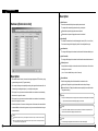
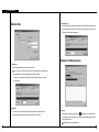
System [S/W Update]
Check integral package file & program installation
Installing process of a program window will appear when you designate package folder
Description
When [S/W Update] is selected, Intelli Upgrade window will be executed to let you choose
Installing process will show twice for testing integration package file and for program
installation. SPR Smart View program, which was executed during program installation,
will end
new package for program version. This function is to upgrade to a new version that’s stored
in hard disk or joint network folder.
Description
Select Package directory
Click [OK] after selecting hard disk or joint network folder which is store in a new version
Appropriate folder must include package folder(Data1, Data2, Data3, Data-a, Data-b,
etc.) or all files from package folder must be included in one folder.
When upgrading to a new version using Intelli Upgrade, upgrading does not support
floppy diskette. Therefore, we recommend you to upgrade after copying the whole media
or on a hard diskette.
System reboot
: System need to be restarted when upgrading a new program version is completed.
If there is no file or package folder in certain folder due to a wrong folder designation, or if
the damage had occur to the file, then it will not be considered as a normal package so
the program will not upgrade normally.
3-2
3-2
Environment Setup
System [Other]
[Note] What is WaterMark ?
BMP and JPEG images can be modified anytime by user.
To ensure the original image which can be modified, special protection called
’watermarking’ is enabled onto the image.
Any changes to an original image, including just one pixel, will inform you that the image
has been modified.
When recorded image was modified from SPR Smart View program, WaterMark
authentication and WaterMark check will tell you whether the image was modified or not.
H.D.D REC method
: Setup for HDD replace, when the space of the HDD the recorded video is stored, is
not available.
Monowriting(The button pressed state) : One-time recording only.
(HDD is to be changed after it had reached its max. capacity.)
Overwriting(The button not-pressed state) : This will overwrite without having to
change HDD.
A message box will appear with a ‘Beep’ sound when it is time to change
Description
HDD.
Enable/Disable HDD Warning
: This function is to detect the possibility of HDD drive error in advance and info it to the user.
A buzzer sounds in the system when the bad sector and overheating generate in HDD
disc.
When the buzzer sounds in the system, please replace HDD disc with normal on
immediately.
System Restart time
Video Format
: Appear Video Format, NTSC or PAL
: setup the automatic rebooting time for everyday. (This is used to make system more stable.)
Default setup is ”Used”, in order to disable this click ”Used” button again.
It will change to ”No Use”
Watermark setup
Using watermark
This function inserts Watermark authentication mark on image to be recorded.
When this function is selected, image will indicate WaterMark on the image.
Displaying watermark text
3-2
Date display type
: Choose date display type.
Below format is available.
Display ) YYYY-MM-DD, (ex: 2000-12-31)
This function inserts Watermark authentication mark on image to be searched
MM-DD-YYYY, (ex: 12-31-2000)
When this function is selected, image will indicate WaterMark on the image.
DD-MM-YYYY, (ex: 31-12-2000)
3-2
Environment Setup
Clock - 12 Hours or 24 Hours Mode
: To convert clock mode - 12 Hours or 24 Hours. When 24 Hours mode is in use,
AM/PM will not be displayed.
Storage setup
: This function modifies possible disk space of data and allocation status for each drive
Window below appears when [HDD Information] is clicked
Control card Port
: This set output Out port and communication transmission speed (bps) to use SSC2000 system keyboard, PAN/TILT camera, sensor input and alarm output functions.
The available control port is COM1.
in case of using SSC-2000 keyboard, it is requested to set the communication
transmission speed of DVR and keyboard as the same speed.
Display setup
: It sets up status bar appeared from surveillance screen or area
When button is pressed: Appropriate status bar or area appears from detection mode
Drive allocation
When button is not pressed: Appropriate status bar or area don’t appear from
Displays Allocation of HDD
detection mode
Currently available disk space for each drive and allocation status can be checked
In order to find out the status of Audio, Sensor, Alarm click (audio/sensor/ alarm
toggle button) from lower part of the screen.
Modify storage structure
You can modify the allocation on each drive
Audio recording status
You can re-allocate DB setup for each drive by clicking [Modify storage structure].
Sensor input status
If you click [Modify storage structure], the button
will change to [Cancel to modify storage
structure]. With this way you can change the
HDD storage structure.
Control output status
Set quad rotation time
If you click [Cancel to modify storage structure]
button, [Modify storage structure] will be disabled.
: setup the rotation time in sec to display in 4ch display
[Warning]
Recorded data will be deleted by modifying storage structure. So if
you would like to modify DB storage structure please backup the data
before you modify the recording storage structure.
3-2
3-2
Environment Setup
Storage Structure re-allocation
Click [Modify storage structure] and exit the system in the surveillance. Then the system
will reboot and you can re-allocate the storage structure.
Once you reboot the system below window will appear and select the drive to allocate
3
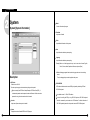
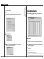
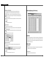
Recording/Display
Recording/Display [Recording and Transfer]
again. Finally click [proceed] button.
Format selected disk drive
Format newly allocated HDD
Description
Select Camera
: Select a camera no. to set the display size, compression quality and transmission quality by
Selecting File System
camera.
Select the type of File System that will be formatted and click [OK]. Then new storage
The camera setting is displayed on hardware tab [Camera] and indicated camera are the
structure will be created and SPR Smart View starts up.
channels that are currently recored.
The display size, compression quailty and transmission quality are independently set and
saved by camera no.
Recording frame rate per camera
: Adjust the number of frames to be saved by camera.
Put amount on a scroll bar and adjust the amount of recording as pressing the left button of
the mouse. (The amount of recording by camera is indicated by number on the right side.)
3-2
3-3
Environment Setup
Screen size
Audio
: Choose screen size
: Decided to record audio for appropriate camera
Basically, resolution for 320 240 is best suitable for file size
(display and recording speed will improve twice when resolution is set to 160*120
When REC button is pressed: It records voice for appropriate camera.
When REC button is not pressed: It does not record the voice for appropriate camera.
but it will decrease image quality. 640 480 resolution will give you excellent image
quality but recording speed will be decreased).
You can setup voice for specific camera and it records with voice signal that is being
Default value is 320 240 (based on NTSC).
inputted to microphone terminal.
Supported resolution is as below :
Voice is recorded according to recorded time for image and the sound data will be recorded
NTSC : 160 120, 320 240, 640x240, 640 480
when the video signal start its recording. Therefore, sound data will not be recorded if the
PAL : 192 144, 384 288, 768x288, 768 576
video data was not recorded.
In order to record voice, system must be installed with sound card or exclusive audio board.
Quality(Recording Quality)
(If Sound card or audio board is not installed, you can’t setup audio category and it will be
:To setup image quality
ignored).
Higher value gives higher image quality but file size for per frame will increase.
Only 1 channel can record voice when using sound card installed on main board. Voice
Default value is set to ”Normal”
recording is supported up to 8 channel when using Samsung Electronics Co., Ltd. made
Image size and compressed image is closely connected for the file size to be recorded.
exclusive audio board.
If sound card and exclusive audio board are installed simultaneously, then we recommend
Transfer Quality
you to record voice using audio board.
: Setup the quality of image to transfer when connection with SPR Smart Viewer
If both SDC-1000A and SDA-1000 are installed, SDA-1000 will be used for saving the audio
Higher value gives higher image quality but file size per frame will increase.
data.
Default value is set to “Normal”
Image size and transfer quality is closely connected for the file size to be transferred.
[Notice]
• When trying to backup already recorded data, it can backup with voice and it is possible to
record in specific drive. (But, if the voice data was recorded using audio board then backup
cannot be made and it will be supported from later version.
• If sound card is embedded, 2way audio communication is possible to communicate with
remote S/W.
• If 2way audio is connected using sound card, audio recording will discontinue.
• Window must be setup separately for sound card when using 2way audio with sound card.
• By clicking on
button after zooming in one channel in the Monitoring mode, the user
can output both he video data and the audio data if the camera supports both.
• Outputting living audio through the dedicated sound board in the Monitoring mode does not
affect the setting to save the audio data.
3-3
3-3
Environment Setup
(Interworked) Audio Output
Recording/Display [Emergency Frame]
: Through detection of motion, an external sensor’s detection, or user’s right-clicking the
mouse, the audio data along with the video data of an external monitor can be outputted.
By interworking with the connected external sensor, the audio data of the corresponding
channel can be outputted based on generation of sensor signals.
The audio data of the corresponding camera can be outputted according to detection of
the moving camera images.
By right-clicking on the video channel of a particular camera in the Monitoring mode, the
user can output the audio data of the corresponding channel.
Description
Select Camera
: Type in the camera number to set the frames to record per camera during an emerency.
The list of cameras set in Hardware [Camera] tab will be displayed, and displayed
camera number represent channels currently being recoreded.
The recording frame rate per camera will be separately set and saved for each camera.
Recording frame rate per camera
: The user can adjust the number of frames to be recorded during an emergency for each camera.
Left-click on the scroll button, and set the recording frame rate per camera (that will be
displayed as a number on the right side.)
It is recommanded to increase the recording frame rate per camera when a signal is
inputted to a sensor connecting to a certain camera.
[Notice]
• If an emergency situation occurs by Emergency Frame feature, the recorded frames of other
cameras may be lower than he setting.
3-3
3-3
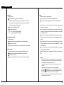
Environment Setup
Recording/Display [Display]
Input Sensor No.
: Select whether to use the sensor inerworking the camera.
: The sensor interworks with the corresponding camera.
: The sensor does not interwork with the corresponding camera.
If a signal is generated is inputted in the sensor interworking with the camera, camera
images will be recorded according to the frame rates setting.
Input Motion No.
: Select whether to use the motion inerworking the camera.
: The motion interworks with the corresponding camera.
: The motion does not interwork with the corresponding camera.
Select time(S)
: Set the Time to record camera images when signals are inputted in the sensor or motion
Interworking with each camera during an emergency. (The conversion time is from 3
seconds to 3 minutes.)
Description
Video loss Alarm
: Alarm and beep are generated through he control number that is inerlocked when Video
Video Loss is generated.
1) Alarm
When Alarm button is pressed : Alarm is activated.
When Alarm button is released : Alarm is not activated.
2) Beep
When Beep button is pressed : Beep is activated.
When Beep button is released : Beep is not activated.
3) Alarm Duration
You can set he duration when alarm and beep tone are generated by this function.
You can select a control number that is interlocked by Control Interlocking when Video
Loss is generated.
Duration can be set by hour , minute or seconds.
3-3
3-3
Environment Setup
Recording/Display [Full Screen]
Big Display in 6 Division Mode
: Zooms in the camera image selected from 6-division mode to the full-screen size.
Use Big Display : To zoom in the selected camera image to the full-screen size.
Not Use Big Display : Not to zoom in the selected camera image to the full-screen size.
The user can zoom in the camera image in 6 Division mode, and the enlarged image will
be kept upon conversion.
All camera images except the camera image selected in the 6 Division mode will be
converted.
[Notice]
• SPR-7416 support 6-division mode.
Recording Period
: Select the period to store the video data.
Then, the data will be kept during the period set here and will be automatically detected
after the period expires.
This menu is applied from the present day, and the user can select the recording period
by day.
In the factory, “Not Use” is set as the period.
Fuctions
The camera image remains as a full-screen image according to the setting previously
made when signals are inputted in the camera or motion interworking with each camera,
and upon the user’s choice, buzzer sound may be generated when the camera image is
converted to full-screen image.
VIP (Video Interface Port)
: The VIP function of VGA card is to reproduce the monitoring screen image with high
resolution image.
Description
Select Camera
: This reproduces the monitoring image with general.
: This reproduces the monitoring image with high
: Select the camera number to make settings - interworking Sensor, Interworking Motion,
Full Screen, Conversion Time, and Buzzer Sound.
resolution image.
[Notice]
• At the time of factory release, it is set as ‘VIP Used’.
3-3
Input Sensor No.
: Select the camera to interwork with the camera.
3-3
Environment Setup
Input Motion No.
: Select whether to use interworking Motion feature.
Full Screen
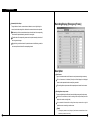
4
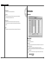
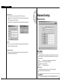
Schedule
Schedule
: Zooms in the camera image to the full-screen size when a sensor is inputted into a
sensor interworking with the camera or motion.
Select Time (S)
: Set the time to convert the full-screen image to the previous image in seconds.
For the conversion time (in seconds), each camera image remains as the full-screen
images.
beep
: Select wheher to use buzzer sound after zooming in the image to the full-screen size.
Description
Select Camera
: Choose camera number to use
Copy to All
: Information of currently selected camera will be copied and applied to every camera at once
Setup Recording time
: This function is to set recording type for selected camera by each day and time.
Select time of day and drag it to select area and then select recording mode form [Record
Mode] (C/M/S/P)
If you need to set in minutes, double click on appropriate time then it will be set in minute.
01 ~ 59
minutes
3-3
3-4
Environment Setup
Record mode (C/M/S/P)
Simple mode
: This function is to set recording type with day and time for selected camera.
: This function lets you to select by minutes instead of hours depend on recording mode.
After choosing day and time from selected camera, selecting more than 1 record mode will
When [Simple mode] is selected it will convert to [Advanced mode]and gives more option to
change selected time within selected time.
setup time. You can set different time for each time.
If you erase all the record type from [Record Mode], selected setup time will change to no
Set holiday
record mode.
: You can pick any specific day of the year and set it as holiday
Default is ’Motion & sensor record’ of 24 hour continuous record.
Indication by record type
• C : Continuous record
• M : Motion record
• S : sensor record
• P : free-alarm record
[Warning]
Supported record type
• no record
• continuous record
• motion record
• sensor record
• motion and sensor record
• motion & free alarm record
• sensor & free alarm record
• motion &sensor & free alarm record
You must select [Save] button from [Schedule setup] in
order to store information on any changed holiday.
Setup Holiday
[Tip]
Continuous Record
- This is used when continuous recording is done without using motion detection.
Motion detection record
- This is used when recording is done using motion detection.
Sensor Record
- This function is to record by inputted sensor signal.
- Sensor setup can be done by camera and use time. If sensor is captured within selected time,
related camera image will be recorded or related control will operate.
- Sensor input signal will be ignored if anything occurs outside the setup time.
- If related camera or time line is set to ’Continuous Record’, then Sensor Record cannot be used.
Pre Alarm
- When a motion is captured on camera, then camera will record every moment of motion
occurrence in addition to five seconds before the motion was detected.
(But, recording speed may decrease if you setup several cameras with it).
- If the appropriate camera or time is set to ’Continuous Record’ you cannot use Pre Alarm function.
3-4
Calendar
: Select any day to designate as holiday
<<
: Move to prior month
>>
: Move to next month
Today : Shows current Month/Day/Year
3-4
Environment Setup
Rotate
: You may choose specific Month/Day/Year as holiday
If you select [None], one day will be assigned and for that specific day only.
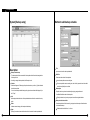
5
Motion detection
Motion detection screen
Holiday list
: This function is to show designated holiday and its repeated date or period in a list
Any additional holidays will be stored in the list in an alphabetical order.
Add
: This function is to add holiday you have designated.
Designated holiday will be added to [Holiday list] when you click [add].
Detection area
Delete
: This function is to delete stored holiday.
In order to do this, select the date you wish to delete from [Holiday list] and click [delete].
Functions
System starts recording when it detects any activity in the detection area without using
sensors.
Description
Select Camera
: Select the camera to setup
Sensitivity
: Adjust the motion detection sensitivity
Default value is “80”, which is the most proper
3-4
3-5
Environment Setup
Alarm(M)
: System makes beeping sound to alert when there is any activity in the selected time.
Color/Monochrome
It sets the color or monochrome display of a conneced camera.
When Alarm(M) button is pressed on : Alarm beeping works.
[Color/Monochrome] is operated by a toggle mode and when a connected camera is a
When Alarm(M) button is not pressed on : Alarm beeping does not work.
monochrome one, it is necessary to set the display as the monochrome mode.
System beeps only when activity is detected in the selected time zone in recording
If the monochrome camera is connected under the setting of [color], the color of a specific
schedule.
camera may be in appropriately displayed.
System does not beep if the camera is set to ‘continuous recording’
Enable/Disable Convert Camera
Brightness / Hue / Contrast
: This function is to hide the image of each camera from the monitoring screen.
: This hide the image of the selected camera from the monitoring.
: Adjust Brightness, hue,and contrast
: This does not hide the image of the selected camera from the
Default for camera is all “0” , and the range is -127~126 and adjustable to each camera.
monitoring screen.
(Proper setup is required depending on situation)
Enable / Disale Auto Gain
The brightness control for external monitor output is automatically controlled by the DVR
system (The Auto gain function can only be selectable on the SPR-7116 model.)
[Notice]
• The camera having the function of security camera hides the image of camera from the
monitoring screen but does not affect the recording.
• The camera having the function of security camera does not show the image even in the Viewer.
Motion Detection Area
Select the camera number and draw detection area using left click dragging.
Maximum five detection area can be made.
To remove the selected motion detection area drag mouse pointer toward out of box.
Default
Restore the default color configuration for the camera by clicking [Default] button
Area draw
Entire area will be under motion detection mode when you click on [Area draw] button.
All area draw
Entire area for every camera will be under motion detection mode when you click on [All
area draw] button.
3-5
3-5
Environment Setup
6
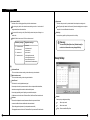
Network
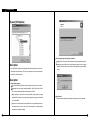
Network
Password
: Input required password to connect from SPR Smart Viewer p.c. (4 digit number is possible.)
[Password] : Input password required to access to DVR from SPR Smart Viewer.
[Confirm]
: Input once again to confirm.
Default value is “1234“
Viewer limite setup
: This function is set the number of Viewer allowed to connect to View.
(Max. number of connection : 1 ~ 128)
Live Stream Bandwidth
: It is availabled to set the bandwidth when transmitting the picture data by network.
(768Kbps, 1.5Mbps, 2.0Mbps, Unlimited)
Type of connection
For remote connection LAN, PSTN, ISDN, Leased Circuit can be used.
ISDN or Leased Circuit using router can be used. ISDN or PSTN can be used to connect
to DNE without router directly.
Check on “No Use“ for no connection
Description
Sensor for emergency
: If the sensor detects any signal it sends alarm to Remote with the recorded image during the
designated time.
Click the sensor number to configure
Allow/Disallow Transfer Convert Camera
: This function allows to see the image of the camera having the ‘security channel’ function
from the Viewer.
: This shows the image of the security channel camera from
the Viewer.
Emergency IP address
: Transmit emergency image or message by connecting to the assigned IP address.
: This does not show the image of the security channel
camera from the Viewer.
Click [Emergency IP address] button and input IP address.
Transfer time
: Select the duration in sec how long it will send emergency images to SPR Smart Viewer on
connection.
If any new signal is detected while connection, image transfer time starts again.
3-6
3-6
Environment Setup
System IP Set-up
: If an IP is not set up in window, set up system IP in SPR Smart View system.
Select [System IP Set-up] button and input IP address, Subnet mask, Gateway in the next
window appears, and then press [OK] button.
7
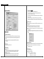
Password setup
Password setup
When SPR Smart View Restart Window appears, select [OK] button to restart the system.
[Notice]
When you try to connect to DVR from SPR Smart Viewer(Remote), SPR Smart View(DVR)
checks the site code and password together.
Network Port Setting
: Network ports used for View-Viewer commnunication must be the same on the both sided.
Site’s network ports can be assigned here.
Description
Password change
: You can assign password to three operators and some functions can be set to work with
permission. (Operator 1 can be in charge of everything and operator 2 and 3 can modify
permitted items only.
Level
: Click Level button to change the each operator’s password.
Old password : Enter current password you are using
New password : Enter new password
Confirm
: Enter new password again
Password Setup
: 1st level administrator can block some mode from 2nd and 3rd level administrator.
The function will be activated by ticking on that box.
[Notice]
If you lose your password, pleas delete C:\WINNT\dPassword.ini and
3-6
3-7
Environment Setup
8
On-screen Keyboard
On-screen Keyboard Display
Functions
: It enables to enter letters using on-screen keyboard when there is no separate keyboard os it
diffcult to use keyboard.
Description
Search Screen
Active On-Screen Keybaord
: Select on-screen keyboard to enter letters, and you can run on-screen keyboard.
Input
: Click he parts to enter the letters among the setting items by a mouse and immediately, press
the letters(keyboard). And you can enter the letters.
Close On-Screen Keyboard
: Select [File]->[Close] menu on On-Screen keyboard or press Close[X] button, and On-screen
Keyboard is closed and the setting window of SPR Smart View program is displayed.
[Notice]
• On-Screen keyboard of SPR Smart View program only provides English and does not support
Korean or other languages.
3-8
4
Search Screen
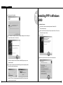
1
2
Run Search Program
Click on search
button to execute from surveillance screen.
Search Date and Time Selection
Calendar
Search ‘Date’
Password screen will appear for securing purpose Click [OK] if the password was not
: Choose the Date you wish to search
initially entered
<< : It shows whole calendar
Search Screen
Search Window
>> : Calendar shows the following month
Convert to
surveillance mode
Calendar
On calendar, it will be indicated in yellow if
anything is recorded on such date, red
indication means the one you clicked to
search, and sky blue indicates that
something is being recorded.
Time indication and Expansion of graph region
Function
Time indication and expansion of Graph region
: It indicates time for the part where data is recorded.
When you click on time, time zone will be expanded in three steps so graph region can
been seen more clearly.
In case such country is applied with Summer Time, color will convert from Yellow (default
color) to pink but it will convert back to Yellow as soon as the Summer Time is over.
Button Camera
Scroll for
Camera
Record
Storage
Time indication and
Expansion for graph
area
Screen division
Configuaton of Search Screen
Search screen Window
Calendar which shows recording date
Time display & expansion of graph section
Function button for search
Switch to monitoring mode
Split screen setting button
Scroll and Camera button to select a camera to search
Graph indicating the type of recording & storage by tme zone
4-1
Any modification of time caused by Summer Time will automatically change back to current
(actual) time.
[Tip] What is Summer Time...
Sun rises early but sets late during summer so people tend to take advantage for this longest
period of daytime of the year by forwarding one hour which is known as Summer Time. Summer
time is widely used throughout the world and people forward one hour earlier than actual time at
the beginning and do the vice-versa at the end of Summer Time. For example, if the starting time
is 2 o’clock then you are to change the time to 3 o’clock and then change 3 o’clock back to 2 at
the end.
4-2
Search Screen
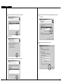
3
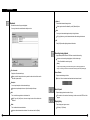
Camera Selection
Camera Selection Screen
4
Playing Recording
Playback
: Select the date, time and camera number to playback.
Adjust search speed and delay to display as you want.
Backward Play
Forward Play
Stop
Play one picture backward
Go to the first one hour of the retrieved image
Description
Play one picture forward
Camera Scroll button
Go to the last one hour of the retrieved image
: This function is to scroll search button from up and down.
Camera
Search Tools
: Choose the camera number you wish to search
Panorama
When you double click on camera number, button and the colored graph of appropriate
camera number will be changed.
:Display selected camera’s image consecutively in each divided screen.
Zoom
: Zoom in and out. Gives five times magnification.
Indication of stored amount
: It indicates record type and storage amount by time.
Violet
Recorded with continuous recording
Blue
Recorded with motion recording
Orange
Recorded with Sensor recording
Green
Recorded with Pre Alarm, but there is no
indication if nothing was recorded
Digital Zoom
: Each click on Digital Zoom button converts among zoom-in / zoom-out / drag.
Zoom-in (+)
: Right click on certain spot zoom in up to 13 grades.
Zoom-out(-)
: Right click on certain spot zoom out.
Drag
: Move the magnified image by dragging
In the search mode zoom in or out is enabled only when one camera is selected.
Search Bar
(Zooming is not possible while playing multiple cameras’ image. Therefore, click ‘stop’
: This function indicates current time line of data which is being searched.
and play One camera to zoom.)
You can immediately search for any recorded data by horizontally moving search bar.
[Note] Black screen will be displayed if there is no image for the camera you selected.
4-3
4-4
Search Screen
Delete all
Bookmark
: Records the location of image under playback
: Delete all the bookmarked image location.
All the image location will be deleted if you click [Delete all] button.
You can go back to the recorded location directly next time.
Goto
: You can go to bookmarked image location by clicking this button.
Click [goto] button to go to the bookmarked location after selecting the bookmark.
OK
: Select [OK] button after adjusting bookmark information.
Recording during playback
: Image search speed will increase if DVR does not record while searching.
In order to set it as recording during playback, click this button again.
(This will be disabled in monitoring mode.)
[Notice]
Though the image recording goes on while searching, however, recording graph does not
change. You should go to live mode and come back to searching mode to see updated graph.
Time Information
: Display time of bookmarked image.
When you add the image location during search the date and time will be saved in
the order by date and time.
Screen Division
: Playback recorded image in division.
4ch, 9ch, 16ch can be selected and deactivated mode cannot be used.
Description
: You can input description on the bookmarked image.
If you do not input description the one in [time Information] will be input.
Add
: This is to add the image location to the bookmark list.
[Add] If you click [Add] button, the current image location will be added to the
bookmark.
Delete
: This is to delete the bookmarked location.
Search Speed
: Playback skipping the certain number of image.
The number is not the number of actual image, but the one set inside SPR Smart View
program.
Display Delay
: Time to display one image on screen.
0 (Fastest) ~ 50 (Slowest)
In order to delete bookmarked record select it in the bookmark and click [Delete]
4-4
4-4
Search Screen
5
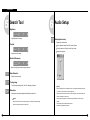
Search Tool
Brightness
: Adjust brightness of the image.
Contrast
6
Audio Setup
Audio playback setup
: Playback with recorded audio.
Click on left button creates “Audio Play” window as below.
Tick on the box next to “Enable” in “Audio Play” window.
Adjust volume properly.
: Adjust contrast of the image.
Smooth & Sharpness
: Make the rough image smooth and vague image clear.
Noise Reduction
: Reduce noise in the image.
Turning image
: Turn the image in the angle of 90, 180 or 270. And flipping is possible.
[Notice]
• Audio can be played only on one selected channel. You cannot play audio watching more than
Restoration
: Getting back to the original image before modification by search tools.
2 channels. You should choose one channel to play audio.
• Video loss can take place within the first 1~3 seconds of play back, this is due to the video and
audio synchronization and is not a fault
[Notice]
Search tools an be used for one camera’s image only. Therefore, you should click stop
button and choose one image to use above tools.
4-5
• Audio can only be played back in normal forward play. Reverse Play or Frame Play is not
possible
• Skip and delay cannot be used with audio play back.
• Please refer to [Appendix] for audio setup.
4-6
Search Screen
7
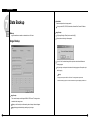
Data Backup
Select Media
: Select backup data from its storage media.
You may select HDD, CD-RW, Portable drive, Network Drive, Remote IP Address
Backup
: copy restored data onto media on a selected time or AVI format.
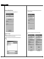
Image Backup
Click [Image Backup] in ”Backup” window and click [OK]
Below ‘watermark checking’ window appears.
Image Backup
If you click ‘Yes’, the selected image will be copied onto media drive with Watermark
checking program.
Only one image can be copied and ‘watermark’ checking program will be copied only at
the first copying.
[Notice]
The image will be copied in BMP or JPG format. The image will be copied with the
‘watermark checker program’ to check to see whether the image was illegally modified or not.
Image Backup
: This is used to backup one still image in BMP or JPEG format. This image can be
viewed with other image viewer.
When you click ’backup’ icon while searching above ’backup’ window will appear.
Image backup gets activated during searching only one image.
4-7
4-7
Search Screen
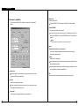
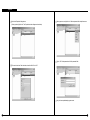
[ How to use Watermark Checker ]
: You can check the authentication of the image restored in BMP or JPG.
Watermark Check Program
Search Screen
When you open the file name, a window below will appear. Select ‘watermark
check’ to verify the image.
Once verification is completed windows similar to those below will appear.
If you execute ‘WMChecker.exe’ which is copied to the media drive with the backup
image, following ‘WaterMark’ checking program appears.
If you click ‘File Open’ button, below widow will appear to check an authentication of the
image
< Corrupted image >
4-7
< Uncorrupted image >
4-7
Search Screen
Time backup (Large Media)
: This is a backup using HDD, CD-RW, mobile driver, network driver or copy using IP
address.
Select media
: Media to use on backup.
You may select HDD, CD-RW, Portable drive, Network Drive, Remote IP Address.
Format CDR/CDRW
: This is used when you select CD to backup data.
If CD was not formatted, use Direct CD program for CD formatting process. When you
select [Format CDR/CDRW], you can format CDR/CDRW media by Direct CD (Refer to
appendix)
[Notice]
Direct CD program has to be installed in window in order to format CD.
Option
[Delete old data when there is not enough space]
: This function will record data after deleting the old data when there is not enough
storage space to backup the data.
[Priority]
: Select the priority of backup data.
Wait until the processing work is done; start the backup after current backup and waiting
data have finished their backup.
Start after the precedent backup; when current data’s backup is completed, do not back
up the waiting data if the other data was selected first.
Backup by time
This streaming data is our own data type. So this image cannot be read using other
OK
program than SPR Smart Viewer program.
: Backup will start from the designated backup media drive when you click [OK].
Date/Time
: Select the time to start and finish backup.
This time setup should be earlier than current time. If this is later than current time
backup does not work despite clicking [OK]
Calculate Size
: Click this button to calculate expected data size for the selected time.
4-7
4-7
Search Screen
[ Backup onto CD-R / CD-RW ]
AVI backup
: converts compressed streaming data into AVI format so that windows media player
can placyback the backup data.
CD-R/RW backup
• Select [Select media] from “backup media“ window.
• From “Select backup media“ window, select [OK] button after selecting CD-RW drive which
you will backup.
• You need to format CD in order to backup CD-R/CD-RW from SPR Smart View program.
• When the CD is unformatted or failed to Backup, please follow this step to Format the CD.
(Refer to appendix)
• In order to backup on CD-R/CD-RW, Direct CD S/W should be installed on the system.
• If the CD is formatted, follow the same way with backup to HDD, or removable drives (DVDRAM, ZIP, MOD, RB)
AVI backup
Data backup is available to HDD, CD-RW, mobile drive, network drive and remote drive
using IP address.
Backup by camera is available during backup in AVI format, and backup of Max. 5 min
video per one time is possible.
Date/Time
In case of backup into AVI, the time between start and end of backup is automatically set to
Max. 5 mins.
Camera
: select the camera number to backup in AVI.
Multiple cameras can be selected and recorded in AVI.
4-7
4-7
Search Screen
[AVI Backup Status]
Select Compressor
: You can select available compression codec under AVI backup.
[Tip]
• In order to format CD, DNE should have Direct-CD installed.
• When other advanced compression codecs then the basic Mpeg compression codec provided on
Window were installed, AVI files are saved into smaller sizes, the compression quality is
advanced and the time for backup is reduced.
Started
• According to types of compression codecs, number of selected cameras and set backup time,
AVI backup time may differ significantly.(When the basic codec provided on Window is used,
codecs of Mpeg4 Video Codec v2 over are recommended.)
• In case of backup into AVI files, audio data are not backed up but only video data are backed up
: When you double click on animated icon
located on top of image while real time is
in progress, current backup data and backup status and its progress rate, lapsed time,
and remained time can be checked.
into AVI files.
• According to the resolution of saved video data, resolutions of AVI files into which the data are
backed up are as follows.
SPR Smart View Resolution
[AVI Real Time Backup File]
AVI File( NTSC / PAL )
640x480(768x576)
320x240(384x288)
160x120(192x144)
320x240
160x120
Select media
: Select media type
HDD, CD-RW, Mobile Driver, or Network driver can be used.
Format CDR/CDRW
: This is used when backup media is CD.
When CD is not formatted a user should proceed CD format using Direct CD program, and
Choose AVI Real Time backup file
once he chooses [Format CDR/CDRW], Direct CD program begins to format CDR/CDRW
: In order to check AVI Real time backup file, double click on recorded file from assigned
media. (refer to appendix)
drive “SDB\BACKUP_AVI\ {xxxxxxxx-xxxx-xxxx-xxxx-xxxxxxxxxxxx} month day yeartime min second ~month day year-time min second[camera No].avi” then you can check
4-7
[Notice]
appropriate file information using
In order to format CD, DNE should have Direct-CD installed.
Window Media Player which is separately provided by real time player or window.
4-7
Search Screen
8
Print Search Screen
Print
: You can only print when Print button is selected from searched screen while
one image is magnified, then click on [OK] button shown below (Size and
Brightness must be adjusted in advance).
Following ERROR will occur if print setup is not completed
AVI Real Time Backup File and Caption information
: Using media player provided from Window, caption information of Date and time, days,
camera number and etc can be indicated. Other real time player shows image only.
[Note]
We recommend minimum of v6.4 for Media Player and if caption information cannot be checked,
then choose ‘Caption’ from [View] to check such information.
4-7
4-8
Search Screen
[Tip]
Print Setup
1. Click Start
Setup
Print from Windows
2. Double click on ’Add Printer’ when Print Menu appears
3. Click [Next] when Add Pinter Wizard executes
4. Check to see if [Local Printer] is selected and then Click [Next] if Printer is connected
to system.
9
Motion Search
Motion Search
: It is used to search only the motion in a specific area while one screen is enlarged among
the search images.
5. Select Print Driver from the box where it asks manufacturer, name, and model of
printer.
6. Print setup is completed when Driver is installed on screen.
Size of Image Output
1. It produces output and the printed size is equivalent to the magnified ones seen
from the screen.
When printer is not working,
1. Check to see whether printer is setup from Window or not
2. If the printer is setup to the system but still not working, then check to see if cable
or power code are connected.
Camera Selection
: Select the camera to search.
The search in part in available only when one channel is enlarged. Then, you can
select only channel for the camera.
4-8
4-9
Search Screen
Designation of a Part to Search
: Designate the part to search on the screen.
Stop Graph Display
: Stop the display of a graph and extraction of data related to motions.
To search the changed image in a specific area of the selected camera, it is required to
If you select [Stop] button while data related to motions on the selected part is searched,
designate the part of the image to search.
only the graph of searchred data is displayed in the graph part.
Display tje graph of the searched data in a seleced part.
: If the data search related to the motions is completed, the yellow graph of the searched data
is overlapped on the exiting graph this is previously saved.
To search the changed image in a specific area of the selected camera, it is required to
designate the part of the image to search.
Time Selection
: Select the starting time and Ending Time to search a specific area of the selected camera.
Graph for the searched data in a selected part.
Selecting time is to display the graph of the data related to the motion detected in the
selected part of the image.
Start the search of a selected part
[Notice]
: Search the data graph of a selected part by time setting and area setting of a selected camera.
If many motions are dectected in the selected part from 00 to 24, it may take long to
Select the displayed graph of a selected part and press Play button, and you can immediately
extract the data on that part. Therefore, it is recommanded to select thetme zone to
search only the images on the parts where the motions are detected.
search.
Display of graph in a Designated Part
: Display the graph of the data related to the motions detected in he designated part of he
selected camera during the selected time.
When you select the graph display button, the processing screen is displayed while the data
[Notice]
The minimum unit for the display on a graph is one minute. And the squential data is displayed.
However, during the actual search, the data may not be sequential according to the recording
by motions.
the motion is extracted.
4-9
4-9
Appendix
5
Appendix
1
Formatting a CD using
Direct CD
When you see a “drive format“ window, input a name to “Label“ and click [Start
Format] button
[Formatting CD using Direct CD]
When you try to backup on an unformatted CD or in case where the message of backup failure
has shown, format the CD as follows.
Below contents is based on Direct CD v5.1. If some other message comes up, please refer
to Direct CD manual.
CD format and backup
Select [Media Select] button in “Backup Media“ -> Select CD-R/RW drive in “Local Drive“
-> Click [OK]
Insert empty CD-R/RW media and click [Format CDR/CDRW]
(If CD-R/RW drive is set as “auto“ Direct CD program will run automatically.)
Check if CD-R/RW is selected when the Direct CD format utility comes up, Direct CD and
“Formatting CD..” Window will appear and starts CD-R/RW media format.
click [format CD]
When the format is done, below window will appear saying “CD Ready“. Then click [OK]
5-1
5-1
Appendix
If Direct CD format utility windows come up, click this button
to close.
( Do not click [eject] button.)
”Direct CD Eject Options” window comes up, select “Close to Read on Any
Computer” and click “OK” (If possible select “Protect CD so it cannot be written to
again” not to re-write on CD-RW)
Select the type, time, and camera for backup and click [OK] button.
“WRITE“ LED of CD-R/RW will be turned on till CD writing is done.
Below window will appear to close CD-R/RW media. Wait until this procedure ends.
Do not press button in CD-R/RW
Once the backup is done, click “Eject” button in CD-R/RW
Once the above procedure ends below window will appear.
Then eject the CD-R/RW media and click [OK] button.
5-1
5-1
Appendix
2
Formatting a CD using InCD
• Set the CD name.
(If you do not want to define the CD name, simply do not enter the name. After entering
the CD name, click on the “Finish” button.)
[Formatting CD using InCD]
• When trying to back up date in an unformatted CD or receiving an error message after
trying to backup up, format the CD by the following procedure.
• insert a black CD, and click on “Format CDR/CDRW” from “Data Backup” window.
Then, the following screen will appear. Click on the “Next” button.
• Drive selection window will appear. Click on the “Next” button.
5-2
5-2
Appendix
• After the CD is completely formatted, the following window will appear.
(Click on the “Confirm” button to complete formatting.)
3
Serial cable connection (input)
ON OFF
1234
• After the CD is completely formatted, continue backup by the same method as those of the
hard disk or movable drives (DVD-RAM, ZIP, MOD, ORB, etc.)
Connect to COM 1
Port
(9 PIN)
RS-232C Port
• If a different message from the above i displayed, refer to InCD manual.
[Notice]
• To format a CD using InCD S/W, only CD-RW media shall be used. It is impossible to
format CD-R media using InCD S/W.
• The operating method and the setting screen differ by InCD S/W versions.
[Function of RS-232 Serial connection]
• Enables Sensor function
• Enables Control function
• Enables P/T/Z function
• Enables Watch Dog function
• Enables External monitor output function (Depends on model)
[Notice]
Serial Cable must appropriately connected to COM1 Port and RS-232 in order to use the function
above.
Control and Sensor, part of the product which is not supported by P/T/Z may not include Serial
Cable. Connection will be provided only for the product that supports control and sensor.
If Serial Cable is not connected appropriately, system may not operate properly and even damage
the system. Also, it may not recovered automatically.
(Product which is not supported by Control and Sensor, P/T/Z function uses its own auto recovery
function.)
5-2
5-3
Appendix
4
PAN/TILT Drive connection
5
External Sensor input and
Control output connection
ON OFF
1234
One line of signal line for sensors such as infrared rays, heat perception, magnetic etc, should
be connected to COM connector and the other line is connected to any sensor 1-8 connector
[I/O Board]
which you selected.
[Notice]
Please use individual adapter for each sensor’s power input.
SIGNAL (+)
EXTERNAL MONITOR
RS-422 connection
(from RX-Receiver)
RS-232 Connection
(from Com1 port)
No Use
SIGNAL (-)
Alarm, Siren, relay etc.
External Power (DC 12V)
• When the linked connection and control by external sensor works linked control output
[Notice]
• Be cautious about (+),(-) of the signal line.
Wrong connection of the signal line might cause damage.
• Please contact our distributor if you use other brand’s RX Receiver.
• The communication distance of the RS-422 connection cable is 1.2Km. (The distance
can vary according to the type of cable connected. The Twist 2C cable is recommended.)
connects to COM port. (setup->hardware->alarm) Control output related by external sensor
it remains “NC” condition normally
but it switches to “NO” when it starts sending control signal
[Notice]
The power of adapter should be no more than 12V and 300mA.
[Note]
• For the SPR-7116 Model, the external monitor connector on IO board is not operational, The
external monitor connector on display board must be used.
5-4
Additional external relay should be used to control on and off of device powered by AC input.
5-5
Appendix
6 Install WebDVR
Click on “Next” button.
Insert the SPR Smart View CD into the CD-ROM and duble-click on the folder where the
SPR Smart View program is saved. When the following window appears, double-click
on Disk1 folder.
Check in “I accept this License Agreement” filed, and click on “Next” button.
Select “Setup”
(If CD-R/RW drive is set as “auto“ Direct CD program will run automatically.)
Select the path to install the SPR Smart View program, and click on “Next” button.
5-6
5-6
Appendix
The program will be installed.
7
Installing PPP in Windows
2000
Installation Procedure
In most cases, a modem is automatically installed in Windows 2000.
(See the modem manual.)
Select “Control Panel” and “Network or Dial-up Connection” folder. Then, click on
“Create New Connection” folder.
Click on “Next”
After “Installation is completed sucessfully” message is displayed, check in “Restart your
computer” field and click on “Finish” button.
Select “Dial-up private network” and click on Next as shown below:
If “Restart your computer” field is not checked, the WebDVR program may not be
completely installed.
The computer will be rebooted, and the WebDVR program will be completely installed
before the user starts to run the program.
Apache HTTP server is to automatically started with the SPR Smart Viewe when the
computer is computer is rebooted.
5-6
5-7
Appendix
Select the modem installed in the system, and click on “Next”.
Select “Internet Protocol (TCP/IP)” from networking components list, and click
on “Properties”.
Click on “Next”.
Make a setting as shown below, and click on “OK”
Select one of allowed users as a guest, and click on “Next”.
5-7
5-7
Appendix
Click on “Finish”.
8
Setting Guest user, Password, and
Account Options
Setting Account Passwords and Options
Select Control Panel, and double-click on “User and Password”. When the following window
appears, select “Advanced” tab:
Then, change the guest user as well as the password and the account.
(For more information about setting the account, see “Changing Guest User’s Password”
in “Appendix”. )
Click on “Advanced” button in the following window:
5-7
5-8
Appendix
Select to view Properties of the guest user.
Select a guest user, and right-click on it. Select set password from the pull-down menu.
(Select a guest and right-click on it. Then, Propertices window will appear as shown below.)
Type in “1234” in New password and Confirm password fields.
If “Account is locked out “ field is checked, uncheck this field. Click on “OK”.
Now, you have completed setting a guest account.
5-8
5-8
Appendix
9
SSC-2000 system keyboard
Camera lens related keys
- IRIS control (IRIS CLOSE / OPEN)
SSC-2000 System Keyboard is the controller to control the DVR by using a RS-485.
- FOCUS control (FOCUS NEAR / FAR)
The user can operate a DVR conveniently as the user friendly on screen display, touch screen and
- ZOOM control (ZOOM TELE / WIDE)
joy stick are applied to the system. (SSC-2000 available Rev. NO : Ver 1.5 or Higher)
MENU KEY
: This is used to return to Menu mode in order to set each device.
Control Device selection keys (MON/CAM/MUX/DVR)
: This is used to designate Camera, Monitor, DVR, MUX Number etc.
Numeric key (0~9), ENTER key, CLEAR key
: This is used to designate Camera, monitor, DVR, MUX Number, Preset, Pattern Number etc.
DVR Control keys (SEQUENCE, MODE)
- SEQUENCE : If you select SEQUENCE button after changing over by 4 and 9 division
mode from the monitoring screen, the division screen shall be changed over
in sequence.
JOG/SHUTTLE
: When controlling the DVR, this enables to search the recorded picture of the desired time
zone by moving the search bar left/right from the DVR search screen.
DVR Reproduction related keys
: When searching the recorded picture from DVR search screen, this is used to move the
picture to the very first line or last line, or reproduce it in clockwise direction or stop it.
Description
move to the first data of the selected date
LCD Display
stop
: This displays the active status of system keyboard.
Camera action related keys
- PRESET
- SCAN
reproduction in clockwise direction/pause
- PATTERN
move to the last data of the selected date
- AUTO PAN
Alarm release key
: This function is to force to stop the alarm output when an alarm sounds in DVR.
Joystick Controller (UP/DOWN/LEFT/RIGHT/AF)
: This function is used to move the action of Pan/Tilt connected to SAMSUNG Dome
Camera or Receiver unit up/down/left/right and control the action of Auto Focus. In
[Notice]
-. Connect SCC-200 through the terminal of RS-485 or RS-422 in the rear of DVR.
-. Connect the signal(+) of the terminal of DVR RS-485 or RS-422 to Tx(+) of SSC-2000.
-. Connect the signal(-) of the terminal of DVR RS-485 or RS-422 to Tx(-) of SSC-2000.
-. For further information of SSC-2000, please refer to User s Manual of SSC-2000.
addition, this is used to control the action of Zoom by turning it clockwise or
counterclockwise.
(When controlling the DVR, this can be used as a mouse to select the menu displayed on
the screen.)
5-9
5-9
Appendix
10
DVR CONTROL BY
SSC-2000 KEYBOARD
1. After selecting [DVR] button from SSC-2000 system keyboard, enter DVR No. (0~255)
of SPR Smart View which is interlocked with SSC-2000 keyboard by using the numeric
keys and then press [ENTER] button.
16 division screen
: If you select [16div] button from the surveillance screen, the screen shall be changed over to 16 division
screen.
Sequence changeover
: If you select [Rotate] button from 4 division or 9 division mode, the screen shall be changed to the
selected division mode in sequence.
DVR Control Screen (Surveillance mode)
Search mode changeover
: If you select [Search] button, the password input screen shall be displayed from SPR Smart View
4div.
Search
9div.
Emergency Rec
16div.
Alarm Off
0 0 1
SPR-7116
0 0 0
screen.
Enter the password from the password input screen and select [OK] button, the screen shall be changed
over to the search mode screen.
Emergency Recording
: When the emergent recording is needed while monitoring, if you select [Emergency Rec] button, you
can record all cameras regardless of the schedule. If you want to release the recording, select
Rotate
[Emergency Rec] button again and enter the password from the password input screen and then select
[OK] button.
Alarm release
: This function is to force to stop the alarm output, when an alarm sounds in DVR.
Environment Setting
: If you select [
] button to set the system, the password input screen shall be displayed for the
system security.If you enter the password from the password input screen and select [OK] button, the
Configuration of Control Screen
DVR No.
screen shall be changed over to the system setting screen.And LCD screen of SSC-2000 keyboard
shall be changed over to the screen as below.
: This displays the no. of DVR connected to SSC-2000.
Model No.
: This displays the model no. of DVR connected to SSC-2000.
Monitor No.
: This displays the no. of monitor connected to SSC-2000. This is not used when controlling
the DVR.
4 division screen
: If you select [4div] button from the surveillance screen, the screen shall be changed
over to 4 division screen.
For direction button or [ENTER] button, you can use the direction button and [ENTER] button or Joystick of SCC-
9 division screen
2000 keyboard by moving them up/down/left/right and even use AF (Auto Focus) button.
: If you select [9div] button from the surveillance screen, the screen shall be changed
If you select [
] button, the screen shall be changed over to DVR control screen.
over to 9 division screen.
5-10
5-10
Appendix
DVR Control Screen (Search mode)
Channel selection
: If you select [
] button, the screen shown as below shall be displayed.
If you select camera button, the picture of the selected camera shall be displayed on the screen
in full size from SPR Smart View screen. If you select the selected camera button again, the screen
shall return to the previous screen.
If you select [
4div.
Zoom
0 0 1
SPR-7116
9div.
] button, the screen shall be changed over to DVR control screen.
0 0 0
16div.
0 0 1
SPR-7116
Panorama
0 0 0
DVR control mode close
: If you select [
] button, you can exit from the DVR control DVR.
Configuration of Control Screen
4 division screen
: If you select [4div] button from the surveillance screen, the search camera shall be selected by
4 channel unit.
9 division screen
: If you select [9div] button from the surveillance screen, the search camera shall be selected by
9 channel unit.
16 division screen
: you select [16div] button from the surveillance screen, the search camera shall be selected by
16 channel unit.
Panorama
: When you search the picture after selecting one camera, this function shows the selected pictures
on each division mode in sequence.
Zoom
: If you select [Zoom] button, the captured pictures can be enlarged or reduced. In addition, this
function provides 5 steps of picture enlargement.
5-10
5-10
Appendix
Channel selection
: If you select [
] button, the screen shown as below shall be displayed.
You can select the desired camera or search among no. 1~16 cameras.
If you select [
] button, the screen shall be changed over to DVR control screen.
11
External monitor 2 output quality
control
When using an external monitor over a long distance the quality of the picture can be
reduced, also the picture might shake or have some interference. This is because the
power of the signal can drop over a long distance.
0 0 1
SPR-7116
To overcome this problem you can use the control switch on the back panel of the DVR
0 0 0
<SPR-7116 Model>
ON OFF
1234
DVR control mode close
: If you select [
] button, you can exit from the DVR control DVR.
[Display Board]
External monitor 2
ON OFF
1234
External monitor output
Control switch
Spot monitor 1
1234
ON OFF
S-VIDEO Connection
[Warning]
External monitor setup function only can be applied to external
moniter output 2, not external monitor output 1.
5-10
5-11
Appendix
<SPR-7416 Model>
ON OFF
1234
[Display Board]
External monitor
ON OFF
ON OFF
1234
1234
External monitor output
Control switch
The distance between the DVR and external monitor should be measured then you can change the
control switch on the back of the DVR accordingly. There are 4 level settings for the difference distances
between DVR and Monitor so you can select which gives the best picture.
1
For 100 meter distance select dip switch setting one.
2
For 200 meter distance select dip switch setting two.
3
For 300 meter distance select dip switch setting three.
4
For 400 meter distance select dip switch setting four.
[Warning]
The set-up must be with only one switch turned on at a time. If the all
switches are turned off there is no signal output to the external monitor.
[Notice]
If the distance is 500m or if the installation environment is not good then the
picture display quality will be reduced.
The distance between 100~400 have been tested but the actual distance can
be changed depending on weather and line condition.
[Notice]
For the SPR-7116 Model, the external monitor connector on IO board is not
operational, The external monitor connector on display board must be used.
5-11
Specification
Specification
1
Specification
Main Spec.
• CPU
Display Speed
: Intel P-IV 2.8Ghz (Depends on the user)
• Main Memory : DDR 512MB
• VGA
: ATI (128MB)
• HDD
: 250GB
• O/S
: Windows 2000 Professional
• LAN
: Realtek 10/100 MB
Video Input
• 16Ch Composite Video (NTSC/PAL)
Video Output
• 1, 4, 6, 9, 16 split screen, full screen
SPR-7416 : 480 Frames/sec, 16Ch Monitors Real time, 480 Frames/sec Recording Real time
• 1, 4, 9, 16 split screen, full screen
SPR-7116 : 480 Frames/sec, 16Ch Monitors Real time, 120 Frame/sec Recording
Alarm Output
• Output from 16 NI/NO
Motion Detection
Camera/Sensor
• Output from PC and normal monitor SPOT
Pan/Tilt/Zoom Control
Recording Speed
• SPR-7116 : Max 120 Frames/sec
Transmission speed
• PSTN : 1~5 Frames/sec, LAN : 30 Frames/sec (Max), ISDN : 3~10 Frames/sec
• SPR-7416 : Max 480 Frames/sec
Back Up
Compression Method : Modified H.263
Compression Rate : Ave. 2.5KB/F (320x240)
Auto Switching
• 1~10 sec
Configuration and size
• Product : 431(W) x 177(H) x 459(D)
Power :
Playback Display Mode
• Domestic : AC100-240V~, 5Amax, 60Hz
• Simultaneously reproduce each channel from 4, 9, 16 split screen
• U.S/Europe : AC100-120/200-240V~, 5/3A, 50-60Hz
Sensor Input
• Input 16ch
6-1
• Auto/Manual Back up through CD-RW, DVD, Network Drive
Weight : SPR-7116 : 18kg
SPR-7416 : 18.5kg
6-1
Q&A
7
Q&A
The system is not powered on and LED status indicator is not operated.
The system is rebooted every 10 minutes.
Check if the power is connected properly.
Check if the Serial Port connection cable connecting COM1 port to I/O Card, is sticking
Check the voltage of power supply.
in the back of the system.
If the power is not on after checking the two items above, then inspect or replace the
SPR Smart View system has the function that reboots the system every 10 minutes
power supply.
when Serial Port is not connected, for the safety of the system.
LED status indicator is operated and the beep sound is heard but, monitor
The video is input but some of the channels is not output and blue screen
screen is not output.
appears.
Please check if the monitor power cable is connected exactly to the connection cable.
Check if there is something wrong in the video of relevant camera number connected to
This kind of condition may occur when the contact condition of the monitor connection
the system. This kind of condition may occur when video of camera is not input properly.
cable connected to the VGA card is not good.
Be sure that the power is supplied to the camera normally.
Check again if the video line connected with the camera and SPR Smart View system.
When the system is turned on, window is not executed while the message, “Verifying
This kind of condition may occur when the video signal which is output from the
DMI Pool Data…“ or “Invalid system disk, Replace the disk,..“ is output.
VDA(Video Distributing Amplifire) is weak while the video is connected to the several
The window may not be executed and the message is output while a part or entire of
systems.
system file is damaged in the drive that the window is installed.
By connecting the video of the relevant camera to the SPR Smart View system, you
Please consult to the place you bought the system and replace HDD.
The system is rebooted automatically while SPR Smart View program is
executed.
can confirm/solve the causes of the problem.
The tone of color or video from some of the cameras appears abnormal.
Check if there is something wrong in the video of relevant camera number connected to
That is the normal function of the computer.
the system.
“Display Set-up Restoration Function” is one of the functions included in the SPR Smart
Check the problems of the camera or SPR Smart View system, by inputting the number
View product. In case the display adapter installed in windows system is not properly set
of damaged camera and of normally output camera alternatively.
up, it reboot the system automatically by changing the set-up.
Check the type of the camera.
The video type of the camera includes PAL mode, NTSC mode and SECAM mode
The system is rebooted early in the morning, periodically.
according to each countries standard and the video process methods varies based on
That is the normal function of the computer.
video transmitting methods of each camera. In this case, you will have a difficulty in
You can set up the option in SPR Smart View Program to reboot automatically at a
distinguishing the video properly. Be sure that video type of the camera and setup-
certain time for the safety of the system. The restart time can be changed in the “system
system-the others-video format” item is in accord.
restart time” item which is shown by selecting “set-up” button and “system” tab.
(It is set up as 03:00 am basically at the time of product delivery.)
7-1
7-1
Warranty Guide
This product has passed thorough quality control and test, and if this get broken during normal use we provide
12 months warranty service.
Warranty Guide
Check this warranty sheet first.
Please contact the distributor after checking out any defect in the product.
The standard for repairing, replacement or reimbursement follows Customer
Warranty Content
Any defect under normal use within the warranty service period we give you free repair service
according to the warranty sheet.
We charge you with the fee of parts and service despite free warranty service period.
1. Any breakage made without care.
2. Breakage or trouble made by natural disaster.
3. Breakage or trouble made by breaking the product guide or manual.
4. Breakage or trouble made by wrong power voltage or frequency.
5. When you want to reassemble for full system or replace parts within warranty service period.
6. When unauthorized engineer modified or made damage on the product trying to repair it, we may
charge ] you with the fee.
We don’t support the breakage after warranty service period. If the customer wants to get it repaired,
we charge them with the fee.
ProductWarranty Service Sheet
Product & model name
Product Serial Number
Distributor
Date you purchased
Warranty Period
Name
Customer
Address
1 year from the purchasing date
• This warranty sheet may not be provided again.
• Please get this sheet filled when you purchase the product.
• You should show this warranty service sheet when you get a warranty service.