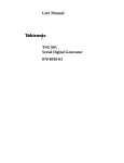
1
IMI CORNELIUS INC g One Cornelius Place g Anoka, MN 55303-6234 Telephone (800) 238-3600 Facsimile (612) 422-3246 Service Manual SELF-CONTAINED FLAKED ICE MAKER Model: Series 200, 525, 725 (R404A Refrigerant) IMPORTANT: TO THE INSTALLER. It is the responsibility of the Installer to ensure that the water supply to the dispensing equipment is provided with protection against backflow by an air gap as defined in ANSI/ASME A112.1.2-1979; or an approved vacuum breaker or other such method as proved effective by test. Water pipe connections and fixtures directly connected to a potable water supply shall be sized, installed, and maintained according to Federal, State, and Local Codes. Distributed By: Commercial Refrigeration Service, Inc. WWW.WorldRestaurantSupply.COM toll free (866) Ice Maker (623) 869-8881 Part No. 166240010 November, 1993 Revised: October, 1996 THIS DOCUMENT CONTAINS IMPORTANT INFORMATION This Manual must be read and understood before installing or operating this equipment IMI CORNELIUS INC; 1993–96 PRINTED IN U.S.A TABLE OF CONTENTS Page INTRODUCTION . . . . . . . . . . . . . . . . . . . . . . . . . . . . . . . . . . . . . . . . . . . . . . . . . . . . . . . . . . . 1 SPECIFICATIONS 200 . . . . . . . . . . . . . . . . . . . . . . . . . . . . . . . . . . . . . . . . . . . . . . . . . . . . . 2 SPECIFICATIONS 525 . . . . . . . . . . . . . . . . . . . . . . . . . . . . . . . . . . . . . . . . . . . . . . . . . . . . . 3 SPECIFICATIONS 725 . . . . . . . . . . . . . . . . . . . . . . . . . . . . . . . . . . . . . . . . . . . . . . . . . . . . . 4 INSTALLATION INSTRUCTIONS . . . . . . . . . . . . . . . . . . . . . . . . . . . . . . . . . . . . . . . . . . . . 5 ADJUSTMENT PROCEDURE . . . . . . . . . . . . . . . . . . . . . . . . . . . . . . . . . . . . . . . . . . . 6 TYPICAL WATER CIRCUIT . . . . . . . . . . . . . . . . . . . . . . . . . . . . . . . . . . . . . . . . . . . . . 7 TYPICAL REFRIGERANT CIRCUIT . . . . . . . . . . . . . . . . . . . . . . . . . . . . . . . . . . . . . . 8 ELECTRICAL CIRCUIT . . . . . . . . . . . . . . . . . . . . . . . . . . . . . . . . . . . . . . . . . . . . . . . . . . . . . 9 CIRCUIT DESCRIPTION . . . . . . . . . . . . . . . . . . . . . . . . . . . . . . . . . . . . . . . . . . . . . . . 9 ON–OFF SWITCH/CIRCUIT BREAKER . . . . . . . . . . . . . . . . . . . . . . . . . . . . . 9 BIN THERMOSTAT . . . . . . . . . . . . . . . . . . . . . . . . . . . . . . . . . . . . . . . . . . . . . . . 9 HIGH PRESSURE CONTROL . . . . . . . . . . . . . . . . . . . . . . . . . . . . . . . . . . . . . . 9 GEARMOTOR START RELAY . . . . . . . . . . . . . . . . . . . . . . . . . . . . . . . . . . . . . 9 POWER RELAY/CONTACTOR . . . . . . . . . . . . . . . . . . . . . . . . . . . . . . . . . . . . . 9 FAN CYCLING SWITCH . . . . . . . . . . . . . . . . . . . . . . . . . . . . . . . . . . . . . . . . . . . 9 DELAY THERMOSTAT . . . . . . . . . . . . . . . . . . . . . . . . . . . . . . . . . . . . . . . . . . . . 9 COMPRESSOR START RELAY . . . . . . . . . . . . . . . . . . . . . . . . . . . . . . . . . . . . 10 POTENTIAL RELAYS . . . . . . . . . . . . . . . . . . . . . . . . . . . . . . . . . . . . . . . . . . . . . 10 CAPACITORS – GENERAL . . . . . . . . . . . . . . . . . . . . . . . . . . . . . . . . . . . . . . . . 10 MAINTENANCE . . . . . . . . . . . . . . . . . . . . . . . . . . . . . . . . . . . . . . . . . . . . . . . . . . . . . . . . . . . 11 SANITIZING AND CLEANING PROCEDURE . . . . . . . . . . . . . . . . . . . . . . . . . . . . . . 12 WATER TREATMENT . . . . . . . . . . . . . . . . . . . . . . . . . . . . . . . . . . . . . . . . . . . . . . . . . . 12 WINTER STORAGE . . . . . . . . . . . . . . . . . . . . . . . . . . . . . . . . . . . . . . . . . . . . . . . . . . . 13 CLEANING THE CONDENSER (AIR COOLED) . . . . . . . . . . . . . . . . . . . . . . . . . . . 13 SERVICE ANALYSIS . . . . . . . . . . . . . . . . . . . . . . . . . . . . . . . . . . . . . . . . . . . . . . . . . . . . . . . 18 UNIT WILL NOT RUN . . . . . . . . . . . . . . . . . . . . . . . . . . . . . . . . . . . . . . . . . . . . . . . . . . 18 COMPRESSOR CYCLES INTERMITTENTLY. . . . . . . . . . . . . . . . . . . . . . . . . . . . . . 18 MAKING WET ICE. . . . . . . . . . . . . . . . . . . . . . . . . . . . . . . . . . . . . . . . . . . . . . . . . . . . . 18 UNIT RUNS BUT MAKES NO ICE. . . . . . . . . . . . . . . . . . . . . . . . . . . . . . . . . . . . . . . . 18 WATER LEAKS. . . . . . . . . . . . . . . . . . . . . . . . . . . . . . . . . . . . . . . . . . . . . . . . . . . . . . . . 19 EXCESSIVE NOISE OR CHATTERING. . . . . . . . . . . . . . . . . . . . . . . . . . . . . . . . . . . 19 MACHINE RUNS WITH FULL BIN OF ICE. . . . . . . . . . . . . . . . . . . . . . . . . . . . . . . . 19 UNIT OFF ON RESET. . . . . . . . . . . . . . . . . . . . . . . . . . . . . . . . . . . . . . . . . . . . . . . . . . 19 UNIT GOES OFF ON RESET. . . . . . . . . . . . . . . . . . . . . . . . . . . . . . . . . . . . . . . . . . . . 19 UNIT GOES OFF ON RESET. (CONT’D) . . . . . . . . . . . . . . . . . . . . . . . . . . . . . . . . . 20 ILLUSTRATED PARTS BREAKDOWN, SERIES 525–725 . . . . . . . . . . . . . . . . . . . . . . 21 PARTS LIST . . . . . . . . . . . . . . . . . . . . . . . . . . . . . . . . . . . . . . . . . . . . . . . . . . . . . . . . . . . . . . 22 CABINET PARTS LIST . . . . . . . . . . . . . . . . . . . . . . . . . . . . . . . . . . . . . . . . . . . . . . . . . . . . . 23 WARRANTY . . . . . . . . . . . . . . . . . . . . . . . . . . . . . . . . . . . . . . . . . . . . . . . . . . . . . . . . . . . . . . 24 i 166240010 TABLE OF CONTENTS (cont’d) LIST OF FIGURES Page FIGURE 1. 200 SERIES SPECIFICATIONS . . . . . . . . . . . . . . . . . . . . . . . . . . . . . . . 2 FIGURE 2. 525 SERIES SPECIFICATIONS . . . . . . . . . . . . . . . . . . . . . . . . . . . . . . 3 FIGURE 3. 725 SERIES SPECIFICATIONS . . . . . . . . . . . . . . . . . . . . . . . . . . . . . . . 4 FIGURE 4. WATER LEVEL ADJUSTMENT PROCEDURE . . . . . . . . . . . . . . . . . . 6 FIGURE 5. TYPICAL WATER CIRCUIT . . . . . . . . . . . . . . . . . . . . . . . . . . . . . . . . . . . 7 FIGURE 6. TYPICAL REFRIGERANT CIRCUIT . . . . . . . . . . . . . . . . . . . . . . . . . . . 8 FIGURE 7. WIRING DIAGRAM AF– 200–P-SC-R 115 VOLTS 60 HZ . . . . . . . . . 14 FIGURE 8. WIRING DIAGRAM AF-200-P-SC-50-R 220 VOLTS 50 HZ . . . . . . . 15 FIGURE 9. WIRING DIAGRAM AF525–SC-R AND AF725-SC-R 115 VOLTS 60 HZ . . . . . . . . . . . . . . . . . . . . . . . . . . . . . . . . . . . . . . . . . . . . . . . . . . . . . . 16 FIGURE 10. WIRING DIAGRAM AF/WF-525PSC-50-R 220 VOLTS 50 HZ . . . . 17 FIGURE 11. PARTS BREAKDOWN . . . . . . . . . . . . . . . . . . . . . . . . . . . . . . . . . . . . . . 21 FIGURE 12. CABINET PARTS BREAKDOWN . . . . . . . . . . . . . . . . . . . . . . . . . . . . . 23 LIST OF TABLES AF-200-P(S)-SCR PRODUCTION CHART . . . . . . . . . . . . . . . . . . . . . . . . . . . . . . . . 2 AF-200-P-SC50R PRODUCTION CHART . . . . . . . . . . . . . . . . . . . . . . . . . . . . . . . . . 2 AF-525-P(S)-SCR PRODUCTION CHART . . . . . . . . . . . . . . . . . . . . . . . . . . . . . . . . 3 AF-525-P-SC50R PRODUCTION CHART . . . . . . . . . . . . . . . . . . . . . . . . . . . . . . . . . 3 AF-725-P-SCR PRODUCTION CHART . . . . . . . . . . . . . . . . . . . . . . . . . . . . . . . . . . . 4 166240010 ii INTRODUCTION We have strived to produce a quality product. The design has been kept simple thus insuring trouble–free operation. This manual has been prepared to assist servicemen and users with information concerning installation, construction and maintenance of the ice making equipment. The problems of the serviceman and user have been given special attention in the development and engineering of our ice makers. If you encounter a problem which is not covered in this manual, please feel free to write or call. We will be happy to assist you in any way we can. When writing, please state the model and serial number of the machine. Address all correspondence to: A Product of IMI Cornelius Inc. One Cornelius Place Anoka, MN 55303–6234 Phone 800–554–3526 FAX 612–422–3232 PRINTED IN USA 1 166240010 SPECIFICATIONS 200 26 1/2-IN. 67-CM 13 1/2-IN. 34-CM 4-IN. 10-CM 7-IN. 18-CM ON-OFF SWITCH 5-IN. 13-CM 34-IN. 86-CM 40-IN. 102-CM REAR VIEW OF CABINET ELECTRICAL BOX AREA B 26-IN. 66-CM 6-IN. 15-CM 3/4-IN. 2-CM A C 19-IN. 48-CM 24 7/8-IN. 63-CM AIR FLOW 25-IN. 64-CM 7-IN. 18-CM A- 1/4 WATER INLETS (S.A.E. MALE FLARE) B- 5/8 O.D. TUBE (DRAIN) C- 1/2 O.D. TUBE (DRAIN) FIGURE 1. 200 SERIES SPECIFICATIONS ÁÁÁÁÁÁÁÁÁÁÁÁÁÁÁÁÁÁÁÁÁÁÁÁÁÁÁÁ ÁÁÁÁÁÁÁÁÁÁÁÁÁÁÁÁÁÁÁÁÁÁÁÁÁÁÁÁ ÁÁÁÁÁÁÁ ÁÁÁÁÁÁÁÁÁÁÁÁÁÁÁÁÁÁÁÁÁÁ ÁÁÁÁÁÁÁÁ ÁÁÁÁÁÁÁÁÁÁÁÁÁÁÁÁ ÁÁÁÁÁÁÁÁÁÁÁÁÁÁÁÁÁÁÁÁÁÁÁÁÁÁÁÁÁÁÁ ÁÁÁÁÁÁÁÁÁÁÁÁÁÁÁÁÁÁÁÁÁÁÁÁÁÁÁÁÁÁÁ ÁÁÁÁÁÁÁÁÁÁÁÁÁÁÁÁÁÁÁÁÁÁÁÁÁÁÁÁÁÁÁ ÁÁÁÁÁÁÁÁÁÁÁÁÁÁÁÁÁÁÁÁÁÁÁÁÁÁÁÁ ÁÁÁÁÁÁÁÁÁÁÁÁÁÁÁÁÁÁÁÁÁÁÁÁÁÁÁÁ ÁÁÁÁÁÁÁ ÁÁÁÁÁÁÁÁÁÁÁÁÁÁÁÁÁÁÁÁÁÁ ÁÁÁÁÁÁÁÁ ÁÁÁÁÁÁÁÁÁÁÁÁÁÁÁÁ ÁÁÁÁÁÁÁÁÁÁÁÁÁÁÁÁÁÁÁÁÁÁÁÁÁÁÁÁÁÁÁ ÁÁÁÁÁÁÁ ÁÁÁÁÁÁÁÁ ÁÁÁÁÁÁÁÁ ÁÁÁÁÁÁÁÁ ÁÁÁÁÁÁÁÁÁÁÁÁÁÁÁÁÁÁÁÁÁÁÁÁÁÁÁÁÁÁÁ ICE PRODUCTION CAPACITY (approximate) AIR TEMPERATURE 50° F/10° C 70° F/21° C 90° F/27° C AIR TEMPERATURE 50° F/10° C 70° F/21° C 90° F/27° C AF-200-P(S)-SCR PRODUCTION CHART WATER TEMPERATURE 50° F/10° C 70° F/21° C 219 lbs/99 kgs 188 lbs/85 kgs 208 lbs/95 kgs 174 lbs/79 kgs 161 lbs/35 kgs 130 lbs/59 kgs 80° F/27° C 175 lbs/79 kgs 166 lbs/75 kgs 117 lbs/53 kgs AF-200-P-SC50R PRODUCTION CHART WATER TEMPERATURE 50° F/10° C 70° F/21° C 234 lbs/106 kgs 206 lbs/94 kgs 213 lbs/97 kgs 190 lbs/86 kgs 183 lbs/83 kgs 164 lbs/75 kgs 80° F/27° C 197 lbs/90 kgs 180 lbs/82 kgs 156 lbs/71 kgs 200 Copeland JS25CIE-IAA-203 (115V 60HZ) Copeland AS13CIE-1AZ-908 (220V 50HZ) Air Cooled 8 oz. R-404a (115V 60HZ) 7 oz. R-404a (220V 50HZ) Automatic Expansion Valve (28-PSI) Automatic Expansion Valve (31-PSI) 1/4” SAE male flare 115V 60HZ or 220V 50HZ 1/8 hp 2 amps (115V 60 HZ) 1 amp (220V 50HZ) 11.0 Amps (115V 60HZ) 4.0 Amps (220V 50HZ) 15 Amp (115V 60HZ) 15 Amp (220V 50HZ) Compressor Model Condenser Refrigerant Charge Refrigerant Control (115V 60HZ) Refrigerant Control (220V 50HZ) Inlet Water Supply Voltage Gearmotor Electrical Rating Gearmotor Amp. Rating Total Amp. Draw Maximum Fuse Size 166240010 2 SPECIFICATIONS 525 26 1/2-IN. 67-CM 13 1/2-IN. 34-CM 2-IN. 5-CM 3 1/2-IN. 9-CM 3 1/2-IN. 9-CM 2 1/2-IN. 6-CM ON-OFF SWITCH 34-IN. 86-CM ELECTRICAL BOX AREA 5 5/8-IN. 14-CM B 26-IN. 66-CM REAR VIEW OF CABINET 5/8-IN. 2-CM A 19 1/2-IN. 50-CM 3 5/8-IN. 9-CM D E 40-IN. 102-CM MIN. C AIR IN 24 3/4-IN. 63-CM 38 3/4-IN. 97-CM 4 5/8-IN. 12-CM 26 3/8-IN. 67-CM 14-IN. 36-CM 6-IN. 15-CM MIN. 3 3/4-IN. 10-CM 3 3/8-IN. 9-CM A- 3/8 WATER INLET (S.A.E. MALE FLARE) B- 1/2 O.D. TUBE (CONDENSATE DRAIN) C- 3/4 N.P.T. BIN DRAIN D- CONDENSER WATER IN (W/C ONLY) E- CONDENSER WATER OUT (W/C ONLY) FIGURE 2. 525 SERIES SPECIFICATIONS ÁÁÁÁÁÁÁÁÁÁÁÁÁÁÁÁÁÁÁÁÁÁÁÁÁÁÁÁ ÁÁÁÁÁÁÁÁÁÁÁÁÁÁÁÁÁÁÁÁÁÁÁÁÁÁÁÁ ÁÁÁÁÁÁÁ ÁÁÁÁÁÁÁÁÁÁÁÁÁÁÁÁÁÁÁÁÁÁ ÁÁÁÁÁÁÁÁ ÁÁÁÁÁÁÁÁÁÁÁÁÁÁÁÁ ÁÁÁÁÁÁÁÁÁÁÁÁÁÁÁÁÁÁÁÁÁÁÁÁÁÁÁÁÁÁÁ ÁÁÁÁÁÁÁ ÁÁÁÁÁÁÁÁ ÁÁÁÁÁÁÁÁ ÁÁÁÁÁÁÁÁ ÁÁÁÁÁÁÁÁÁÁÁÁÁÁÁÁÁÁÁÁÁÁÁÁÁÁÁÁÁÁÁ ÁÁÁÁÁÁÁÁÁÁÁÁÁÁÁÁÁÁÁÁÁÁÁÁÁÁÁÁ ÁÁÁÁÁÁÁ ÁÁÁÁÁÁÁÁÁÁÁÁÁÁÁÁÁÁÁÁÁÁ ÁÁÁÁÁÁÁÁÁÁÁÁÁÁÁÁÁÁÁÁÁÁ ÁÁÁÁÁÁÁÁÁÁÁÁÁÁÁ ÁÁÁÁÁÁÁÁÁÁÁÁÁÁÁÁ ÁÁÁÁÁÁÁÁÁÁÁÁÁÁÁÁÁÁÁÁÁÁÁÁÁÁÁÁÁÁÁ ÁÁÁÁÁÁÁ ÁÁÁÁÁÁÁÁ ÁÁÁÁÁÁÁÁ ÁÁÁÁÁÁÁÁ ÁÁÁÁÁÁÁÁÁÁÁÁÁÁÁÁÁÁÁÁÁÁÁÁÁÁÁÁÁÁÁ ICE PRODUCTION CAPACITY (approximate) AIR TEMPERATURE 50° F/10° C 70° F/21° C 90° F/27° C AIR TEMPERATURE 50° F/10° C 70° F/21° C 90° F/27° C AF-525-P(S)-SCR PRODUCTION CHART WATER TEMPERATURE 50° F/10° C 70° F/21° C 654 lbs/297 kgs 588 lbs/267 kgs 639 lbs/290 kgs 563 lbs/256 kgs 562 lbs/255 kgs 479 lbs/218 kgs 80° F/27° C 552 lbs/251 kgs 521 lbs/237 kgs 448 lbs/204 kgs AF-525-P-SC50R PRODUCTION CHART WATER TEMPERATURE 50° F/10° C 70° F/21° C 629 lbs/286 kgs 528 lbs/240 kgs 621 lbs/282 kgs 525 lbs/239 kgs 493 lbs/224 kgs 414 lbs/188 kgs 80° F/27° C 494 lbs/225 kgs 489 lbs/222 kgs 387 lbs/176 kgs 525 Compressor Model Copeland RS43CIE-IAA-214 (115V 60HZ) Copeland RS43CIE-IAZ-214 (220V 50HZ) Condenser Refrigerant Charge Refrigerant Control Inlet Water Supply Voltage Total Amp Draw Air Cooled 17 oz. R–404a Automatic Expansion Valve (34-PSI) 3/8” SAE Male Flare 115V 60HZ or 220V 50HZ 15.5 Amps (115V 60HZ) 6.0 Amps (220V 50HZ) 2 Amps (115V 60HZ) 1 Amp (220V 50HZ) 1/8 hp 20 Amp (115V 60HZ) 15 Amp (220V 50HZ) Gearmotor Amp Draw Gearmotor Electrical Rating Maximum Fuse Size 3 166240010 SPECIFICATIONS 725 30-IN. 76-CM 17 1/8-IN. 43-CM 2 3/8-IN. 6-CM 2-IN. 5-CM 2 3/4-IN. 7-CM 2 1/2-IN. 6-CM ON-OFF SWITCH 34-IN. 86-CM 40-IN. 102-CM MIN. 26-IN. 66-CM REAR VIEW OF CABINET ELECTRICAL BOX AREA 19 1/2-IN. 50-CM A 5 5/8-IN. 14-CM B D E AIR IN 28 3/8-IN. 72-CM 48-IN. 122-CM 4 1/2-IN. 11-CM 16 3/8-IN. 42-CM 6-IN. 15-CM 5/8-IN. 2-CM 3 1/4-IN. 8-CM C 5 1/32-IN. 13-CM 32 1/16-IN. 81-CM 4-IN. 10-CM A- 3/8 WATER INLET (S.A.E. MALE FLARE) B- 1/2 O.D. TUBE (CONDENSATE DRAIN) C- 3/4 N.P.T. BIN DRAIN D- CONDENSER WATER IN (W/C ONLY) E- CONDENSER WATER OUT (W/C ONLY) FIGURE 3. 725 SERIES SPECIFICATIONS ÁÁÁÁÁÁÁÁÁÁÁÁÁÁÁÁÁÁÁÁÁÁÁÁÁÁÁÁ ÁÁÁÁÁÁÁÁÁÁÁÁÁÁÁÁÁÁÁÁÁÁÁÁÁÁÁÁ ÁÁÁÁÁÁÁ ÁÁÁÁÁÁÁÁÁÁÁÁÁÁÁÁÁÁÁÁÁÁ ÁÁÁÁÁÁÁÁÁÁÁÁÁÁÁÁÁÁÁÁÁÁ ÁÁÁÁÁÁÁÁÁÁÁÁÁÁÁ Á ÁÁÁÁÁÁÁÁÁÁÁÁÁÁÁÁÁÁÁÁÁÁÁ ÁÁÁÁÁÁÁÁÁÁÁÁÁÁÁÁÁÁÁÁÁÁÁÁÁÁÁÁÁÁÁ ÁÁÁÁÁÁÁÁÁÁÁÁÁÁÁÁÁÁÁÁÁÁÁÁÁÁÁÁÁÁÁ ICE PRODUCTION CAPACITY (approximate) AIR TEMPERATURE 50° F/10° C 70° F/21° C 90° F/27° C AF-725-P-SCR PRODUCTION CHART WATER TEMPERATURE 50° F/10° C 70° F/21° C 654 lbs/297 kgs 588 lbs/267 kgs 639 lbs/290 kgs 563 lbs/256 kgs 562 lbs/255 kgs 479 lbs/218 kgs 725 Copeland RS43CIE–IAA–214 Air Cooled 17 oz. R–404a Automatic Expansion Valve (34-PSI) 3/8” SAE Male Flare 115V 60HZ 15.5 Amps 2 Amps 1/8 hp 20 Amp Compressor Model Condenser Refrigerant Charge Refrigerant Control Inlet Water Supply Voltage Total Amp Draw Gearmotor Amp Draw Gearmotor Electrical Rating Maximum Fuse Size 166240010 80° F/27° C 552 lbs/251 kgs 521 lbs/237 kgs 448 lbs/204 kgs 4 INSTALLATION INSTRUCTIONS You will get better service from the ice machine, longer life and greater convenience if you choose its location with care. Here are a few points to consider: 1. Select a location as close as possible to where you are going to use the ice. 2. Allow a minimum of 6” space at sides and rear of machine for ventilation. 3. A kitchen installation is not desirable as a rule. If a kitchen installation is necessary, locate the machine as far away from the cooking area as possible. Grease laden air will form greasy deposits on the condenser. This reduces the ice making efficiency and necessitates thorough cleaning quite often. 4. If you install the unit in a storeroom, be sure the room is well ventilated. NOTE: Do not install where the ambient and incoming water temperature will drop below 50°F or rise to over 100°F. NOTE: If water pressure exceeds 50 lbs., a water pressure regulator should be installed in water inlet line between water shut–off valve and strainer. Minimum incoming water pressure required is 22 lbs.. A. Uncrate the unit by removing the staples or nails from the bottom of the carton and lift off. B. Remove the bolts holding the skid to the machine. C. If legs are used, adjust the leveling legs of the storage bin until the unit is level and all four (4) legs are in solid contact with the floor. Leveling is very important to obtain proper draining. D. Provide a cold water supply line to the area selected for the installation of the unit. The incoming water line should have a shut–off valve provided at a convenient location close to the ice maker. The water strainer provided with the unit should be installed on the down–stream side of the shut–off valve. The supply line must be adequately sized to compensate for the lengths of the incoming water run. The machine is equipped with a 3/8” male flare connection for the incoming water line. NOTE: ALWAYS FLUSH OUT WATER LINES BEFORE STARTING UNIT. Water cooled units have a water regulating valve that is factory set to operate at 270 to 310 PSIG head pressure for R404a (water outlet temp. approx. 105F) This should be checked at the time the unit is being installed. Two water inlet connections are provided on water cooled units, one for the ice making (evaporator) section, the other is for the water cooled condenser. Both connections are 3/8” male flare fittings. Inlet water to the condenser will go to the water regulating valve first, then to the condenser coil and out the drain. The reason for separate water inlet connections is that some installations use a water tower for cooling the water used in the water cooled condenser and some installations use treated water for the ice making inlet water. A separate drain will be required for the outlet of the water cooled condenser. E. Provide a suitable trapped open drain as close as possible to the area where the ice maker is going to be installed. This may be an existing floor or a 1 1/4” trapped open drain. Connect the drain line to the rear of the unit and run it with a good fall to the open drain. All plumbing must be installed according to local codes. The storage bin drains by gravity, and therefore the drain line must maintain a gradual slope to an open drain and should be insulated. NOTE: IN SOME CASES IT MAY BE NECESSARY TO INSULATE THE WATER SUPPLY LINE AND DRAIN LINE. CONDENSATE DRIPPING TO THE FLOOR CAN CAUSE SERIOUS STAINING OF CARPETS OR HARDWOODS. 5 166240010 F. Connect a drain hose to the condensate drain stub tube. NOTE: All plumbing must be done in accordance with national and local codes. G. Connect the electrical supply line to the unit. NOTE: Make sure the proper voltage and number of wires are provided. See serial plate for this information. NOTE: All wiring must conform to national and local codes. H. Turn on water supply and observe the water level in evaporator sections which should be no less than 1/4” below the inclined discharge chute opening of the shell. I. Turn machine on and check for proper voltage and amp draw on the entire unit as well as components such as the gearmotor and fan motor. J. Check refrigerant circuit and all plumbing connections for leaks, etc. K. Check bin thermostat or mechanical shut–off for proper operations. In the mid–range the bin thermostat will open at 42° and has a 6° differential. ADJUSTMENT PROCEDURE WARNING: WATER LEVEL MUST BE MAINTAINED AT THE TOP OF THE EVAPORATOR. WATER LEVEL FIGURE 4. WATER LEVEL ADJUSTMENT PROCEDURE 1. Remove gearmotor and auger. 2. Adjust float valve to get water level to top seam of the evaporator. 3. Re–install auger. WATER LEVEL WILL RISE WHEN AUGER IS INSERTED BUT WHEN THE MACHINE IS TURNED BACK ON AND ICE STARTS BEING MADE, THE WATER LEVEL WILL GO BACK TO THE ORIGINAL SETTING. 4. Re–install gearmotor assembly and start machine. 166240010 6 TYPICAL WATER CIRCUIT The supply water enters the float chamber through a small orifice. The water level rises and lifts the buoyant float with it. The float attached to the float arm seats a valve to shut off any further water supply. As water leaves the float chamber, the level drops along with the float and arm, causing the valve to open and admit more water. Thus the water level is maintained automatically as the machine operates. Water now flows through a hose connected to the float chamber and enters the opening of the evaporator shell. The water level in the shell will rise to the same level that is maintained in the float chamber. The water that is in immediate contact with the center post evaporator will be reduced in temperature. As a result, freezing occurs and ice forms on the surface of the evaporator. As more water is frozen, the thickness of the ice increases until it exceeds the distance allowed between the evaporator and auger. The auger rotates at a slow speed to wipe off the accumulated ice as well as help it to the surface. After the ice reaches the surface it is discharged through the top opening in the shell. An ice chute attached to the shell conveys the ice to the storage bin where it accumulates in the insulated bin until it is used. The ice will pile up to a point where the bin thermostat tubing is located. When the ice touches this brass tubing, the unit will shut–off and remain off until enough ice is used or melted to reduce the pile. Any ice that melts will pass through the drain and drain hose to an open drain. WATER IN FLOAT CHAMBER ICE OUT EVAPORATOR CHAMBER FIGURE 5. TYPICAL WATER CIRCUIT 7 166240010 TYPICAL REFRIGERANT CIRCUIT Heat always flows from hot to cold and therefore, the ”heat load” supplied to the evaporator section by water gives up its heat to the refrigerant which is at a temperature below the freezing point of water. This refrigerant now passes through the heat exchanger back to the compressor, as a low pressure vapor. This low pressure vapor is compressed in the compressor, as it leaves the compressor at a high pressure in vapor form it enters the top of the condenser. The condenser has a rapid flow of cool air across it which removes much of the heat from the hot refrigerant vapor. As the vapor, passing through the condenser, loses heat it condenses back to a liquid since it is still under high pressure and cooler than when it entered the condenser. The liquid refrigerant then passes through the drier/filter still under pressure and goes through the heat exchanger where further cooling takes place. As the refrigerant leaves the automatic expansion valve, the pressure has dropped, causing the refrigerant to vaporize and boil off as it picks up heat in the evaporator and since the pressure is low, the refrigerant will be cold. AXV HEAT EXCHANGER EVAPORATOR COMPRESSOR CONDENSER DRIER/FILTER FIGURE 6. TYPICAL REFRIGERANT CIRCUIT 166240010 8 ELECTRICAL CIRCUIT CIRCUIT DESCRIPTION As the manual on–off circuit breaker switch is pushed to ”on”, an electrical circuit is completed to the gearmotor via the circuit breaker gearmotor overload, power relay/contactor, gearmotor delay thermostat and the bin thermostat. After the previous circuit has been completed the condenser fan motor will start as will the compressor (via the high pressure control, the compressor starting relay and low ambient control). ON–OFF SWITCH/CIRCUIT BREAKER This switch interrupts power to the entire unit. The switch has a circuit breaker incorporated into its’ design. This circuit breaker will trip out in the event the gearmotor draws to high of amps. In such an event the power is interrupted to the unit. To reset the circuit breaker and reestablish power to the unit, push the switch to the “off” position and then back to the “on” position. BIN THERMOSTAT This is electrically in ”series” with the ice making system. when the bin is full, the contact opens, terminating power to the machine. HIGH PRESSURE CONTROL Switch contact will open at 450 PSI for R404a breaking the circuit to the compressor. This control is manually resetable. GEARMOTOR START RELAY This is a current type relay which means as the gearmotor run winding comes ”on” the line, the current draw initially is relatively heavy through the relay coil (coil is in series with run winding). It then acts like a normal relay and the N.O. start contact ”makes”, completing a circuit through the start capacitor to the start winding. As the gearmotor picks up speed, the amp draw through the relay coil drops off allowing the armature to return to its normal position (start contact ”opens”). This action removes the start winding from the circuit. POWER RELAY/CONTACTOR This relay controls the compressor power only. FAN CYCLING SWITCH The function of this switch is to maintain condensing pressures at a satisfactory level during–low ambient conditions. The switch breaks the circuit to the condenser fan motor at 205 PSI and makes the circuit at 275 PSI. DELAY THERMOSTAT This thermostat keeps the gearmotor running until the suction line temperature reaches 45° after the full bin switch terminates power to the power relay. 9 166240010 COMPRESSOR START RELAY This is a current type relay and contains a N.O. contact which is connected in series with the start winding of the compressor. The relay coil is electrically in series with the run winding. When power is applied, the compressor draws high current which sets up a magnetic field in the magnet coil which causes the relay to operate, closing the relay contact. As the compressor approaches operating speed, the current flowing through the coil decreases, permitting the relay contact to open, thereby opening the starting circuit. POTENTIAL RELAYS The potential relay is used as a compressor starting relay, The contact in the potential relay is N.C.. The magnet coil is connected across (parallel) the start winding and is affected by induced voltage, generated by the start winding. As the compressor comes up to design speed, the voltage across the relay coil increases and at running speed is sometimes as much as 2 1/2 times the supply voltage. This voltage sets up a magnetic field which causes the relay to operate. The starting relay is calibrated to remove the start capacitor (open the starting circuit) at approximately 85% of the motor design speed. NOTE: BOTH TYPES OF RELAYS ARE DESIGNED TO OPERATE WITHIN VERY NARROW LIMITS OF VOLTAGE AND CURRENT DICTATED BY MOTOR DESIGN, THEREFORE, WHEN MAKING A REPLACEMENT OF A RELAY ALWAYS PROVIDE AN EXACT REPLACEMENT, RECOMMENDED BY THE COMPRESSOR MANUFACTURER. CAPACITORS – GENERAL An electrical capacitor is a device which stores up electrical energy. Capacitors are used with single phase motors to provide starting torque and improve running characteristics; by feeding this energy to the start winding in step with the run winding. Any capacitor has three (3) essential parts, two (2) of which are usually foil plates separated and insulated by the third part called the dielectric. Two general types of capacitors are used with electric motors. The electrolytic starting capacitor usually uses a very thin film of oxide on the metallic plate as the dielectric. The running capacitor usually is of the liquid filled type. 166240010 10 MAINTENANCE THE FOLLOWING MAINTENANCE SHOULD BE PERFORMED AT LEAST EVERY SIX MONTHS ON FLAKED ICE MACHINES: 1. Check power supply with machine running for proper voltage. 2. Check water level in the float tank reservoir. Water level should be maintained at the top of the evaporator. Adjust if necessary. (See illustration and adjustment procedure) 3. Clean the air–cooled condenser coil with a stiff brush or vacuum cleaner (See procedure) CAUTION: CONDENSER COOLING FINS ARE SHARP, USE CARE WHEN CLEANING. 4. Clean the ice storage bin and flush the bin drain at least once a month. 5. If a water conditioner is installed in the inlet water line, change, replace, or clean the filter, strainer or cartridge as required. 6. If heavy mineral deposits on the auger and evaporator shell are encountered due to bad local water conditions, follow sanitizing and cleaning procedure. 7. Loosen hold–down cam locks and remove gearmotor assembly. 8. Check thrust washer; replace if noticeably worn. 9. Lift out auger and examine for wear. The corkscrew auger guide bushing pressed into the drive block should be checked for wear. Replace if loose or if worn flat with auger drive block. If the Helix auger on the corkscrew auger round bar becomes flat on the inside more than 1/8 of an inch over a length of two inches or more it should be replaced. NOTE: HELIX AUGERS DO HAVE MACHINED FLAT RELIEF SURFACES. DON’T CONFUSE THEM WITH WORN FLAT AREAS. Check the insert in the bottom ring of the Helix auger and replace if excessively worn. 10. Check shell vertical strips for wear. Replace the shell if excessive wear is shown. 11. Check O–Ring, replace if worn or cut. 12. Re–assemble, steps 7 through 11. CAUTION: IN RE–ASSEMBLING THE AUGER GEARMOTOR, THE HOLD DOWN CLAMPS MUST BE RIGHT AND SECURE. IN RE–INSTALLING THE EVAPORATOR SHELL, BE ABSOLUTELY SURE THAT THE ”O” RING IS NOT PINCHED OFF AS THIS WOULD CAUSE A WATER LEAK AROUND THE BASE OF THE EVAPORATOR. LUBRICATE THE ”O” RING WITH FOOD GRADE LUBRICANT BEFORE RE–ASSEMBLING SHELL. IN RE–ASSEMBLING THE AUGER GEARMOTOR, THE HOLD DOWN CLAMPS MUST BE RIGHT AND SECURE. IN RE–INSTALLING THE EVAPORATOR SHELL, BE ABSOLUTELY SURE THAT THE ”O” RING IS NOT PINCHED OFF AS THIS WOULD CAUSE A WATER LEAK AROUND THE BASE OF THE EVAPORATOR. LUBRICATE THE ”O” RING WITH FOOD GRADE LUBRICANT BEFORE RE–ASSEMBLING SHELL. 13. Check for alignment of ice chute. Make sure chute gasket is not blocking path of ice flow. 14. Check bin thermostat operation. In the mid–range position the bin thermostat will open at 42° and has a 6° differential. 11 166240010 SANITIZING AND CLEANING PROCEDURE 1. Turn unit off at switch in upper rear right side panel. 2. Turn water off and remove water hose from bottom of float chamber inside of ice bin and allow to drain from the evaporator via the hose end; or 3. Remove float chamber cover and while holding float up to prevent more water from entering the float chamber, remove water hose from float chamber and proceed to drain the float chamber and evaporator. 4. With water still off, restore water hose to float chamber and add 1 oz. of ”sanitizer” (see note below). Turn water on. 5. Remove the bin door, float chamber cover, ice chute trim cover, two thumb screws and chute trim gasket. 6. Using soap, hot water, and a non–metallic bristle brush or plastic scouring pad, scrub the parts removed in step 4 as well as the interior of the ice bin, ice chute, thermowell, door tracks, ice bin top, and around bin opening. NOTE: Use care when cleaning around thermowell sensing tube; the small capillary is easily broken. Rinse all parts in clean water. 7. In a 5 gallon bucket, mix a sanitizing solution of 1 oz. of sanitizer to 1 gallon of warm water (100° to 120° F). 8. Place all small, loose parts into the sanitizing solution and allow them to soak for 10 minutes. 9. Using a clean cloth and the sanitizing solution, wipe down the interior of the ice chute, thermowell door tracks, ice bin top, and around bin opening. Allow to air dry. 10. Reassemble the float chamber cover, ice chute gasket and cover, and bin door. 11. Turn unit switch on and allow machine to make ice for at least 1/2 hour then discard all of the ice. DO NOT ALLOW ICE WITH SANITIZER IN IT TO BE USED. NOTE: APPROVED SANITIZER: Household bleach such as Hi–Lex or Clorox. WATER TREATMENT During the freezing process, the impurities in the water have a tendency to be rejected. However, the more dissolved solids in the water, the more troublesome the freezing operation will be. Bicarbonates in the water are the most troublesome of the impurities. These impurities will cause scaling on the evaporator, clogging of the float valve mechanism and other parts in the water system. If the concentration of impurities is high, wet mushy ice may be the result. Parts of the ice maker, that are in contact with the water or ice, may corrode if the water is high in acidity. In some areas, water may have to be treated in order to overcome some of the problems that arise because of the mineral content. IMI Cornelius has water filter/treatment systems available to control imputities found in your water supply. Contact your local dealer for more information. 166240010 12 WINTER STORAGE If the unit is to be stored in an area where the temperature will drop below freezing, it is most important that all water lines be drained to prevent them from freezing and possible rupture. To blow out the water line, disconnect the water supply at the cabinet inlet and use air pressure to force the water into the water reservoir pan. This can then be removed from the water pan. WATER COOLED CONDENSER – To remove water from condenser unhook water supply and attach compressed air hose. Start machine. As head pressure reaches the appropriate level opening the water regulating valve, the compressed air will force the water out. Do not let the machine operate longer than necessary. CLEANING THE CONDENSER (AIR COOLED) In order to produce at full capacity, the refrigeration condenser must be kept clean. The frequency of cleaning will be determined by surrounding condition. A good maintenance plan calls for an inspection at least every two months. Remove the unit compartment grill at the front. With a vacuum cleaner, remove all accumulated dust and lint that has adhered to the finned condenser. CAUTION: CONDENSER COOLING FINS ARE SHARP. USE CARE WHEN CLEANING. 13 166240010 BK YL ON–OFF SWITCH CIRCUIT BREAKER RATED 2.0 AMPS GR WH BK WH BK BK BL BIN THERMOSTAT GEAR MOTOR BL 3 BK 2 GEAR MOTOR START CAPACITOR 4 64–77 MFD 165 VAC BL WH M YL RD RD GEAR MOTOR START RELAY WH FAN MOTOR MANUAL RESET HIGH PRESS CNTRL C.O. 450 PSIG BK FAN SWITCH C.O. 205 C.I. 275 BK COMPRESSOR OVERLOAD 1 BK BK WH BK BK WH BK BL M COMPRESSOR 1 R C S 2 RD YL 5 BK 3 COMPRESSOR START RELAY COMPRESSOR START CAPACITOR 145–174 MFD 220 VAC CONTACTOR 115 VOLTS 60 Hz AF–200–P–SC–R Part No. 161909061 Artwork 50922 166240010 FIGURE 7. WIRING DIAGRAM AF– 200–P-SC-R 115 VOLTS 60 HZ 14 RD BL BR LB ON–OFF SWITCH CIRCUIT BREAKER RATED 1.5 AMPS GN/Y RD BK BL BL BL BIN THERMOSTAT 3 BL 2 4 GEAR MOTOR START CAPACITOR 21–25 MFD 220/250 VAC BL RD GEAR MOTOR START RELAY RD GEAR MOTOR RD M YL GN/Y RD FAN MOTOR MANUAL RESET HIGH PRESS CNTRL C.O. 450 PSIG BK FAN SWITCH C.O. 205 C.I. 275 M BK GN/Y BK BL COMPRESSOR OVERLOAD BK BR RD LB 1 BL BK RD COMPRESSOR RD M R 2 BK C S YL S 1 GN/Y COMPRESSOR START RELAY RD RD BK BK COMPRESSOR START CAPACITOR 50–60 MFD 330 VAC CONTACTOR 220 VOLTS 50 Hz AF–200–P–SC–50–R Part No. 161909064 Artwork 50929 FIGURE 8. WIRING DIAGRAM AF-200-P-SC-50-R 220 VOLTS 50 HZ 15 166240010 BK YL GW ON–OFF SWITCH CIRCUIT BREAKER RATED 2.0 AMPS WH BK WH BL BK BL BL DELAY THERMOSTAT BIN THERMOSTAT GEAR MOTOR BL 3 BK 2 4 RD GEAR MOTOR START CAPACITOR YL WH M YL RD RD GEAR MOTOR START RELAY RD BL BL BK BK M BK WIRE NUT CONDENSOR FAN FAN SWITCH C.I. 275 C.O.205 CONTROL HIGH PRESSURE C.O. 450 PSI COMPRESSOR OVERLOAD COMPRESSOR 1 BL WH BK RD R C S RD BL YL BK CONTACTOR BK POTENTIAL START RELAY OR COMPRESSOR START CAPACITOR 243–292 MFD 115 VAC 2 5 1 115 VOLTS 60 Hz AF525–SC–R AF725–SC–R Part No. 161909062 Artwork 50923 Rev. B 166240010 FIGURE 9. WIRING DIAGRAM AF525–SC-R AND AF725-SC-R 115 VOLTS 60 HZ 16 ON–OFF SWITCH CIRCUIT BREAKER RATED 1.5 AMPS GW LB RD BR BK BL YL GEAR MOTOR BL BIN THERMOSTAT START RELAY DELAY THERMOSTAT 3 BK 2 RD BL GEAR MOTOR START CAPACITOR 4 RD GEAR MOTOR M RD RD YL YL GW RD FAN MOTOR M BK BK BL BK WIRE NUT FAN SWITCH CONTROL HIGH PRESSURE COMPRESSOR OVERLOAD 1 RD BK GW COMPRESSOR R C S BL RD YL GW RD COMPRESSOR START CAPACITOR 43–52 MFD 330 V BL BK L RD CONTACTOR COMPRESSOR START RELAY S M RD 220 VOLTS 50 Hz AF/WF–525PSC–50–R Part No. 161909063 Artwork 50925 Rev. A FIGURE 10. WIRING DIAGRAM AF/WF-525PSC-50-R 220 VOLTS 50 HZ 17 166240010 SERVICE ANALYSIS Trouble UNIT WILL NOT RUN COMPRESSOR CYCLES INTERMITTENTLY. MAKING WET ICE. Probable Cause Remedy A. On–off switch in ”off” position. A. Turn switch to ”on”. B. Defective on–off switch. B. Check and replace. C. Blown fuse. C. Replace fuse and check for cause of blown fuse. D. Thermostat set too warm for ambient. D. Adjust colder. E. Power relay contacts corroded. E. Check and clean. F. Defective thermostat. F. Check and replace. G. Loose electrical connection. G. Check wiring. H. Gearmotor overload protector has cut off machine. H. Turn switch to off then to on. A. Low voltage A. Check line voltage B. Dirty condenser B. Clean condenser C. Air circulation restricted C. Remove restriction D. Defective condenser fan motor D. Check and replace E. Defective relay, overload protector or starting capacitor. E. Check and replace F. Loose electrical connection F. Check wiring A. Surrounding air temperature too high A. Correct or move unit B. High water level in float reservoir B. Lower water level, see page 6 C. Dirty condenser C. Clean condenser D. Faulty compressor D. Check and replace* E. Refrigerant leak E. Check and repair F. ”O” ring leaking at bottom of evaporator shell F. Check and replace *NOTE: Special care must be used with R404a (HP62) charged systems using (POE) Polyolester oil. The refrigeration system must not be open longer than 15 min., and the appropriate drier must be used due to the moisture absorption properties of the POE oil. UNIT RUNS BUT MAKES NO ICE. 166240010 A. Leak in refrigerant system A. Check and repair B. Moisture in system B. Check, dehydrate and add drier to system C. No water C. Check water supply D. ”O” ring leaking at bottom of evaporator shell D. Check and replace ”O” ring E. Compressor not running 18 E. Check and replace ”O” ring Trouble WATER LEAKS. EXCESSIVE NOISE OR CHATTERING. MACHINE RUNS WITH FULL BIN OF ICE. UNIT OFF ON RESET. UNIT GOES OFF ON RESET. Probable Cause Remedy A. Worn or bad float valve A. Check and replace B. Float and arm assembly stuck B. Check and replace C. ”O” ring leaking at bottom of evaporator shell C. Check and replace D. Storage bin drain and tubing D. Check and repair A. Mineral or scale deposits on inside of evaporator shell A. Remove and clean inside surfaces by immersing evaporator shell in ice machine cleaner B. Intermittent water supply B. Check inlet water line C. Water level in float tank too low C. Check and adjust water level D. Auger gearmotor end–play or worn bearings D. Repair or replace E. Air lock in gravity water supply line from float tank to evaporator shell E. Check and adjust warmer A. Storage bin thermostat set too cold A. Check and adjust warmer B. Bin thermostat thermowell out of path of ice B. Adjust thermowell A. Ice jams up in evaporator shell A. Clean inside surface of evaporator shell B. Bin thermostat will not shut–off machine. Set too cold. B. Check and adjust or replace C. Auger motor has worn bearings C. Check and replace A. Ice chute out of alignment, restricted ice flow out of evaporator section A. Re–align B. Ice chute center separator bent restricting ice flow out of evaporator section B. Replace ice chute C. Incoming water temperature too cold C. Maintain temperature above 50°F D. Bin thermostat does not shut–off when bin is full of ice D. Replace bin thermostat if necessary E. Mineral or scale deposits on inside of evaporator shell and evaporator E. Inspect and clean F. Strips loose or missing on inside of evaporator shell F. Inspect and replace evaporator shell if necessary G. Low ambient temperature in room where unit is located G. Maintain temperature above 50° H. Gearmotor sticking which causes it to draw excessive amperage (over 2.0 amps) H. Check amp draw of gearmotor with an amprobe (1.7 amps) 19 166240010 Trouble UNIT GOES OFF ON RESET. (CONT’D) 166240010 Probable Cause Remedy I. Plugged expansion valve, causing low back pressure I. Check back pressure, replace valve, evacuate and re–charge system, replace drier–strainer J. Slight leak, causing low back pressure J. Check back pressure, find gas leak, repair leak, evacuate system, add drier and recharge K. Loose hold–down assy K. Check and tighten or replace L. Auger worn excessively on the inside surfaces causing thicker flaked ice to be made L. Replace auger M. Auger out of line causing excessive wear on the lower outside surface where it rubs against evaporator shell liner at the bottom M. Replace auger and evaporator shell N. Broken auger N. Replace auger O. Evaporator surfaces worn or gouged, causing thicker ice to be made O. Inspect and replace evaporator if necessary P. Auger guide bushing worn down P. Replace auger guide bushing (corkscrew type augers only) Q. Loose gearmotor mounting plate Q. Check and tighten R. Low water level in float tank reservoir R. Adjust float arm to maintain correct water level S. Worn thrust washer S. Replace 20 ILLUSTRATED PARTS BREAKDOWN, SERIES 525–725 10 6 12 34 9 11 32 8 7 37 25 24 28 35 5 27 23 17 2 18 1 16 15 31 30 20 19 14 13 26 33 36 22 29 21 FIGURE 11. PARTS BREAKDOWN 21 166240010 PARTS LIST ITEM NO . 200 162964053 525 162964011 725 Compressor (115V 60HZ) Compressor (220V 50HZ) 162964054 162964038 ––––– 2 Pad, Masonite 09115 36310 36310 3 Hold–Down, Evaporator 163277001 163277002 163277002 4 Evaporator 01501 41100 41100 5 O–Ring 00122 03120 03120 6 Auger 04062 03796 03796 7 Shell, Evaporator 01508 09182 09182 8 Gasket, Evaporator Shell 01916 08666 08666 162964011 08043 9 Washer, Thrust 08043 8043 10 Plate, Gearmotor Mounting 04060 03163 03163 11 Chute, Inclined Ice 166046000 08720 08720 12 Gearmotor (Von Weiss; 115V 60HZ) 164826001 164826001 164826001 Gearmotor (Von Weiss; 220V 50HZ) 164826002 164826002 ––––– 13 Condenser 02908 25446 25446 14 Shroud, Condenser 161890013 36074 36074 15 Blade, Condenser Fan 165595008 25578 25578 16 Motor, Condenser Fan (115V 60HZ) 23526 25242 25242 Motor, Condenser Fan (220V 50HZ) 23645 300835000 ––––– Bracket, Condenser Fan Motor 00260 36075 36075 18 Drier 166184001 166184001 166184001 19 Thermostat, Bin 09570 09570 09570 20 Relay, Gearmotor Start (Von Weiss; 115V 60HZ) 161627001 161627001 161627001 Relay, Gearmotor Start (Von Weiss; 220V 50HZ) 161627002 161627002 ––––– 21 Control, High Pressure 165677006 165677006 165677006 22 Control, Fan Switch 165677005 165677005 165677005 23 Float Tank, Complete 21789 21789 21789 24 Float Valve Only 21924 21924 21924 25 Thermowell 20773 29541 29541 26 Relay, Power (115V 60HZ) 164884002 164884002 164884002 Relay, Power (220V 50HZ) 40713 40713 ––––– 27 Clip, Delay Thermostat ––––– 25871 25871 28 Valve, Automatic Expansion 161921004 161921004 161921004 29 Relay, Compressor Start (115V 60HZ) 161998016 161998008 161998008 Relay, Compressor Start (220V 50HZ) 161998017 161998011 ––––– 30 Capacitor, Compressor Start (115V 60HZ) 161165015 161165007 161165007 Capacitor, Compressor Start (220V 50HZ) 161165016 161165010 ––––– Capacitor, Gearmotor Start (Von Weiss; 115V 60HZ) 161165000 161165000 161165000 Capacitor, Gearmotor Start (Von Weiss; 220V 50HZ) 29519 29519 ––––– 32 Screw, Wing 00890 00890 00890 33 Switch, On–Off/Circuit Breaker (115V 60HZ) 166220001 166220001 166220001 Switch, On–Off/Circuit Breaker (220V 50HZ) 166220000 166220000 ––––– 34 Disc, Centering ––––– 20956 20956 35 Thermostat, Gearmotor Delay ––––– 25864 25864 17 31 166240010 DESCRIPTION 1 36 Valve, Refrigeration Service 162978003 162978003 162978003 37 Bushing, Auger Guide 02040 ––––– ––––– 22 CABINET PARTS LIST 4 1 5 4 1 3 2 2 3 6 7 8 200 525 and 725 9 FIGURE 12. CABINET PARTS BREAKDOWN ITEM NO . DESCRIPTION AF200PSCR AF200PSC50R AF200SSCR AF525PSCR AF525PSC50R AF525SSCR AF725PSCR 09120 09120 09120 09120 36555 1 Bin Door 2 Door, Track, LH 25007 25007 25007 25007 25007 3 Door, Track, RH 08824 08824 08824 08824 08824 4 Door Trim 09112 09112 09112 09112 08681 5 Back Panel 163278001 25043 N/A N/A N/A 6 Front Panel 163275002 25853 163283002 26857 163283001 7 Side Louvered Panel 163275013 163275014 N/A N/A N/A 8 Upper Louvered Access N/A N/A 163275003 25042 163275003 9 Lower Louvered Access N/A N/A 163275001 24154 163275004 23 166240010 CORNELIUS LIMITED COMMERCIAL WARRANTY PLAN TO THE ORIGINAL OWNER OF A CORNELIUS COMMERCIAL FLAKE ICEMAKER This warranty applies to Icemakers installed within the United States, Canada, Mexico and Puerto Rico only. For warranty information outside the U.S., Canada, Mexico and Puerto Rico, contact your nearest IMI Cornelius Sales Office. PARTS WARRANTY PERIOD IMI CORNELIUS INC., hereinafter referred to as CORNELIUS, warrants to the original owner of a new CORNELIUS commercial flake ice machine (“Machine”) who buys solely for commercial uses, that the Machine shall be free from defects in material and/or factory workmanship if properly installed, operated and maintained, under normal and proper use and service conditions with competent supervision. The parts warranty period is two years (24 months) from the date of installation or 27 months from the date of shipment by CORNELIUS whichever time period elapses first. With respect to compressor and the evaporator, and the evaporator only for refrigeration leaks and restrictions which would effect the normal operation of the unit, the warranty period will be five years (60 months) from the date of installation or 63 months from the date of shipment by CORNELIUS whichever time period elapses first. The obligation of CORNELIUS under this warranty is limited to repair or replacement (at the option of CORNELIUS) FOB factory in Mason City, Iowa of the part (or Parts) of any Machine that is proven defective. LIMITED LABOR WARRANTY PERIOD In addition to the parts warranty, CORNELIUS will pay scheduled straight time labor to repair or replace a defective component when failure occurs within one year (12 months) from the date of installation or 15 months from the date of shipment by CORNELIUS whichever time period elapses first. With respect to the compressor, evaporator, refrigeration condenser, condenser fan motor, and auger gearmotor, the labor warranty period will be two years (24 months) from the date of installation or 27 months from the date of shipment by CORNELIUS whichever time period elapses first. Time and rate schedules for labor compensation will be published periodically by CORNELIUS. Additional expenses including but not limited to travel time, truck charges, overtime charges, material cost, accessing or removal of the ice machine, normal prescribed maintenance cleaning, adjustments, and ice purchases are the responsibility of the original owner. No parts warranty or labor allowance on the motor compressor assembly will apply when the ice machine’s refrigeration system is modified with a condenser heat reclaim device, or parts and assemblies not provided by CORNELIUS, unless CORNELIUS provides approval, in writing, for these modifications for specific locations. The parts warranty shall not apply when destruction or damage is caused by alterations, unauthorized service, using other than factory authorized replacement parts, risks of transportation, accidents, misuse, damage by fire, flood or acts of God. No components or assembly from which the serial number or identification number has been altered or removed will be covered. Any defective parts to be repaired or replaced must be returned to us through a CORNELIUS distributor/dealer, transportation charges prepaid, and they must be properly sealed and tagged. The serial and model number of the Machine and the date of original installation of such Machine must be given. The warranty of repaired or replaced parts will not extend beyond the period of the original warranty. The decision of the CORNELIUS Service Department regarding the warrantability of parts and eligibility for the labor allowance will be final. No representative, distributor/dealer or any other person is authorized or permitted to make any other warranty or obligate CORNELIUS to make any other warranty or obligate CORNELIUS to any liability not strictly in accordance with this policy. This warranty is in lieu of all other warranties expressed or implied and of all other obligations or of liabilities on our parts. OUR LIABILITIES ARE LIMITED SOLELY AND EXCLUSIVELY TO REPAIR OR REPLACEMENT OF THE DEFECTIVE PRODUCT. WE ARE NOT LIABLE FOR ANY SPECIAL, INCIDENTAL OR CONSEQUENTIAL DAMAGES OF ANY KIND WHATSOEVER. In those jurisdictions where liability for damages cannot be disclaimed, original purchaser’s recovery shall not exceed the cost of the warranted product. Except for descriptions of size, quantity and type, which may appear on CORNELIUS product with specifications of certain industry, government or professional organizations standards which may appear as product information disclosures in CORNELIUS literature and other documents from time to time, THIS WARRANTY IS IN LIEU OF AND EXCLUDES ALL OTHER WARRANTIES, EXPRESSED OR IMPLIED, INCLUDING WARRANTIES OR MERCHANTABILITY AND FITNESS FOR A PARTICULAR PURPOSE. CORNELIUS MAKES NO WRITTEN WARRANTY TO ANY PURCHASER WHO BUYS FOR PERSONAL, FAMILY OR HOUSEHOLD USE. P/N 163238002 Effective March. 1, 1996 Starting with Production Serial Number Code 9603 IMI CORNELIUS INC. ONE CORNELIUS PLACE ANOKA, MINNESOTA 55303-6234 166240010 24 IMI CORNELIUS INC. Corporate Headquarters: One Cornelius Place Anoka, Minnesota 55303-6234 (763) 421-6120 (800) 238-3600