1
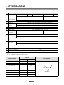
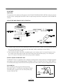
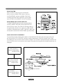
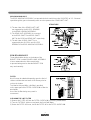
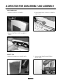
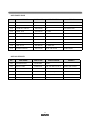
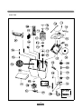
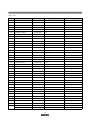
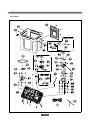
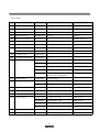
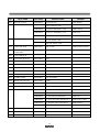
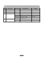
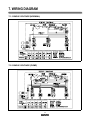
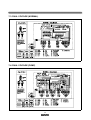
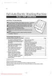
Service Manual
Washing Machine
Model: DWM-7510
DAEWOO ELECTRONICS CO., LTD.
TABLE OF CONTENTS
1. SPECIFICATIONS ................................................................................................................................. 1
2. EXTERNAL VIEW ................................................................................................................................. 2
3. PRINCIPLES OF OPERATION AND EXPLANATION OF FUNCTIONS ............................................. 3
4. DIRECTION FOR DISASSEMBLY AND ASSEMBLY ......................................................................... 7
5. TROUBLESHOOTING GUIDE ............................................................................................................. 10
6. EXPLODED VIEW AND PARTS LIST .................................................................................................. 15
7. WIRING DIAGRAM ................................................................................................................................ 23
1. SPECIFICATIONS
NO
1
2
ITEM
SPEC IFIC A TION S
POW ER
SOURCE
VOLTAGE
FREQUENCY
60Hz
50Hz
POW ER
CONSUM PTION
PUMP
640W
610W
NON PUMP
580W
550W
3
DIMENSION
4
MACHINE
W EIGHT
AC 110V
AC 1 20V
AC 220V
AC 127/220V
AC 110/220V
AC 220V
NET : 874 X 532 X 989, PACKED UP : 898 X 558 X 1015 (W XDXH)
PUM P
NET : 40kg, PACKED UP : 44kg
NON PUM P
NET : 38kg, PACKED UP : 42kg
5
WASHING COURSE
6
WATER LEVEL
7
REVOLUTION
PER M INUTE
WASH
100 rpm
100 rpm
SPIN
1700 rpm
1400 rpm
TIM ER
WASH
M AX. 15 min., Manual operation
SPIN
M AX. 5 min., Manual operation
8
9
WASHER TYPE
10
SPIN TYPE
11
MAXIMUM MASS
OF TEXTILE
STRON G, NORM AL
HIGH : 72
, M EDIUM : 61 , LOW : 52
PULSATOR TYPE
CENTRIFUGALLY SEPARATED TYPE
WASH
7.5kg
SPIN
7.0kg
12
WATER SUPPLY
13
SPIN RINSE
14
OUTLET OF DRAIN HOSE
15
LINT FILTER
MANUAL
O
REAR
O
N O TE : E xplanation table for suffix of nam es.
SUFFIX
POW ER SOU RCE
EXPLANATION
NO N PUM P
PU MP
AC 100V 50/60Hz
J
-
A C 110V 60H z
T
TP
A C 120V 60H z
A
AP
A C 220V 50H z
N
NP
A C 220V 60H z
L
LP
A C 240V 50H z
M
MP
A C 110/220V 50H z
D
DP
A C 127/220V 60H z
S
-
2
M odel N am e
DW M - XXXX N P
P ower S ource
Pum p
AC 240V
2. EXTERNAL VIEW
2-1. STRUCTURE OF THE WASH MACHINE
DRAIN STRAINER
FILTER AS
GUIDE FILTER
COVER SAFETY
PANEL B
DOOR SPIN
DRAIN HOSE
BASKET SPIN
PLATE T
DOOR WASH
PULSATOR
CABINET
2-2. CONTROL PANEL(PANEL B ASS'Y)
W AS H T IM E R
W A SH AC TIO N
VA LV E SE LE C TO R
IN LE T WAT ER
LE VE R W AT ER
SU PP LY SE LEC TO R
SP IN T IM E R
W ASH TIMER
U se to select the desired tim e for w ashing or rinsing.
W ASH ACTION
U se to select w ash action. (“S TR O N G ”, “N O R M A L”)
VALVE SELECTOR
S elect “W A S H .R IN S E ” for w ashing and rinsing, and “D R A IN ” to drain the w ater.
(In case P U M P M O D E L turn on the drain pum p.)
“O FF” to turn off the drain pum p. (O nly P U M P M O D E L)
LEVER WATER SUPPLY SELEC TOR
Left : w ater supply in the W A S H T U B
R ight: : w ater supply in the B A S K E T S P IN .
INLET WA TE R
C onnect inlet hose to supply w ater in the W A S H TU B or B A S K E T S P IN .
SPIN TIMER
U se to select the desired tim e for spinning.
3
3. PRINCIPLES OF OPERATION AND EXPLANATION OF FUNCTIONS
W A S H T IM ER
FUNCTION
T he m ain sw itch rem ains O N during the w ashing tim e set by turning the tim er knob.
A t the sam e tim e, the internal switch T1 and T2 w hich provide pow er to W A SH M O TO R alternately at assigned Intervals.
S elect sw itch knob sets the w ash type by m eans of controlling the interval of internal sw itch contact.
STRUCTURE AND PRINCIPLE O F ACTIVATION
CIRCUIT DIAGRAM
4
S P IN TIM E R
FUNCTION
The spin tim er is the sw itch providing pow er to the S P IN M O TO R (D R A IN P U M P M O TO R ) during the set spin
dry tim e, and is a spring-type tim e sw itch com es on upon turning and those contact points com es off after the
set tim e.
STRUCTURE AND PRINCIPLE OF ACTIVATION
1) T he m ain shaft turns due to the unw inding force w hen the spin tim er is turned, the spring w ound w ith that
force being delivered through each gear and the spring slow ly unw inding at a speed finally
controlled by the angle assem bly.
2) The contact point turns O N and the assem bly angle is set in m otion, w hich is in the C A M groove in the
O F F state, com es off the groove w hen the m ain shaft is turned to w ind the spring. The contact point
turns O FF, return to C A M groove w hen the spring unw ind com pletely.
SAFETY DEVICE FOR BASKET SPIN
T he B A S K ET S P IN is an apparatus w hich elim inates the w ater from the laundry through centrifugal separation
generated by rapid revolution(approxim ately 1,600rpm for 60H z). A ccordingly, there are a D O O R S W IT C H
to cut off the pow er going into the D O O R S P IN is opened and a brake system to stop the rotating B A S K E T S P IN .
DOOR SW ITCH
W hen the D O O R S P IN is opened during spinning,
the D O O R S W ITC H LE V E R w hich sites atop the D O O R
S P IN falls off the contact, and cuts off the pow er going
into the S P IN M O TO R .
5
BRAKE SYSTEM
W hen the D O O R S P IN is opened, LIN K W IR E
w hich connect to D O O R S P IN loosens. A nd then
the B R A K E B A N D touches the D R U M C O U P LIN G
assem bly and stops the S P IN D R Y E R as it is pulled
by the S P R IN G in the B R A K E F IX P LATE assem bly.
BRAKE BAND GAP CONTROL METHOD
The B A N D B R A K E w orks best w hen the gap betw een
it and the D R U M C O U P LIN G is about 2m m w hen the
D O O R S P IN is closed. T he S P IN D R Y E R stops slow ly if
the gap betw een the tw o is too narrow, the S P IN D R Y E R
revolution is affected and the P LATE C O N TR O L W IR E m ay
be adjusted to m aintain the B R A K E B A N D gap adequately.
BA SKET SPIN
PLATE
CO NTROL WIRE
W ASH DECELERATOR ASSEM BLY
The initial deceleration follow ing the activation of the W A S H M O TO R takes place through the P U LLE Y
M O TO R and P U LLE Y P U LS ATO R , and the secondary deceleration is done by the gear in the G E A R
H O U S IN G w hich also increases their revolution strength. This revolution speed and strength is delivered to
the P U LS ATO R , w hich is then able to cause w ater current that is strong yet soft so that w ash loads are not
dam aged.
M O TO R W A S H
A bout 1,700rpm (60H z)
1,400rpm (50H z)
P U LLE Y P U LS ATO R
A bout 330rpm (60H z)
330rpm (50H z)
WASH MOTOR
P U LS ATO R
A bout 100rpm (60H z)
100rpm (50H z)
6
GEAR HOUSING ASS'Y
The G E A R H O U S IN G A S S E M B LY is a transm ission device w hich turns the P U LS ATO R at 3.3 : 1 low ered
speed through the gear unit assem bly w hich receives pow er at the G E A R S H A FT U N IT.
STRUCTURE
1) The tw o sides of the G E A R S H A FT U N IT
are supported by the O ILLE S S B E A R IN G
in the G E A R H O U S IN G A S S E M B LY.
2) The G E A R U N IT A S S E M B LY is connected
to the G E A R S H A FT 1 and G E A R S H A FT
U N IT by the G E A R and G E A R U N IT respectively.
3) The tw o sides of G E A R S H A FT 1 are
supported by the O IL S E A L and O ILLE S S
B E A R IN G in the G E A R H O U S IN G A S S E M B LY.
SPIN BELLOW S ASS'Y
The w rinkled rubber device on the bottom of the
B A S K E T S P IN is called S P IN B E LLO W S A S S E M B LY.
It has a w aterseal and a oilless m etal inside
to prevent leakage and so that the B A S K E T S P IN
m ay w ork sm oothly.
FILTER
M uch lint m ay be obtained depending upon the kind of
clothes to be w ashed and sam e of the lint m ay also be
suck to the clothes.
To m inim ize this possibility, a lint filter is provided
on the upper part of the F ILTE R O V E R FLO W to filter the
w ash w ater.
U se of the lint filter during every w ash is
recom m end.
CLEANING THE LINT FILTER
1) R em ove the FILTE R A S from the FILT E R O V E R FLO W by pressing it dow nw ards.
2) Turn the FILT E R A S inside out, and w ash the lint off w ith w ater.
3) R eturn the FILTE R A S it w as, and fix the F ILTE R A S to the FILTE R O V E R FLO W.
7
4. DIRECTION FOR DISASSEMBLY AND ASSEMBLY
ASSY PANEL BACK
1. R em ove 5 screw s on the PA N E L B .
2. R em ove K N O B and 2 screw s on the PA N E L B .
(S pin Tim er)
3. R em ove C O N TR O L LE V E R and W A S H
T IM E R .
BASKET SPIN
4. R em ove 5 screw s on the C O V E R B A C K .
5. R em ove LIN K B R A K E and A S S E M B LY
B R A K E W IR E .
8
6. R em ove 1 bolt and nut on the upper side of the
D R U M C O U P LIN G A S .
7. R em ove 2 screw s on the P LATE T.
8. Lift up the B A S K E T S P IN .
ASSY BASE UNDER
9. R em ove 1 screw on the C A B IN E T.
10. S eparate H A R N E S S A S connectors.
11. R em ove a V -B E LT from P U LLE Y M O TO R .
9
12. Turn over the w ashing m achine.
13. R em ove 7 screw s on the B A S E U N D E R
A S S Y.
14. R em ove 3 screw s on the B R A C K E T S P IN ,
and rem ove the S P IN M O TO R .
15. R em ove 3 bolts on the B A S E U N D E R ,
and rem ove the W A S H M O TO R .
16. R em ove 3 screw s on the C O V E R P U M P.
(In case of P U M P M O D E L)
10
5. TROUBLESHOOTING GUIDE
N ote : P ull out the pow er plug to repair and m ake sure that the W ashing M achine has been properly grounded.
Concerning W ash
Problem
Cause
Check Point
Is the Power properly connected?
Pulsator does
not rotate.
Solution
NO
Reconnect the Power Cord.
YES
NO
Is there a whirring sound from the
W ash Motor when turned on?
Is the fuse blown?
YES
Change the fuse.
YES
Is the Condenser properly
connected?
NO
Motor does not start due
to opening the Condenser
circuit.
Reconnect the Condenser.
NO
Is the M otor hot?
(In the case there is Thermal Protector)
YES
Power has been cut off
by the Thermal Protector.
W ash restart when
Motor cools.
NO
NO
Improper wiring.
Reconnect the wiring.
Defective W ash Timer.
Replace W ash Tim er.
Defective Wash Motor.
Replace Wash M otor.
The wash load is more
than 7.5kg.
Reload with proper wash
load.
Defect of mechanical
assembly.
Tighten the screws fixed
on the Pulley.
W orn out V-Belt.
Replace V-Belt.
YES
Revolution obstructed by
im purities.
Rem ove impurities after
disassem bling pulsator.
YES
Worn out the serration
within the pulsator.
Replace pulsator.
Is the W iring good?
(Refer to the W iring Diagram)
YES
Is the contact of W ash Timer good?
NO
YES
Is the wash load appropriate?
Pulsator does not
rotate smoothly.
NO
YES
Are the Pulsator and Motor Pulley
securely assem bled?
NO
YES
YES
Does the V-Belt slip?
NO
Are there imputities between the
Pulsator.
NO
Does the Gear Housing As Shaft rotate
propely when the pulsator has been
disassembled?
NO
Defective Gear Housing As.
11
Replace Gear Housing As.
Problem
Check Point
Cause
NO
Is the wiring of Wash Condenser
properly connected?
Pulsator only
rotates in one
direction.
Solution
Improper wiring.
Reconnect.
Improper wiring.
Reconnect the Wash
Timer.
Defective W ash timer.
Replace W ash Timer.
YES
Is the wiring of Wash Timer properly
connected?
NO
YES
Are there strange noise from Tub when
the Pulsator rotate?
There is excessive
noise during
washing.
YES
Im purtities between
Pulsator and Tub.
YES
Rem ove im purities after
disassem ble Pulsator.
NO
Pulsator im properly
assem bled.
NO
Tighten the Pulsator
fixing screw.
Something is in contact
with the Pulsator Pulley or
Motor Pulley or other
rotating parts.
Adjust the parts so that
there are no im purities in
contact with rotating parts.
Cause
Solution
Concerning Spin
Problem
Check Point
YES
Is the D oor Spin open?
The Basket Spin
does not rotate.
The contact of Door
Switch is open.
Keep the Door Spin
closed during spin.
NO
YES
Is the Fuse blown?
Change the Fuse.
NO
Is there a w hirring sound from the
Spin M otor w hen turned ON ?
NO
YES
Is the C ondenser properly connected?
NO
YES
12
Motor does not start due
to opening the C ondenser
circuit.
Reconnect the Condenser.
Problem
Cause
Check Point
Solution
YES
YES
Brake W ire is too long.
The Brake Band is touching
the Drum Coupling Assembly.
The Basket Spin
does not rotate.
NO
Brake Spring is broken.
Assem ble after loosening
Link Brake.
R eplace Brake Spring.
NO
Is the Motor hot?
(In the case there is Therm al Protector)
YES
Power has been cut off
by the Thermal Protector.
Spin restart when
M otor cools.
Im proper wiring.
Reconnect the W iring.
NO
NO
Is the W iring good?
(R efer to the W iring Diagram )
YES
Is the Door Sw itch Lever properly
placed on the Door Spin?
NO
Defective connection.
Replace Door Switch or
Reconnect the Door Switch.
YES
Is the Door Switch term inal properly
connected?
YES
Improper w iring.
Reconnect the term inal.
YES
NO
Is the contact of Spin Tim er good?
D efective Spin Tim er.
Replace the Spin Tim er.
D efective Spin M otor.
Replace the Spin Motor.
Basket Spin does not
balanced due to wash load.
R eload the clothes so they
are well balanced.
Basket Spin does not
balanced due to w ash load.
Reload the colthes and
press down the Safety
Cover into Basket Spin .
Im proper assem bly.
Tighten the Bolt in D rum
Coupling Assem bly.
YES
NO
Is the w ash load w ell balanced?
There are strange
noise and severe
vibration during
spinning.
YES
Are clothes or the Safety Cover
stick out from Basket Spin ?
NO
YES
YES
Is the assembly betw een the Drum
Coupling Assem bly and Spin M otor
or Basket Spin loose?
NO
NO
Basket Spin unbalance.
Is The Basket Spin itself w ell Balanced?
YES
13
R eplace Basket Spin.
Check Point
Problem
Cause
Solution
YES
The W aterseal or the Oilless m etal in the
Bellows Assem bly worn out.
There are strange
noise and severe
vibration during
spinning.
There is leakage
during spinning.
NO
Is the Bellows Assembly properly
assembled?
W aterproofing not working
due to defective assem bly.
Replace Bellows Assem bly.
Re-assem ble Bellows
Assem bly.
YES
The W aterseal or the Oilless
Metal in the Bellows Assembly
is worn out.
Basket Spin does
not stop with the
Door Spin open.
NO
The Brake Band touches the Drum
Couping when the Door Spin open.
Brake wire is too short.
Assemble after losening
Link Brake.
Brake Bnad is worn out.
Replace Brake Band or
Brake Fix Assembly.
Defecive Door Switch.
Replace Door Switch.
The contact of the Door
Switch does not open due
to deformity of the Lever
of Door Switch.
Replace Door Switch or
Reconnect the Door Switch.
Cause
Solution
The Drain Hose is too high.
Hang the Drain Hose lower.
YES
Impurities are obstructing
drainage.
Disassemble Pulsator and
take out impurities in Drain
strainer.
YES
Impurities are obstructing
drainage.
Remove impurities or
replace Valve Housing or
Inlet Joint.
Impurities are blocking the
Drain Hose.
Remove impurities.
YES
NO
Is the electric connection of the Door
Switch good?
Replace Bellows Assem bly.
YES
Concerning Drainage (Pum p)
Problem
Drainage is not
satisfactory.
Check Point
Is the height of the drainage area where
the Drain Hose hangs over 1m?
YES
NO
Are there impurities in the Drain Strainer?
NO
Are there impurities in the
Valve Housing or Inlet Joint?
NO
14
Problem
Draining does not
function during
drain selecting.
Check Point
Is the Drain Selector in the DRAIN
position?
Cause
NO
The position is fault.
Solution
Turn the Drain Selector
to DRAIN.
YES
NO
Is the pump Motor wiring properly
connected?
Defective wiring.
Reconnect wiring.
Defective Pump Motor.
Replace Pump Motor.
Defective wiring.
Reconnect wiring.
Defective Spin Timer.
Replace Spin Timer.
Defective Pump Motor.
Replace Pump Motor.
YES
Draining does not
function during
Spinning.
Are the wiring of the Spin Timer and
the Pump Motor good?
NO
YES
NO
Is the Spin Timer contact good?
YES
Concerning Drainage (NON PUM P)
Problem
Check Point
Cause
YES
Drainage is not
satisfactory.
Are there impurties in the Drain Strainer?
Impurities are obstrusting
drainage.
Disassemble Pulsator and
take out impurities in Drain
Strainer.
Impurities are obstrusting
drainage.
Remove impurities or replace
Valve Housing or Inlet Joint.
NO
Are there impurities in the Valve Housing
or Inlet Joint?
YES
NO
Water Keeps
Draining during
wash.
Is the Drain Selector DRAIN position
on the panel.
YES
NO
15
Solution
Impurities are blocking the
Drain Hose.
Remove impurities.
The position is fault.
Turn the Drain Selector to
WASH/RINSE position.
There are impurities
between Valve Housing
and Valve Bellows.
Remove impurities or
replace Valve Housing.
6. EXPLODED VIEW AND PARTS LIST
ASSY PANEL BACK
16
ASSY PANEL BACK
NO.
PART NAM E
PART CODE
SPECIFICATION
REM ARK
P01
KNO B
3613402400
HIPS
CO LO R O PTIO N
P02
PANEL B
3614220900
HIPS
CO LO R/LETTER O PTIO N
P03
LEVER W.S SELECT
3613701000
PP
CO LO R O PTIO N
P04
TIM ER SPIN
3619910100
S-7510A
P05
TIM ER WASH
3619910200
S-K75A
P06
SW ITCH DRAIN
3619043700
VP531A -2H, 250VAC/15A
P07
LEVER CO NTRO L
3613700800
PO M
P08
BRACKET C O NTRO L
3610604200
HIPS
P09
LINK VALVE
3617801500
PP BAND W 6
P10
HARNESS DRAIN
3612757500
7510P SW DRAIN
PUM P M O DEL
ASSY ACCESSORY
NO.
PART NAM E
PART CODE
SPECIFICATION
REMARK
A01
CO VER SAFETY
3611416300
PELD
A02
HO SE CLAM P
4508A06120
SW 2.6D ZN8-C (R15.5)
NO N PUM P M O DEL
A03
DRAIN HO SE
3613223000
L=1100m m
NO N PUM P M O DEL
A04
CLAM P HO SE O
3611202400
HSW -3, 4.0 kg
PUM P M O DEL
A05
HO SE DRAIN O
3613222600
4010P, O SUNG SA
PUM P M O DEL
A06
G UIDE DRAIN H O SE
3612502300
PP
PUM P M O DEL
17
ASSY TUB
PUMP MODEL
18
ASS Y TUB
NO
PART NAM E
PART CODE
SPECIFICATION
REMARK
T 01
TUB
3618815600
PP
T 02
DOOR WASH
3611795000
H IP S
C O LO R O PT IO N
T 03
P U LS AT O R A S
3619704700
7.5kg
C O LO R O PT IO N
T 04
S P EC IA L SC R E W
3616002900
S U S 304
T 05
G U ID E D O O R
3612507100
PP
T 06
D R AIN S T RA IN ER
3619606600
PP
T 07
B A SE W ATE R S UP P LY
3610387100
PP
T 08
F ILT E R A S
3611904000
P P + PO LY E S T ER
T 09
F ILT E R O V E RF LO W
3611903700
PP
T 10
C O VE R B AS K E T
3611416000
PP
T11
B O LT SP IN BA S K E T
4506B19031
T 12
P LAT E U P P ER
3614516900
S P G T1.2
T 13
B A SK E T S PIN
3619102400
SPCE
T 14
P LAT E U N D ER
3614517900
S P G T2..0
T 15
F IX TU R E SH A FT A S
3612005300
7.0kg
T 16
B E LLO W S A S
3616401600
7.5kg
T 17
F IX TU R E BE LLO W S
3612005100
PP
T 18
LIN K B R A KE
3617801600
P P B AN D W 6
T 19
S P RIN G CO V E R
3615109100
SW C
T 20
W IND O W S P IN
3615501900
ABS
C O LO R O PT IO N
T 21
D O O R S P IN
3611794900
H IP S
C O LO R O PT IO N
T 22
S W IT C H CO V E R
3619001200
15A 220VA C RW -622,250
T 23
P LAT E T
3614517000
PP
T 24
C O VE R INN E R
3611416100
PP
T 25
PA C K IN G
3614001900
NBR
T 26
G E AR H O US IN G A S
3617306200
D W M -7510S R =3.3:1
T 27
P U LLE Y P ULS ATO R
3618405500
FRPP
T 28
S P EC IA L BO LT
3616008400
M 6 S IDE F IXIN G
T 29
PA C K IN G
4509A05032
NR
T 30
VA LV E C AP
4505F06013
PP
T 31
S P RIN G VA LV E
4505C06020
S U S 304 W R D 1.0
T 32
R O D VA LV E
3618504000
PP
T 33
B E LLO W S VALVE
4505C06040
NR
T 34
IN LET JO INT
3617503800
PP
T 35
C A SE VA LV E
3611118200
PP
T 36
CAP
3610909800
PP
T 37
H O SE O V ER F LO W
4506H60610
P E -H D
T 38
E LBO W D RA IN
3617101900
PP
N O N PU M P M O D EL
H O SE A
3613217420
P E -LD/E VA , O -SU N G
P U M P M O D EL
19
C O LO R O PT IO N
D14
C O LO R O PT IO N
P U M P M O D EL
ASSY MAIN
20
A S S Y M A IN
NO
PART NAM E
PART CODE
SPECIFICATION
REM ARK
M 01
CAB INET W ELD AS
PRAW PS0000
7510S
C O LO R O PTIO N
M 02
HAN DLE CABINET
4506J03010
PE-HD
C O LO R O PTIO N
M 03
CO VER BACK
3611416200
T0.4x520x610
M 04
TERM INAL BLO CK
3618701900
271-312
O PTIO N
M 05
BRA CKET TERM INAL
4505D37002
PP
O PTIO N, T/BLO CK
M 06
HAR NESS PO W ER
3612756810
7510M P, T/BLO C K 250-CO N .
O PTIO N, T/BLO CK
M 07
HAR NESS
4505D64081
16/0.26X340 FO R G ND .
O PTIO N, T/BLO CK
M 08
BASE UNDER
3610387000
PP
N O N PUM P M O DEL
BASE UNDER
3610387010
PP, PUM P
PU M P M O DEL
M 09
CU SHIO N SPO T
450M 712010
PP
M 10
CU SHIO N W /M M O TO R
3611506200
NR
M 11
M O TO R WASH
3618949700
AC 110V 60Hz, W 1D42ED001
D W M -7510T(P)
3618950800
AC 120V 60H z, W 1D42JD001
D W M -7510A(P)
3618949300
AC 220V 60H z, W 1D42UD 101
D W M -7510, L
3618949500
AC 220V~240V 50Hz, W 1D42VD101
D W M -7510N(P), M (P)
3618949900
AC 110V/220V 50Hz,
120/240V 60Hz, W 1D42G D001
D W M -7510S,D(P)
M 12
SPEC IAL BO LT
3616003100
M 5x35 WASHER
M 13
PULLEY M O TO R
4506H 12011
ADC-12
60Hz
4509A20022
ADC-10
50Hz
M 14
BO LT HEX
7342602011
6B-2 6x20 PO INTING M FZN
M 15
NU T HEX
7393600011
6N-3-6 M FZN
M 16
BELT V
450M 700020
M -32
M 17
DRAIN PUM P
3619601610
AC 110V 60Hz CO N.
D W M -7510TP
3619610030
AC 120V 620Hz CO N.
D W M -7510AP
3619600720
AC 220~240V 50Hz CO N.
D W M -7510NP,M P
3619603810
AC 110/220V 50Hz CO N .
D W M -7510DP
M 18
RING E
7402003031
ER-3 SKZN
PU M P M O DEL
M 19
FAN CO O LING
3611801300
ABS
PU M P M O DEL
21
NO
PART NAM E
PART CODE
SPECIFICATION
REMARK
M 20
BR ACKET PUM P
3610604000
PP(O SU NG SA)
PUM P M O DEL
M 21
UNIT CO NDEN SER
3618943020
50/25
DW M -7510T(P)
3618950600
41.6/20.8uF 200/230VAC CO N.
DW M -7510A(P)
3618943420
12.5/5.2
DW M -7510L
3618948300
M 22
CAPACITO R WASH
4505E11000
4509C11020
200VAC CO N.
400/440VAC CO N.
10.4/5.2 400/440VAC CO N.
25 x2 200VAC CO N.
20.8 x2 200VAC CO N.
20.8 CO N .
DW M -7510N(P), M (P)
DW M -7510D(P),DU AL
DW M -7510S,DUA L
DW M -7510D(P),S,DUAL
M 23
CAPACITO R SPIN
4509C11010
M 24
HARNESS
CO NDEN SER
3612706710
M 25
CO RD PO W ER AS
M 26
CO UPLING DRUM AS
4507K16001
7.5kg
M 27
NU T HEX
7393800011
6N-3-8 M FZN
M 28
BO LT HEX
7342802011
6B-2 8x20 PO INTING M FZN
M 29
NU T HEX
7393600011
6N-3-6 M FZN
M 30
BO LT HEX
7642602011
6B-2 6x20 PO INTING M FZN
M 31
BO LT HEX
7341500811
6B-1-5x8 M FZN
M 32
SPR ING BRAKE
4507K53010
SW C D1.0 ZNB-C
M 33
BR AKE FIX PLATE AS
4505C54000
2-WAY
M 34
ASSY BRAKE W IRE
3619201800
SUS W IRE + PP
M 35
BO LT HEX
7341501611
6B-1-5x16 HS M FZN
M 36
M O TO R SPIN
3618949600
AC 110V 60Hz W 1D35 EF001
DW M -7510T(P)
3618950700
AC 120V 60Hz W ID35JF001
DW M -7510A(P)
3618949200
AC 220V 60Hz W 1D35UF001
DW M -7510, L
3618949400
AC 220V~240V 50Hz W 1D35VF001
DW M -7510N(P), M (P)
3618950100
AC 110/220V 50Hz W 1D35FF002
DW M -7510D(P)
3618950000
AC 120/240V 60Hz W 1D35LF002
DW M -7510S
CO NNECTO R A, B
-
DUAL VO LTAG E
-
M 37
CU SHIO N M O TO R SPIN
3611532900
PP
M 38
BRACKE T M O TO R SPIN
3610604100
SPG T1.4
M 39
STO PPER
4506H14020
PEHD
22
NO
PART NAM E
PART CODE
M 40
SPR ING CUSHIO N
4507K14010
SW C D3.2
M 41
RU BBER DAM PING
4506H14030
NBR
M 42
STO PPER LO W ER
3615200800
PP
M 43
HA RNESS AS
3612756300
7.5kg DUAL, NO RM AL
3612756400
7.5kg DUAL, PUM P
3612756500
7.5kg SING LE, N O RM AL
3612756600
7.5kg SING LE, P UM P
3612757800
UL1015 AW G 18 L=490 + 600
PUM P M O DEL
3612757810
UL1015 AW G 18, L=490
NO N PUM P
M 44
HA RNESS EARTH
SPECIFICATION
23
REMARK
NO N PUM P
NO N PUM P
7. WIRING DIAGRAM
7-1. SINGLE VOLTAGE (NORMAL)
7-2. SINGLE VOLTAGE (PUMP)
24
7-3. DUAL VOLTAGE (NORMAL)
7-4. DUAL VOLTAGE (PUMP)
25
DAEWOO ELECTRONICS CO., LTD
686, AHYEON-DONG MAPO-GU
SEOUL, KOREA
C.P.O. BOX 8003 SEOUL, KOREA
TELEX : DWELEC K28177-8
CABLE : “DAEWOOELEC”
E-mail : [email protected]
FAX : 02) 360-8184
TEL: 02) 360-8178~8181
S/M NO. : DW75100001
PRINTED DATE : JUL. 1998