1
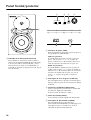
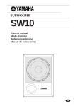
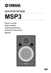
MONITOR SPEAKER
MSP10
MSP10M
Owner’s manual
Mode d’emploi
Bedienungsanleitung
Manual de instrucciones
M
Thank you for purchasing the Yamaha MSP10/10M monitor speaker system. The
MSP10/10M features a compact bass reflex cabinet, with a 20 cm two-way cone
speaker and a 2.5 cm titanium dome speaker. This powered bi-amplifier speaker
system faithfully reproduces sound and can be used for a wide range of applications,
from personal home recordings to serious professional use. Please read this Owner’s
Manual thoroughly to make the best use of the MSP10/10M’s quality functions for the
longest period of time, and keep the manual in a safe place.
Precautions
Warnings
Cautions
• Do not allow water to enter this unit or allow the
unit to become wet. Fire or electrical shock may
result.
• Connect this unit’s power cord only to an AC outlet
of the type stated in this Owner’s Manual or as
marked on the unit. Failure to do so is a fire and
electrical shock hazard.
• Do not scratch, bend, twist, pull, or heat the power
cord. A damaged power cord is a fire and electrical
shock hazard.
• Do not place heavy objects, including this unit, on
top of the power cord. A damaged power cord is a
fire and electrical shock hazard. In particular, be
careful not to place heavy objects on a power cord
covered by a carpet.
• If you notice any abnormality, such as smoke, odor,
or noise, or if a foreign object or liquid gets inside
the unit, turn it off immediately. Remove the power
cord from the AC outlet. Consult your dealer for
repair. Using the unit in this condition is a fire and
electrical shock hazard.
• Should this unit be dropped or the cabinet be
damaged, turn the power switch off, remove the
power plug from the AC outlet, and contact your
dealer. If you continue using the unit without
heeding this instruction, fire or electrical shock may
result.
• If the power cord is damaged (i.e., cut or a bare
wire is exposed), ask your dealer for a replacement.
Using the unit with a damaged power cord is a fire
and electrical shock hazard.
• Do not remove the unit’s cover. You could receive
an electrical shock. If you think internal inspection,
maintenance, or repair is necessary, contact your
dealer.
• Do not modify the unit. Doing so is a fire and
electrical shock hazard.
• When rack-mounting the unit, allow enough free
space around the unit for normal ventilation. This
should be: 10 cm at the sides, 30 cm behind, and
60 cm above.
For normal ventilation during use, remove the rear
of the rack or open a ventilation hole.
If the airflow is not adequate, the unit will heat up
inside and may cause a fire.
• This unit has ventilation holes at the rear to prevent
the internal temperature rising too high. Do not
block this. Blocked ventilation holes are a fire
hazard.
• This unit is heavy. Use two or more people to carry
it.
• Keep this unit away from the following locations:
— Locations exposed to oil splashes or steam, such
as near cooking stoves, humidifiers, etc.
— Unstable surfaces, such as a wobbly table or
slope.
— Locations exposed to excessive heat, such as
inside a car with all the windows closed, or
places that receive direct sunlight.
— Locations subject to excessive humidity or dust
accumulation.
• Hold the power cord plug when disconnecting it
from an AC outlet. Never pull the cord. A damaged
power cord is a potential fire and electrical shock
hazard.
• Do not touch the power plug with wet hands.
Doing so is a potential electrical shock hazard.
3
Operating Notes
• Turn off all musical instruments, audio equipment,
and speakers when connecting to this unit. Use the
correct connecting cables and connect as specified.
• Always lower the volume control to minimum
before turning on the power to this unit. A sudden
blast of sound may damage your hearing.
• Do not raise the volume of headphones or speakers
to a level that makes you feel uncomfortable.
Listening to loud music for long periods can
damage your hearing.
• This speaker is magnetic shielded. However, if a
nearby monitor displays any uneven colors, place it
further away from the monitor.
• You may feel a flow of air in and out of the port on
this unit. This is not abnormal and sometimes
occurs when a program with a lot of bass range is
played.
• XLR-type connectors are wired as follows: pin 1:
ground, pin 2: hot (+), and pin 3: cold (–).
WARNING: THIS APPARATUS MUST BE EARTHED
IMPORTANT
THE WIRES IN THIS MAINS LEAD ARE COLOURED IN
ACCORDANCE WITH THE FOLLOWING CODE:
GREEN-AND-YELLOW :
EARTH
BLUE :
NEUTRAL
BROWN :
LIVE
As the colours of the wires in the mains lead of this apparatus may
not correspond with the coloured markings identifying the terminals in
your plug, proceed as follows:
The wire which is coloured GREEN and YELLOW must be
connected to the terminal in the plug which is marked by the letter E
or by the safety earth symbol
or coloured GREEN and YELLOW.
The wire which is coloured BLUE must be connected to the terminal
which is marked with the letter N or coloured BLACK.
The wire which is coloured BROWN must be connected to the
terminal which is marked with the letter L or coloured RED.
* This applies only to products distributed by YAMAHA KEMBLE
MUSIC (U.K.) LTD.
4
Front panel/Rear panel
2
3
4
5
+4dB
MIN
–2 –1 0
LOW
–1 0 +1
HIGH
TRIM
ON OFF
(80Hz)
LOW CUT
–6dB
SENSITIVITY
INPUT
1
ON
OFF
POWER
6
2 TRIM switches
These switches enable you to adjust the bass and
treble for the MSP10/10M.
1 Power/Clip indicator
This indicator lights up green when you turn the
POWER switch on the rear panel ON. If the output
level is too high, causing clipping at the amplifier,
the indicator lights up red. In this case, lower the
input level.
LOW: three positions
The LOW switch adjusts the bass range. With the
“–1” and “–2” settings, the bass range is cut by
1.5 dB when based on a reference value of 50 Hz
with the “0” setting.
HIGH: three positions
The HIGH switch adjusts the treble. With the “+1”
setting, the treble range is boosted by 1.5 dB when
based on a reference value of 10 kHz with the “0”
setting. With “–1” setting, the treble range is cut by
1.5 dB.
3 LOW CUT switch
This switch turns on or off the high-pass filter that
cuts frequency ranges below 80 Hz.
4 SENSITIVITY control
Adjust the volume according to the output
sensitivity of the connected device.
(The factory default setting is “MIN.”)
5 INPUT jack
This is an XLR-type balanced input jack.
6 POWER switch
This switch turns the power to the MSP10/10M on
and off. When you turn this switch on, the power/
clip indicator lights up green.
5
Specifications
General specifications
Type........................................... Amplified 2Way Bass Reflex Powered Speaker (Bi-Amp.)
Crossover Frequency .................. 2.0 kHz, 30 dB/oct
Frequency Range ....................... 40 Hz to 40 kHz (–10 dB)
Sensitivity .................................. –10 dB at –6 dB position (for 100 dB/SPL, 1 m on Axis)
Maximum Output Level ............. 110 dB (1 m on Axis)
Dimensiones (W × H × D).......... 265 × 420 × 329 mm
Weight ....................................... 20 kg
Speaker unit
Speaker Unit .............................. LF: 20 cm Cone (4Ω, magnetic shielded)
HF: 2.5 cm Titan Dome (8Ω, magnetic shielded)
Enclosure ................................... Type: Bass Reflex
Amp.unit
Maximum Output Power............ LF: 120 W at 400 Hz, THD= 0.02%, RL= 4Ω
HF: 60 W at 10 kHz, THD= 0.02%, RL= 8Ω
Input Sensitivity/Impedance ....... –6 dB to +4 dB/10 kΩ
Hum & Noise............................. ≤–67 dBu (Volume= Min) DIN Audio filter
Signal to Noise Ratio.................. ≥98 dB (IEC-A Weighting)
Controls ..................................... TRIM Switch
LOW: 3 positions (0 dB, –1.5 dB, –3 dB at 50 Hz)
HIGH: 3 positions (+1.5 dB, 0 dB, –1.5 dB at 10 kHz)
LOW CUT Switch: ON/OFF
SENSITIVITY Control
POWER Switch: ON/OFF
Connectors ............................... Input XLR-3-31
Power Indicator/Clip Indicator ... Green/Red LED
Power Requirement.................... USA and Canada: AC 120 V, 60 Hz
Europe:
AC 230 V, 50 Hz
Others:
AC 240 V, 50 Hz
Power Consumption................... 150 W
Option ....................................... Wall mounting bracket BWS251-300
Specifications and appearance are subject to change without notice.
For European Model
Purchaser/User Information specified in EN55103-1 and EN55103-2.
Inrush Current: 11A
Conformed Environment: E1, E2, E3 and E4
Dimensions
Performance graph
Standard frequency response
RESPONSE (dB)
H: 420
+10
0
–10
–20
–30
85
120
W: 265
2-M8 Screws
5.5
262
D: 329
61.5
–40
20
100
1k
FREQUENCY (Hz)
Unit: mm
6
10k
Block Diagram
HPF
INPUT
EQ
HPF
SENSITIVITY
LOW CUT
0
–1
+1
LPF
0
–2
–1
LOW
HIGH
TRIM
Mounting the MSP10/10M on the wall
You can install the MSP10/10M on the wall using an optional Yamaha wall bracket BWS251-300. For more
information on how to install it, refer to the instructions that come with the wall bracket. For the angle and
position of installation, refer to the figure below.
The wall should be strong enough to support the speaker and equivalent to a sheet of plywood with a
thickness of 18 mm (11/16 inches) or more. Use appropriate tools for installation.
• Recommend for new constructions.
• Ask an installation specialist for instruction.
• Some installation parts may deteriorate due to friction or corrosion over a long period of time. For safety,
check these parts and condition regularly.
7
MSP10/10M
Mode d’emploi
Nous vous remercions d’avoir opté pour le système d’enceinte d’écoute MSP10/10M
de Yamaha. Le système MSP10/10M dispose d’un coffret bass reflex compact avec un
haut-parleur deux voies en cône de 20 cm et un haut-parleur avec un dôme en titane
de 2,5 cm. Ce système d’enceinte active biamplifiée reproduit le son avec fidélité et
peut avoir de nombreuses applications allant de l’enregistrement à domicile à un
usage professionnel intensif. Veuillez lire attentivement ce Mode d’emploi afin de
tirer le meilleur parti des qualités du MSP10/10M durant de longues années.
Conservez ensuite ce mode d’emploi dans un endroit sûr.
Précautions
Avertissements
• Evitez de mouiller l’appareil. Il y a risque
d’incendie ou d’électrocution.
• Ne branchez le cordon d’alimentation de cet
appareil qu’à une prise secteur qui répond aux
caractéristiques données dans ce manuel ou sur
l’appareil, faute de quoi, il y a risque d’incendie.
• Evitez de griffer, tordre, plier, tirer ou chauffer le
cordon d’alimentation. Un cordon d’alimentation
endommagé constitue un risque d’incendie ou
d’électrocution.
• Ne posez pas d’objets pesants (à commencer par
l’appareil lui-même) sur le cordon d’alimentation.
Un cordon d’alimentation endommagé peut
provoquer un incendie ou une électrocution. Cette
précaution est notamment valable lorsque le
cordon d’alimentation passe sous un tapis.
• Si vous remarquez un phénomène anormal tel que
de la fumée, une odeur bizarre ou un
bourdonnement ou, encore, si vous avez renversé
du liquide ou des petits objets à l’intérieur, mettez
l’appareil immédiatement hors tension et
débranchez le cordon d’alimentation. Consultez
votre revendeur pour faire examiner l’appareil.
L’utilisation de l’appareil dans ces conditions
constitue un risque d’incendie ou d’électrocution.
8
• Lorsque l’appareil tombe ou si le boîtier est
endommagé, coupez l’alimentation, débranchez le
cordon de la prise secteur et contactez votre
revendeur. L’utilisation de l’appareil dans ces
conditions constitue un risque d’incendie ou
d’électrocution.
• Si le cordon d’alimentation est endommagé (s’il est
coupé ou si un fil est à nu), veuillez en demander
un nouveau à votre revendeur. L’utilisation de
l’appareil avec un cordon d’alimentation
endommagé constitue un risque d’incendie ou
d’électrocution.
• N’ouvrez jamais le boîtier de cet appareil. Il y a
risque d’électrocution. Si vous pensez que
l’appareil doit subir une révision, un entretien ou
une réparation, veuillez contacter votre revendeur.
• Cet appareil ne peut pas être modifié par
l’utilisateur. Il y a risque d’incendie ou
d’électrocution.
Notes pour la manipulation
• Lors d’un montage en rack, laissez un espace libre
autour de l’appareil pour une bonne aération. Cet
espace doit être de 10 cm sur les côtés, 30 cm
derrière et de 60 cm sur le dessus.
Pour garantir une bonne aération durant
l’utilisation, ouvrez l’arrière du rack ou les orifices
de ventilation.
Si la circulation d’air est insuffisante, il y a
accumulation de chaleur ce qui peut provoquer un
incendie.
• Cet appareil est pourvu d’orifices d’aération à
l’avant afin d’éviter que la température interne ne
monte trop. Des orifices d’aération obstrués
constituent un risque d’incendie.
• Cet appareil est particulièrement lourd. Il doit être
porté par deux personnes au moins.
• Evitez de placer l’appareil dans les endroits
suivants:
— Les endroits soumis à des éclaboussures d’huile
ou à de la vapeur (à proximité de cuisinières,
d’humidificateurs, etc.).
— Des surfaces instables, telles un table mal
balancée ou une surface inclinée.
— Les endroits soumis à une chaleur excessive (à
l’intérieur d’un véhicule toutes fenêtres fermées)
ou en plein soleil.
— Les endroits particulièrement humides ou
poussiéreux.
• Débranchez toujours le cordon d’alimentation en
tirant sur la prise et non sur le câble. Un cordon
d’alimentation endommagé constitue un risque
d’incendie ou d’électrocution.
• Ne touchez pas la prise d’alimentation avec des
mains mouillées. Il y a risque d’électrocution.
• Coupez tous les instruments de musique, les
appareils audio et les enceintes avant de les
brancher à cet appareil. Utilisez les câbles de
connexion adéquats et branchez-les selon les
consignes données.
• Réglez le volume en position minimum avant de
mettre cet appareil sous tension. Une explosion
sonore brutale risque d’endommager votre ouïe.
• Ne choisissez jamais un niveau inconfortable pour
le volume du casque ou des enceintes. L’écoute de
musique à un volume élevé durant de longues
périodes peut endommager votre ouïe.
• Cette enceinte dispose d’un blindage magnétique.
Toutefois, si un écran placé à proximité affiche des
couleurs inégales, éloignez l’enceinte.
• Vous pouvez sentir un flux d’air entrant et sortant de
l’appareil. Ce n’est pas anormal et peut se produire
lors d’une reproduction avec beaucoup de grave.
• Le câblage des connexions XLR est le suivant:
broche 1= masse, broche 2= chaud (+), broche 3=
froid (–).
9
Français
Précautions
Face avant/Face arrière
2
3
4
5
+4dB
MIN
–2 –1 0
LOW
–1 0 +1
HIGH
TRIM
ON OFF
(80Hz)
LOW CUT
–6dB
SENSITIVITY
INPUT
1
ON
OFF
POWER
6
2 Commutateurs TRIM
Ces commutateurs vous permettent de régler le
grave et l’aigu pour le MSP10/10M.
1 Témoin de mise sous tension/saturation
Ce témoin s’allume en vert lorsque vous réglez le
commutateur POWER en face arrière sur ON (sous
tension). Si le niveau de sortie est trop élevé et
sature au niveau de l’amplificateur, ce témoin
s’allume en rouge. Dans ce cas, diminuez le
niveau d’entrée.
LOW: trois positions
Le commutateur LOW détermine la plage du grave.
Avec les réglages “–1” et “–2”, cette plage est
atténuée de 1,5 dB sur base d’une valeur de
référence de 50 Hz avec un réglage “0”.
HIGH: trois positions
Le commutateur HIGH détermine l’aigu. Avec un
réglage “+1”, la plage de l’aigu est accentuée de
1,5 dB sur base d’une valeur de référence de
10 kHz avec un réglage “0”. Avec un réglage “–1”,
la plage de l’aigu est atténuée de 1,5 dB.
3 Commutateur LOW CUT
Ce commutateur active ou coupe le filtre passehaut qui coupe les fréquences inférieures à 80 Hz.
4 Commande SENSITIVITY
Réglez le volume en fonction de la sensibilité de
sortie de l’appareil branché.
(Le réglage par défaut est “MIN”.)
5 Connecteur INPUT
Cette entrée symétrique est de type XLR.
6 Commutateur POWER
Ce commutateur met le MSP10/10M sous et hors
tension. Lorsqu’il est sous tension, le témoin de
mise sous tension/saturation en face avant s’allume
en vert.
10
Fiche technique
Caractéristiques générales
Type........................................... Enceinte active Bass Reflex à deux voies (Bi-Amp.)
Fréquence de transfert................ 2,0 kHz, 30 dB/oct
Bande passante .......................... 40 Hz à 40 kHz (–10 dB)
Sensibilité .................................. –10 dB à la position –6 dB (pour 100 dB/SPL, 1 m dans l’axe)
Niveau de sortie maximum ........ 110 dB (1 m dans l’axe)
Dimensions (L × H × P) .............. 265 × 420 × 329 mm
Poids.......................................... 20 kg
Section haut-parleur
Haut-parleurs............................. Graves: conique, 20 cm (4Ω, blindage magnétique)
Aigus: 2,5 cm, dôme en titane (8Ω, blindage magnétique)
Coffret ....................................... Type: Bass Reflex
Section d’amplification
Puissance de sortie maximum .... Graves: 120 W à 400 Hz, DHT= 0,02%, charge de 4Ω
Aigus:
60 W à 10 kHz, DHT= 0,02%, charge de 8Ω
Sensibilité d’entrée/Impédance .. –6 dB à +4 dB/10 kΩ
Bruit & bourdonnement ............. ≤–67 dBu (Volume= Min) filtre audio DIN
Rapport signal/bruit ................... ≥98 dB (pondération IEC-A)
Commandes .............................. Commutateurs TRIM
LOW: 3 positions (0 dB, –1,5 dB, –3 dB à 50 Hz)
HIGH: 3 positions (+1,5 dB, 0 dB, –1,5 dB à 10 kHz)
Interrupteur LOW CUT: ON/OFF
Commande SENSITIVITY
Interrupteur POWER: ON/OFF
Connecteurs ............................. Entrée XLR-3-31
Témoin tension/saturation.......... LED verte/rouge
Alimentation .............................. USA et Canada: AC 120 V, 60 Hz
Europe:
AC 230 V, 50 Hz
Autres:
AC 240 V, 50 Hz
Consommation .......................... 150 W
Option ....................................... Support pour montage mural BWS251-300
Les caractéristiques et l’aspect extérieur peuvent être modifiés sans avis préalable.
Pour le modèle européen
Informations pour l’acheteur/usager spécifiées dans EN55103-1 et EN55103-2.
Courant d’appel: 11A
Environnement adapté: E1, E2, E3 et E4
Dimensions
Graphique de performance
Bande passante standard
RESPONSE (dB)
H: 420
+10
0
–10
–20
–30
85
120
L: 265
2-M8 Screws
5.5
262
P: 329
61.5
–40
20
100
1k
10k
FREQUENCY (Hz)
Unité: mm
11
Schéma
HPF
INPUT
EQ
HPF
SENSITIVITY
LOW CUT
0
–1
+1
LPF
0
–2
–1
LOW
HIGH
TRIM
Montage mural du MSP10/10M
Vous pouvez monter le MSP10/10M sur un mur en vous servant du support mural BWS251-300 de Yamaha.
Pour en savoir plus sur l’installation, veuillez lire les instructions accompagnant le support mural.
L’illustration ci-dessous vous indique l’angle et la position d’installation.
Le mur doit être assez solide pour supporter l’enceinte et équivaloir à une planche de contreplaqué d’une
épaisseur de 18 mm (11/16 pouces). Utilisez les outils adéquats pour l’installation.
• Consignes pour de nouveaux systèmes.
• Demandez conseil à un installateur.
• Certaines pièces de l’installation peuvent se détériorer par friction ou corrosion après une longue
utilisation. Par sécurité, contrôlez régulièrement l’état de ces pièces.
12
MSP10/10M
Bedienungsanleitung
Deutsch
Vielen Dank, daß Sie sich für die Monitorbox MSP10/10M von Yamaha entschieden
haben. Die MSP10/10M ist als kompaktes Baßreflex-Gehäuse ausgeführt, in welchem
sich ein 20 cm-Zweiwegkonus und eine 2,5 cm-Titankuppel befinden. Dank der
Zweiwegverstärkung ist das Klangbild dieser Box überaus natürlich. Sie eignet sich für
eine Vielzahl von Anwendungsbereichen, darunter Home Recording, aber auch
professionelle Anwendungen. Bitte lesen Sie sich diese Bedienungsanleitung
vollständig durch, um alle Funktionen kennenzulernen und über Jahre hinaus Freude
an Ihrem MSP10/10M-System zu haben. Bewahren Sie die Bedienungsanleitung an
einem sicheren Ort auf.
Vorsichtsmaßnahmen
Vorsichtsmaßnahmen
• Vermeiden Sie, daß Wasser oder andere
Flüssigkeiten in das Geräteinnere gelangen. Dann
besteht nämlich Schlag- oder Brandgefahr.
• Verbinden Sie das Netzkabel dieses Gerätes
ausschließlich mit einer Netzsteckdose, die den
Angaben in dieser Bedienungsanleitung entspricht.
Tun Sie das nicht, so besteht Brandgefahr.
• Achten Sie darauf, daß das Netzkabel weder
beschädigt, noch verdreht, gedehnt, erhitzt oder
anderweitig beschädigt wird. Bei Verwendung eines
beschädigten Netzkabels besteht nämlich Brandoder Schlaggefahr.
• Stellen Sie keine schweren Gegenstände (also auch
nicht dieses Gerät) auf das Netzkabel. Ein
beschädigtes Netzkabel kann nämlich einen
Stromschlag oder einen Brand verursachen. Auch
wenn das Netzkabel unter dem Teppich verlegt
wird, dürfen Sie keine schweren Gegenstände
darauf stellen.
• Wenn Ihnen etwas Abnormales auffällt, z.B. Rauch,
starker Geruch oder Brummen bzw. wenn ein
Fremdkörper oder eine Flüssigkeit in das
Geräteinnere gelangt, müssen Sie es sofort
ausschalten und den Netzanschluß lösen. Reichen
Sie das Gerät anschließend zur Reparatur ein.
Verwenden Sie es auf keinen Fall weiter, weil dann
Brand- und Schlaggefahr bestehen.
• Wenn das Gerät hinfällt bzw. wenn das Gehäuse
sichtbare Schäden aufweist, müssen Sie es sofort
ausschalten, den Netzanschluß lösen und sich an
Ihren Händler wenden. Bei Nichtbeachtung dieses
Hinweises bestehen Brand- und Schlaggefahr.
• Wenn das Netzkabel beschädigt ist (d.h. wenn eine
Ader blank liegt), bitten Sie ihren Händler um ein
neues. Bei Verwendung dieses Gerätes mit einem
beschädigten Netzkabel bestehen Brand- und
Schlaggefahr.
• Öffnen Sie niemals die Haube dieses Gerätes, um
sich nicht unnötig einem Stromschlag auszusetzen.
Wenn Sie vermuten, daß das Gerät nachgesehen,
gewartet oder repariert werden muß, wenden Sie
sich bitte an Ihren Händler.
• Dieses Gerät darf vom Anwender nicht modifiziert
werden. Dabei bestehen nämlich Brand- und
Schlaggefahr.
13
Achtung
Bedienungshinweise
• Um auch im Rack eine ausreichende Lüftung zu
garantieren, lassen Sie um das Gerät herum einen
Freiraum von mindestens 10 cm an den Seiten, 30
cm an der Rückseite und 60 cm über dem Gerät.
Sie sollten vor dem Betrieb die Rückwand entfernen
bzw. die Lüftungsschlitze öffnen.
Bei ungenügender Lüftung kommt es zu einem
Wärmestau, bei dem Brandgefahr besteht.
• Dieses Gerät ist an der Rückseite mit
Lüftungsschlitzen versehen, über die die Wärme
entweichen kann. Versperren Sie diese
Lüftungsschlitze auf keinen Fall. Sonst besteht
nämlich Brandgefahr.
• Dieses Gerät ist besonders schwer. Am besten bitten
Sie jemanden, Ihnen beim Transport zu helfen.
• Stellen Sie das Gerät niemals an einen der
folgenden Orte:
— Orte, wo Öl verspritzt wird bzw. wo es zu starker
Kondensbildung kommt, z.B. in der Nähe eines
Herdes, Luftbefeuchtigers usw.
— Unstabile Oberflächen, z.B. einen wackligen
Tisch oder abschüssige Oberflächen.
— Übermäßig heiße Orte, z.B. in einem Auto,
dessen Fenster geschlossen sind oder Orte, die
direkter Sonneneinstrahlung ausgesetzt sind.
— Übermäßig feuchte oder staubige Orte.
• Ziehen Sie beim Lösen des Netzanschlusses immer
am Stecker und niemals am Netzkabel. Sonst
können nämlich die Adern reißen, so daß Brandoder Schlaggefahr besteht.
• Berühren Sie das Netzkabel niemals mit feuchten
Händen. Sonst besteht nämlich Schlaggefahr.
• Schalten Sie alle Musikinstrumente, Audiogeräte
und Boxen aus, bevor Sie sie an dieses Gerät
anschließen. Verwenden Sie ausschließlich
geeignete Anschlußkabel und befolgen Sie die
Anschlußhinweise.
• Stellen Sie die Lautstärke vor Einschalten dieses
Gerätes auf den Mindestwert. Bei plötzlichem
Einsetzen sehr lauter Signale könnte nämlich Ihr
Gehör beschädigt werden.
• Stellen Sie die Lautstärke im Kopfhörer bzw. den
Lautsprechern niemals unangenehm hoch ein. Bei
länger andauernder Lärmbelästigung nimmt Ihr
Gehör nämlich bleibenden Schaden.
• Diese Box ist magnetisch abgeschirmt. Wenn ein
Bildschirm in der Nähe der Box jedoch Probleme
mit der Farbdarstellung hat, sollten Sie die Box
etwas weiter entfernt aufstellen.
• Bisweilen merken Sie vielleicht, daß Luft aus dem
Gerät gepreßt bzw. angesaugt wird. Das ist nicht
abnormal, sondern bei Signalen mit viel tiefen
Frequenzen eher die Regel.
• Die Bedrahtung der XLR-Anschlüsse lautet
folgendermaßen: Stift 1= Masse, Stift 2= heiß (+),
Stift 3= kalt (–).
14
Front-/Rückseite
2
3
4
5
+4dB
MIN
–2 –1 0
LOW
–1 0 +1
HIGH
TRIM
ON OFF
(80Hz)
LOW CUT
–6dB
SENSITIVITY
INPUT
1
ON
OFF
POWER
6
2 TRIM-Schalter
Mit diesen Schaltern können Sie die Baß- und
Höhenwiedergabe der MSP10/10M einstellen.
1 Netz-/Clip-Diode
Nach Einschalten der Box mit dem rückseitigen
POWER-Schalter leuchtet diese Diode grün. Wenn
der Ausgangspegel zu hoch ist, so daß der
Verstärker übersteuert wird, leuchtet diese Diode
rot. Verringern Sie dann den Ausgangspegel der
Signalquelle.
LOW: drei Stände
Mit dem LOW-Schalter können Sie die tiefen
Frequenzen abschwächen. Wenn Sie “–1” oder
“–2” wählen, werden die Tiefen ab 50Hz im
Verhältnis zur Normaleinstellung (“0”) um jeweils
1,5dB abgeschwächt.
HIGH: drei Stände
Mit dem HIGH-Schalter können Sie die hohen
Frequenzen anheben oder absenken. Wenn Sie
“+1” wählen, werden die Höhen ab 10kHz im
Verhältnis zur Normaleinstellung (“0”) um 1,5dB
angehoben. Wählen Sie “–1”, um die Höhen um
1,5dB abzuschwächen.
3 LOW CUT-Schalter
Hiermit können Sie das 80Hz-Hochpaßfilter einoder ausschalten.
4 SENSITIVITY-Regler
Stellen Sie immer einen für den Ausgangspegel des
angebotenen Signals geeigneten Wert ein.
(Die Werksvorgabe lautet “MIN”.)
5 INPUT-Buchse
Hierbei handelt es sich um eine symmetrische XLREingangsbuchse.
6 POWER-Schalter
Hiermit können Sie die MSP10/10M ein- und
ausschalten. Wenn der Tieftöner eingeschaltet ist,
leuchtet die Netz-/Clip-Diode grün.
15
Spezifikationen
Allgemeine Spezifikationen
Typ ............................................ Aktive 2-Wege-Baßreflexbox (Bi-Amp.)
Übergangsfrequenz.................... 2,0 kHz, 30 dB/Okt.
Frequenzgang ............................ 40 Hz~40 kHz (–10 dB)
.................................................. –10 dB bei –6 dB-Position (für 100dB/SPL, 1m innerhalb der Achse)
Maximaler Schalldruck .............. 110 dB (1m innerhalb der Achse)
Abmessungen (B × H × T)........... 265 × 420 × 329 mm
Gewicht..................................... 20 kg
Lautsprecherteil
Lautsprecher .............................. Baß: Konus, 20 cm (4Ω, magnetisch abgeschirmt)
Höhen: 2,5 cm, Titankuppel (8Ω, magnetisch abgeschirmt)
Gehäuse .................................... Typ: Baßreflex
Verstärkerteil
Maximale Ausgangsleistung ....... Baß: 120 W bei 400 Hz, Klirrfaktor= 0,02%, 4Ω-Last
Höhen: 60 W bei 10 kHz, Klirrfaktor= 0,02%, 8Ω-Last
Eingangsempfindlichkeit/Impedanz ..–6 dB~+4 dB/10 kΩ
Restrauschen.............................. ≤–67 dBu (Volume= Min) DIN Audiofilter
Fremdspannungsabstand ............ ≥98 dB (IEC-A gewichtet)
Bedienelemente ......................... TRIM-Schalter
LOW: 3 Stände (0 dB, –1,5 dB, –3 dB bei 50 Hz)
HIGH: 3 Stände (+1,5 dB, 0 dB, –1,5 dB bei 10 kHz)
LOW CUT-Schalter: an/aus
SENSITIVITY-Regler
POWER-Schalter: ON/OFF
Anschluß ................................... Input XLR-3-31
Netz-/Clip-Diode ....................... LED: grün, rot
Stromversorgung ........................ USA und Kanada: AC 120 V, 60 Hz
Europa:
AC 230 V, 50 Hz
Andere Länder: AC 240 V, 50 Hz
Leistungsaufnahme .................... 150 W
Sonderzubehör .......................... Halterung für die Wandmontage BWS251-300
Änderungen der technischen Daten und der Ausführung ohne Vorankündigung
jederzeit vorbehalten.
Für das europäische Modell
Kunden-/Benutzerinformation nach EN55103-1 und EN55103-2.
Eingangsstrom: 11A
Entspricht den Umweltschutzbestimmungen: E1, E2, E3 und E4
Abmessungen
Frequenzgrafik
Normaler Frequenzgang
RESPONSE (dB)
H: 420
+10
0
–10
–20
–30
85
120
B: 265
2-M8 Screws
5.5
262
T: 329
61.5
Einheit: mm
16
–40
20
100
1k
FREQUENCY (Hz)
10k
Blockschaltbild
HPF
INPUT
EQ
HPF
SENSITIVITY
LOW CUT
0
–1
+1
LPF
0
–2
–1
LOW
HIGH
TRIM
Wandmontage der MSP10/10M
Die MSP10/10M kann mit einem Halterungssystem BWS251-300 von Yamaha an einer Wand angebracht
werden. Genauere Installationshinweise finden Sie in der Anleitung der Halterung. Nachstehend zeigen wir
Ihnen, wie man den Winkel und die Ausrichtung einstellt.
Bitte wählen Sie eine Wand, die das Gewicht der Box auch aushält. Die Oberfläche sollte mindestens aus
einer 18 mm-Preßholzplatte bestehen. Härteres Material ist aber noch besser. Verwenden Sie geeignetes
Werkzeug für die Montage.
• Hinweise für ein neues System.
• Im Zweifelsfalle wenden Sie sich bitte an einen Installationsspezialisten.
• Bestimmte Halterungsteile nutzen sich nach einiger Zeit ab bzw. sind Korrosion ausgesetzt. Aus
Sicherheitsgründen sollten Sie die Stabilität der Halterung daher in regelmäßigen Zeitabständen
kontrollieren.
17
MSP10/10M Manual de instrucciones
Muchas gracias por la adquisición del sistema de altavoz de monitor MSP10/10M
Yamaha. El MSP10/10M se caracteriza por una caja acústica reflectora de graves
compacta, con dos altavoces cónicos de dos vías de 20 cm y un altavoz de cúpula de
titanio de 2,5 cm. Este potente sistema de altavoces con doble amplificador
reproduce fielmente el sonido y puede utilizarse para una amplia gama de
aplicaciones, desde grabaciones personales en su hogar hasta utilización profesional
seria. Lea detenidamente esta manual de instrucciones del usuario a fin de sacar el
máximo partido de las funciones de calidad del MSP10/10M durante mucho tiempo,
y guarde esta manual en un lugar seguro.
Precauciones
Advertencias
• No permita que entre agua dentro de la unidad, ni
que ésta se humedezca. Esto podría resultar en
descargas eléctricas.
• Conecte el cable de alimentación de esta unidad
solamente a un tomacorriente de CA del tipo
indicado en este manual de instrucciones, o
marcado en la unidad. Si no lo hiciese, se podría
provocar el riesgo de descargas eléctricas o de un
incendio.
• No raye, doble, retuerza, tire, ni caliente el cable de
alimentación. Un cable de alimentación dañado
podría causar descargas eléctricas o un incendio.
• No coloque objetos pesados, incluyendo esta
unidad, sobre ningún cable de alimentación. Un
cable de alimentación dañado podría provocar el
riesgo de descargas eléctricas o de un incendio. En
especial, tenga cuidado de no colocar objetos
pesados sobre un cable de alimentación cubierto
por una alfombra.
• Si nota cualquier anormalidad, como humo, olores,
o ruido, o si algún objeto extraño ha caído dentro
de la unidad, desconecte inmediatamente su
alimentación. Desenchufe el cable de alimentación
del tomacorriente de CA. Solicite la reparación de
la unidad a su proveedor. La utilización de la
unidad en estas condiciones podría suponer el
riesgo de descargas eléctricas o de un incendio.
18
• Si esta unidad se ha caído, o si la caja se ha
dañado, desconecte la alimentación, desconecte el
enchufe de alimentación del tomacorriente de CA,
y póngase en contacto con su proveedor. Si
continuase utilizando la unidad sin haber tenido en
cuente estas instrucciones, podría recibir descargas
eléctricas.
• Si el cable de alimentación está dañado (es decir,
cortado o con conductores al descubierto), solicite
a su proveedor que se lo reemplace. La utilización
de la unidad con el cable de alimentación dañado
podría suponer el riesgo de descargas eléctricas o
de un incendio.
• No extraiga la cubierta de la unidad. Podría sufrir
una descarga eléctrica. Si cree que su unidad
necesita repararse, póngase en contacto con su
proveedor.
• No modifique la unidad. Si lo hiciese, supondría el
riesgo de descargas eléctricas o de un incendio.
Notas sobre la operación
• Para montar la unidad en un bastidor, deje espacio
suficiente alrededor de la unidad para que se
ventile. Este espacio deberá ser de 10 cm a ambos
lados, 30 cm en la parte posterior, y 60 cm en la
superior.
Para que la unidad se ventile adecuadamente
durante la utilización, extraiga la parte posterior del
bastidor o abra un orificio de ventilación.
Si el flujo de aire no es adecuado, la unidad se
podría recalentar internamente y provocar un
incendio.
• Esta unidad posee orificios de ventilación en la
parte posterior a fin de evitar el recalentamiento
interno de la misma. No los bloquee. El bloqueo de
los orificios de ventilación podrá suponer el riesgo
de incendios.
• Esta unidad es pesada. Para transporta, pida ayuda a
otra persona o más.
• Mantenga esta unidad alejada de los lugares
siguientes:
— Lugares expuestos a salpicaduras de aceite o
vapor, tales como cerca de cocinas,
humectadores, etc.
— Superficies inestables, como una mesa
bamboleante o inclinada.
— Lugares expuestos a calor excesivo, como en el
interior de un automóvil con las ventanillas
cerradas, o en sitios que reciban la luz solar
directa.
— Lugares sometidos a humedad o a acumulación
excesiva de polvo.
• Para desconectar el cable de alimentación del
tomacorriente de CA, tire del enchufe. No tire
nunca del propio cable. Un cable de alimentación
dañado podría ser la causa de descargas eléctricas
o de un incendio.
• No toque nunca el enchufe con las manos
desnudas. Si lo hiciese, podría recibir una descarga
eléctrica.
• Antes de conectar la unidad, desconecte todos los
instrumentos musicales, equipos de audio, y
altavoces. Utilice los cables conectores correctos y
conéctelos como está especificado.
• Antes de desconectar la alimentación de la unidad,
ponga el control de volumen al mínimo. La salida
repentina del sonido podría dañar sus oídos.
• No aumente el volumen de los auriculares ni de los
altavoces hasta un nivel que note incómodo. La
escucha de música a alto volumen durante mucho
tiempo podría dañar sus oídos.
• Este altavoz está magnéticamente apantallada. Sin
embargo, si un monitor cercano muestra colores
anormales, aléjelo del monitor.
• A través de la abertura de ventilación de esta
unidad podrá sentir la entrada y salida de aire. Esto
no es anormal y sucederá a veces cuando
reproduzca un programa con gran cantidad de
graves.
• Los conectores de tipo XLR están cableados de la
forma siguiente: contacto 1: masa, contacto 2:
activo (+), y contacto 3: pasivo (–).
19
Español
Precauciones
Panel frontal/posterior
2
3
4
5
+4dB
MIN
–2 –1 0
LOW
–1 0 +1
HIGH
TRIM
ON OFF
(80Hz)
LOW CUT
–6dB
SENSITIVITY
INPUT
1
ON
OFF
POWER
6
2 Selectores de ajuste (TRIM)
Estos interruptores le permitirán ajustar los graves y
los agudos para el MSP10/10M.
1 Indicador de la alimentación/distorsión
Este indicador se enciende en verde cuando se
conecta el interruptor POWER del panel posterior.
Si el nivel de salida es demasiado alto, y causa
corte de crestas de señal en el amplificador, el
indicador se enciende en rojo. En este caso, baje el
nivel de entrada.
LOW: tres posiciones
El selector LOW le permitirá ajustar la gama de
graves. Con el ajuste “–1” y “–2”, la gama de
graves se cortará en 1,5 dB cuando se basa en un
valor de referencia de 50 Hz con el ajuste “0”.
HIGH: tres posiciones
El selector HIGH le permitirá ajustar la gama de
agudos. Con el ajuste “+1”, la gama de agudos se
reforzará en 1,5 dB cuando se basa en un valor de
referencia de 10 kHz con el ajuste “0”. Con el
ajuste “–1”, la gama de agudos se cortará en
1,5 dB.
3 Interruptor de corte de graves (LOW CUT)
Este interruptor activa o desactiva el filtro de paso
alto que corta las gamas de frecuencias por debajo
de 80 Hz.
4 Control de sensibilidad (SENSITIVITY)
Ajuste el volumen de acuerdo con la sensibilidad
de salida del dispositivo conectado.
(El ajuste inicial de fábrica es “MIN”.)
5 Tomas de entrada (INPUT)
Es una toma de entrada equilibrada del tipo XLR.
6 Interruptor de alimentación (POWER)
Este interruptor conecta y desconecta la
alimentación del MSP10/10M. Cuando ponga este
interruptor en ON, se encenderá en verde el
indicador de alimentación/distorsión.
20
Especificaciones
Especificaciones generales
Tipo ........................................... Altavoz con doble amplificador de 2 vías, reflector de graves
Frecuencia de cruce................... 2,0 kHz, 30 dB/oct.
Gama de frecuencias ................. 40 Hz a 40 kHz (–10 dB)
Sensibilidad ............................... –10 dB en la posición de –6 dB (Para 100 dB/SPL, 1 m en eje)
Nivel máximo de salida ............. 110 dB (1 m en eje)
Dimensiones (An × Al × Prf) ....... 265 × 420 × 329 mm
Peso........................................... 20 kg
Unidades altavoces
Unidades altavoces .................... Baja frecuencia: cono de 20 cm (4Ω, magnéticamente apantallada)
Alta frecuencia: cúpula de titanio de 2,5 cm (8Ω, magnéticamente apantallada)
Caja acústica ............................. Tipo: Reflectora de graves
Unidades amplificadoras
Potencia máxima de salida ........ LF: 120 W a 400 Hz, THD= 0,02%, RL= 4Ω
HF: 60 W a 10 kHz, THD= 0,02%, RL= 8Ω
Sensibilidad/
impedancia de entrada .............. –6 dB a +4 dB/10 kΩ
Zumbido y ruido........................ ≤–67 dBu (volumen - mín.) filtro de audio DIN
Relación de señal/ruido ............. ≥98 dB (IEC - ponderación A)
Controles ................................... Selectores TRIM
LOW: 3 posiciones (0 dB, –1,5 dB, –3 dB a 50 Hz)
HIGH: 3 posiciones (+1,5 dB, 0 dB, –1,5 dB a 10 kHz)
Interruptor LOW CUT: ON/OFF
Control SENSITIVITY
Interruptor POWER: ON/OFF
Conectores ................................ Entrada XLR-3-31
Indicador de alimentación/
distorsión ................................... LED Verde/rojo
Alimentación ............................. EE.UU. y Canadá: AC 120 V, 60 Hz
Europa:
AC 230 V, 50 Hz
Otros:
AC 240 V, 50 Hz
Consumo ................................... 150 W
Opción ...................................... Ménsula para el montaje en la pared BWS251-300
Las especificaciones y el aspecto están sujetos a cambio sin previo aviso.
Modelo para Europa
Información sobre el comprador/usuario especificada en EN55103-1 y EN55103-2.
Corriente de irrupción: 11A
Entorno apropiado: E1, E2, E3 y E4
Dimensiones
Gráfico de operación
Respuesta en frecuencia estándar
RESPONSE (dB)
Al: 420
+10
0
–10
–20
–30
85
120
An: 265
2-M8 Screws
5.5
262
Prf: 329
61.5
Unidad: mm
–40
20
100
1k
10k
FREQUENCY (Hz)
21
Diagrama en bloques
HPF
INPUT
EQ
HPF
SENSITIVITY
LOW CUT
0
–1
+1
LPF
0
–2
–1
LOW
HIGH
TRIM
Montaje del MSP10/10M en la pared
Podrá instalar el MSP10/10M en la pared empleando la ménsula opcional BWS251-300 Yamaha. Para más
información sobre la forma de instalarlo, consulte el manual de instrucciones que se sirve con la ménsula. En
cuanto al ángulo y posición de instalación, consulte la ilustración de abajo.
La pared deberá tener suficiente resistencia para soportar el altavoz y ser equivalente a una tabla de madera
prensada con un espesor de 18 mm. Emplee las herramientas apropiadas para la instalación.
• Recomendaciones para nuevas construcciones.
• Solicite las instrucciones a un instalador especializado.
• Algunas partes de instalación pueden deteriorarse debido a la fricción o a la corrosión con el paso del
tiempo. Para mayor seguridad, compruebe el estado de estas partes con regularidad.
22
YAMAHA CORPORATION
V435580 R1 1 IP 24
Printed in Taiwan
Pro Audio Division, #18/3
P.O. Box 3, Hamamatsu, 430-8651, Japan