1
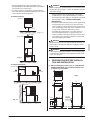
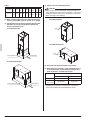
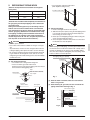
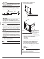
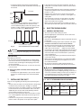
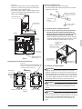
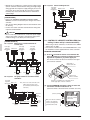
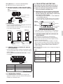
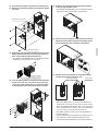
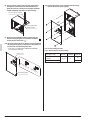
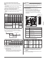
INSTALLATION MANUAL SYSTEM Inverter Air Conditioners MODELS Air Handling Unit FXTQ12PAVJU FXTQ18PAVJU FXTQ24PAVJU FXTQ30PAVJU FXTQ36PAVJU FXTQ42PAVJU FXTQ48PAVJU FXTQ54PAVJU English Français Español Read these instructions carefully before installation. Keep this manual in a handy place for future reference. This manual should be left with the equipment owner. Lire soigneusement ces instructions avant l’installation. Conserver ce manuel à portée de main pour référence ultérieure. Ce manuel doit être donné au propriétaire de l’équipement. Lea cuidadosamente estas instrucciones antes de instalar. Guarde este manual en un lugar a mano para leer en caso de tener alguna duda. Este manual debe permanecer con el propietario del equipo. VRV SYSTEM Inverter Air Conditioners CONTENTS 1. 2. 3. 4. 5. 6. 7. 8. 9. 10. 1. SAFETY CONSIDERATIONS ........................................... 1 BEFORE INSTALLATION .................................................. 3 SELECTING INSTALLATION SITE ................................... 3 PREPARATIONS BEFORE INSTALLATION AND INSTALLATION.................................................................. 4 REFRIGERANT PIPING WORK ....................................... 6 DRAIN PIPING WORK ...................................................... 7 INSTALLING THE DUCT ................................................... 8 ELECTRIC WIRING WORK .............................................. 8 WIRING EXAMPLE ........................................................... 9 FIELD SETTING AND TEST RUN .................................. 12 Installation manual • If refrigerant gas leaks during installation, ventilate the area immediately. Refrigerant gas may produce toxic gas if it comes in contact with fire. Exposure to this gas could cause severe injury or death. • After completing the installation work, check that the refrigerant gas does not leak throughout the system. • Do not install unit in an area where flammable materials are present due to risk of explosions that can cause serious injury or death. • Safely dispose all packing and transportation materials in accordance with federal/state/local laws or ordinances. Packing materials such as nails and other metal or wood parts, including plastic packing materials used for transportation may cause injuries or death by suffocation. SAFETY CONSIDERATIONS Read these “SAFETY CONSIDERATIONS for Installation” carefully before installing an air conditioner or heat pump. After completing the installation, make sure that the unit operates properly during the startup operation. Instruct the customer on how to operate and maintain the unit. Inform customers that they should store this Installation Manual with the Operation Manual for future reference. Always use a licensed installer or contractor to install this product. Improper installation can result in water or refrigerant leakage, electrical shock, fire, or explosion. Meanings of DANGER, WARNING, CAUTION, and NOTE Symbols: DANGER ................ Indicates an imminently hazardous situation which, if not avoided, will result in death or serious injury. WARNING .............. Indicates a potentially hazardous situation which, if not avoided, could result in death or serious injury. CAUTION ............... Indicates a potentially hazardous situation which, if not avoided, may result in minor or moderate injury. It may also be used to alert against unsafe practices. NOTE...................... Indicates situations that may result in equipment or property-damage accidents only. DANGER • Refrigerant gas is heavier than air and replaces oxygen. A massive leak can lead to oxygen depletion, especially in basements, and an asphyxiation hazard could occur leading to serious injury or death. • Do not ground units to water pipes, gas pipes, telephone wires, or lightning rods as incomplete grounding can cause a severe shock hazard resulting in severe injury or death. Additionally, grounding to gas pipes could cause a gas leak and potential explosion causing severe injury or death. WARNING • All phases of the field-installation, including, but not limited to, electrical, piping, safety, etc. must be in accordance with manufacturer's instructions and must comply with national, state, provincial and local codes. • Only qualified personnel must carry out the installation work. Installation must be done in accordance with this installation manual. Improper installation may result in water leakage, electric shock, or fire. • When installing the unit in a small room, take measures to keep the refrigerant concentration from exceeding allowable safety limits. Excessive refrigerant leaks, in the event of an accident in a closed ambient space, can lead to oxygen deficiency. • Use only specified accessories and parts for installation work. Failure to use specified parts may result in water leakage, electric shocks, fire, or the unit falling. • Install the air conditioner or heat pump on a foundation strong enough that it can withstand the weight of the unit. A foundation of insufficient strength may result in the unit falling and causing injuries. • Take into account strong winds, typhoons, or earthquakes when installing. Improper installation may result in the unit falling and causing accidents. • Make sure that a separate power supply circuit is provided for this unit and that all electrical work is carried out by qualified personnel according to local, state, and national regulations. An insufficient power supply capacity or improper electrical construction may lead to electric shocks or fire. • Make sure that all wiring is secured, that specified wires are used, and that no external forces act on the terminal connections or wires. Improper connections or installation may result in fire. • When wiring, position the wires so that the electric component box cover can be securely fastened. Improper positioning of the electric component box cover may result in electric shocks, fire, or the terminals overheating. • Before touching electrical parts, turn off the unit. 1 English • It is recommended to install a ground fault circuit interrupter if one is not already available. This helps prevent electrical shocks or fire. • The indoor unit is for R-410A. See the catalog for indoor models that can be connected. Normal operation is not possible when connected to other units. • Securely fasten the outside unit terminal cover (panel). If the terminal cover/panel is not installed properly, dust or water may enter the outside unit causing fire or electric shock. • Remote controller (wireless kit) transmitting distance can be shorter than expected in rooms with electronic fluorescent lamps (inverter or rapid start types). Install the indoor unit far away from fluorescent lamps as much as possible. • When installing or relocating the system, keep the refrigerant circuit free from substances other than the specified refrigerant (R-410A) such as air. Any presence of air or other foreign substance in the refrigerant circuit can cause an abnormal pressure rise or rupture, resulting in injury. • Do not change the setting of the protection devices. If the pressure switch, thermal switch, or other protection device is shorted and operated forcibly, or parts other than those specified by Daikin are used, fire or explosion may occur. CAUTION • Do not touch the switch with wet fingers. Touching a switch with wet fingers can cause electric shock. • Do not allow children to play on or around the unit to prevent injury. • Do not touch the refrigerant pipes during and immediately after operation as the refrigerant pipes may be hot or cold, depending on the condition of the refrigerant flowing through the refrigerant piping, compressor, and other refrigerant cycle parts. Your hands may suffer burns or frostbite if you touch the refrigerant pipes. To avoid injury, give the pipes time to return to normal temperature or, if you must touch them, be sure to wear proper gloves. • Install drain piping to proper drainage. Improper drain piping may result in water leakage and property damage. • Insulate piping to prevent condensation. • Be careful when transporting the product. • Do not turn off the power immediately after stopping operation. Always wait for at least 5 minutes before turning off the power. Otherwise, water leakage may occur. • Do not use a charging cylinder. Using a charging cylinder may cause the refrigerant to deteriorate. • Refrigerant R-410A in the system must be kept clean, dry, and tight. (a) Clean and Dry -- Foreign materials (including mineral oils such as SUNISO oil or moisture) should be prevented from getting into the system. (b) Tight -- R-410A does not contain any chlorine, does not destroy the ozone layer, and does not reduce the earth’s protection again harmful ultraviolet radiation. R-410A can contribute to the greenhouse effect if it is released. Therefore take proper measures to check for the tightness of the refrigerant piping installation. Read the chapter Refrigerant Piping and follow the procedures. • Since R-410A is a blend, the required additional refrigerant must be charged in its liquid state. If the refrigerant is charged in a state of gas, its composition can change and the system will not work properly. English • Indoor units are for indoor installation only. Outdoor units can be installed either outdoors or indoors. This unit is for indoor use. • Do not install the air conditioner or heat pump in the following locations: (a) Where a mineral oil mist or oil spray or vapor is produced, for example, in a kitchen. Plastic parts may deteriorate and fall off or result in water leakage. (b) Where corrosive gas, such as sulfurous acid gas, is produced. Corroding copper pipes or soldered parts may result in refrigerant leakage. (c) Near machinery emitting electromagnetic waves. Electromagnetic waves may disturb the operation of the control system and cause the unit to malfunction. (d) Where flammable gas may leak, where there is carbon fiber, or ignitable dust suspension in the air, or where volatile flammables such as thinner or gasoline are handled. Operating the unit in such conditions can cause a fire. • Take adequate measures to prevent the outside unit from being used as a shelter by small animals. Small animals making contact with electrical parts can cause malfunctions, smoke, or fire. Instruct the customer to keep the area around the unit clean. NOTE • Install the power supply and control wires for the indoor and outdoor units at least 3.5 feet away from televisions or radios to prevent image interference or noise. Depending on the radio waves, a distance of 3.5 feet may not be sufficient to eliminate the noise. • Dismantling the unit, treatment of the refrigerant, oil and additional parts must be done in accordance with the relevant local, state, and national regulations. • Do not use the following tools that are used with conventional refrigerants: gauge manifold, charge hose, gas leak detector, reverse flow check valve, refrigerant charge base, vacuum gauge, or refrigerant recovery equipment. • If the conventional refrigerant and refrigerator oil are mixed in R-410A, the refrigerant may deteriorate. • This air conditioner or heat pump is an appliance that should not be accessible to the general public. • As design pressure is 450 psi, the wall thickness of field-installed pipes should be selected in accordance with the relevant local, state, and national regulations. 2 2. FOR THE FOLLOWING ITEMS, TAKE SPECIAL CARE DURING CONSTRUCTION AND CHECK AFTER INSTALLATION IS FINISHED. BEFORE INSTALLATION WARNING • Entrust installation to the place of purchase or a qualified serviceman. Improper installation could lead to leaks and, in worse cases, electric shock or fire. • Use of unspecified parts could lead to the unit falling, leaks and, in worse cases, electric shock or fire. NOTE • Be sure to read this manual before installing the indoor unit. • Be sure to mount an air filter (part to be procured in the field) in the suction air passage in order to prevent water leaking, etc. The accessories needed for installation must be retained in your custody until the installation work is completed. Do not discard them. 1. Decide upon a line of transport. 2. Leave the unit inside its packaging while moving, until reaching the installation site. Where unpacking is unavoidable, use a sling of soft material or protective plates together with a rope when lifting, to avoid damage or scratches to the unit. Be sure to check the type of R410A refrigerant to be used before installing the unit. (Using an incorrect refrigerant will prevent normal operation of the unit.) For the installation of an outdoor unit, refer to the installation manual attached to the outdoor unit. 2-1 PRECAUTIONS • Be sure to instruct customers how to properly operate the unit (operating different functions, and adjusting the temperature) by having them carry out operations themselves while looking at the operation manual. • Do not install in locations where the air contains high levels of salt such as that near the ocean and where voltage fluctuates greatly such as that in factories, or in vehicles or vessels. 2-2 ACCESSORIES Check the following accessories are included with your unit. Name Clamp material (1) Insulation tube 4 pcs. 1 set Quantity Shape Large (3) 2 pcs. 2-3 OPTIONAL ACCESSORIES • This indoor unit requires one of the operation remote controls listed below. Remote controller Wired type Wireless type 3 If not properly done, what is likely to occur Are the indoor and outdoor The units may drop, vibrate units fixed firmly? or make noise. Is the refrigerant leak test It may result in insufficient finished? cooling. Is the unit fully insulated? Condensate may drip. Does drainage flow smoothly? Condensate may drip. Does the power supply The unit may malfunction or voltage correspond to that the components burn out. shown on the name plate? Are wiring and piping The unit may malfunction or correct? the components burn out. Incomplete grounding may Is the unit safely grounded? result in electric shocks. Is wiring size according to The unit may malfunction or specifications? the components burn out. Is something blocking the air It may result in insufficient outlet or inlet of either the cooling. indoor or outdoor units? Are refrigerant piping length The refrigerant charge in and additional refrigerant the system is not clear. charge noted down? Items to be checked Check Also review the “SAFETY CONSIDERATIONS”. b. Items to be checked at time of delivery Items to be checked Did you explain about operations while showing the operation manual to your customer? Did you hand the operation manual and warranty over to your customer? Did you explain to your customer how to maintain and clean local procurements such as the air filter, suction grille, and air outlet grille? Did you hand manuals of local procurements (in case equipped) over to your customer? 3. Check SELECTING INSTALLATION SITE CAUTION (Other) • Operation manual • Installation manual Small (2) 2 pcs. a. Items to be checked after completion of work BRC1E71, BRC1D71 BRC4C82 • If you think the humidity inside the installation space might exceed 86°F and RH80%, reinforce the insulation on the unit body. Use glass wool or polyethylene foam as insulation so that the thickness is more than 2 in. and fits inside the installation space opening. (1) Select an installation site where the following conditions are fulfilled and that meets with your customer’s approval. • Where optimum air distribution can be ensured. • Where nothing blocks air passage. • Where condensate can be properly drained. • Where the supports are strong enough to bear the indoor unit weight. • Where the false ceiling is not noticeably on an incline. • Where sufficient clearance for maintenance and service can be ensured. (Refer to Fig. 1-1 and Fig. 1-2) English • Where piping between indoor and outdoor units is possible within the allowable limit. (Refer to the installation manual for the outdoor unit.) • If a return-air duct is not installed, carefully select the place and method of product installation so that air flow into the product will not be blocked. WARNING • When installing the unit horizontally, be sure to tilt the unit in the direction shown in Fig. 1-2. If the unit is tilted in any other way, water can leak. • Ensure sufficient space for the bottom of the product (H dimensions) so that a downward slope of 1/100 can be maintained for drain piping, as described for the intake duct installation and in “6. DRAIN PIPING WORK”. If installed vertically (Top view) [ PRECAUTION ] • Install the indoor and outdoor units, power supply wiring and connecting wires at least 3.5 ft. away from televisions or radios in order to prevent image interference or noise. (Depending on the radio waves, a distance of 3.3 ft. may not be sufficient to eliminate the noise.) • If installing the wireless kit in a room with electronic fluorescent lighting (inverter or rapid start type), the remote controller’s transmission distance may be shortened. Indoor units should be installed as far away from fluorescent lighting as possible. 24 or more (length : in.) Air outlet (Front view) DANGER • Do not install unit in an area where flammable materials are present due to the risk of an explosion resulting in serious injury or death. WARNING • If the supporting structural members are not strong enough to take the unit’s weight, the unit could fall out of place and cause serious injury. Fig. 1-1 Air inlet H 4. If installed horizontally (1) When installing the product, refer to “3. SELECTING INSTALLATION SITE” and consider the product size as shown Fig. 2 and Table 1. (Front view) Air inlet PREPARATIONS BEFORE INSTALLATION AND INSTALLATION Air outlet Fig. 2 H 1 (Side view) D C B E 11 A 24 or more Gas line H 3-1/4 Fig. 1-2 F G 1-1/8 Liquid line 1-3/16 H (1-3/16) 2-7/8 I (1-3/16) (length: in.) English 4 Table 1 Model 12 · 18 type 24 · 30 · 36 · 42 · 48 · 54 type (4) Check if the unit is horizontally level. A 463/4 531/4 B 22 24 C 171/2 20 D 191/2 22 E 10 12 F G H I 14- 11- 17- 171/2 15/16 1/8 15/16 14- 11- 19- 191/2 15/16 5/8 15/16 (2) Make sure the range of the unit’s external static pressure is not exceeded. (up to 0.5 in.W.C. at “H” speed.) CAUTION • Make sure the unit is installed level using a level tube: four sides. (One thing to watch out for in particular is if the unit is installed so that the slope is not in the direction of the drain piping, this might cause leaking.) If installed vertically (3) Condensation may form on the product during COOL operation. Be sure to provide (field supplied) and install a second drain pan. Level If installed vertically If installed horizontally Level Second drain pan Drain piping If installed horizontally (5) Secure the unit firmly to prevent it from falling. (6) When the unit is installed in a hot and humid place, it is recommended to use the following drain pan insulation kit, which is an optional accessory. Drain pan insulation Kit Second drain pan Vertically Horizontally 12 · 18 type DPI 36-42/20 DPIH 36-42 24 · 30 · 36 · 42 · 48 · 54 type DPI 48-60/20 DPIH 48-61 Drain piping • Regarding the attachment of the drain pan insulation kit, refer to the installation manual provided with the kit. 5 English 5. REFRIGERANT PIPING WORK 〈Observe the requirements listed below for refrigerant piping sizes.〉 Liquid Gas 12 · 18 type 1/4 in. 1/2 in. 24 · 30 · 36 · 42 · 48 · 54 type 3/8 in. 5/8 in. 〈Execute heat insulation work completely on both sides of the gas piping and the liquid piping or else a water leakage might result. Failing to insulate the pipes may cause leaking or burns. And be sure to use the insulation which can withstand such temperatures of 248°F or more for the equalizer pipe and the gas piping. Reinforce the insulation on the refrigerant piping according to the installation environment. If the temperature or humidity in the product installation location might reach 86°F or 80%, respectively. Condensation may form on the surface of the insulation.〉 CAUTION Follow the points at below. • Use a tube cutter and flare suitable for the type of refrigerant. • To prevent dust, moisture or other foreign matter from infiltrating the piping, either pinch the end or cover it with tape. • Do not allow anything other than the designated refrigerant to get mixed into the refrigerant circuit, such as air. If any refrigerant gas leaks while working on the unit, immediately ventilate the room. • Cut off the pipe end with a tube cutter. (Both liquid line and gas line) Cut with a tube cutter (2) Connect the piping. 1. Remove the upper and lower front panels. 2. Slide the front panel (lower) along the field piping until it is far enough away that it will not be affected by heat from brazing, as shown in Fig. 3. 3. Braze up to the field piping fitting port while cooling the sensor and the thermal insulation. 4. Close the upper and lower front panels once heat from the brazed areas has dissipated. NOTE • When brazing the field piping, cover the pipe insulation and the thermal sensor inside the insulation with a damp cloth to prevent any damage to the sensor or the insulation. Otherwise, the sensor may be damaged by heat of brazing, which lead to a failure of normal operation. Field piping fitting port (brazed) Field piping (1) Cut off the spin closure. • The outdoor unit is charged with refrigerant. • This coil contains gas under 150 P.S.I.G. Release pressure from the gas piping pressure-release device before initiating piping work. Cap After the work is finished, try to repair. Sharp object (1) Remove (2) Push Fig. 3 (3) After the work is finished, make sure to check that there is no gas leak. Detail Pressure release device Front panel (4) After checking for gas leaks, be sure to insulate the piping connections referring to Fig. 4. Do not leave a gap Gas piping Gas piping Liquid piping Air handler Fig. 4 English Piping heat insulation material Liquid piping 6 (1) Install drain piping as described Fig. 6. CAUTION • Be sure to insulate any field piping all the way to the piping connection inside the unit. Any exposed piping may cause condensation or burns if touched. In case of vertical installation • When brazing the refrigerant piping, perform nitrogen replacement first, or perform the brazing while feeding nitrogen into the refrigerant piping. (Refer to Fig. 5) Pressure-reducing valve Part to be brazed Nitrogen Refrigerant piping Taping hands valve Nitrogen Fig. 5 CAUTION Secondary drain piping connection hole Fig. 6-1 Primary drain piping connection hole In case of horizontal installation • When brazing piping while feeding nitrogen inside the piping, make sure to set the nitrogen pressure to 2.9 psi or less using the pressure reducing valve. (This pressure is such that a breeze is blown to your cheek.) DANGER • Use of oxygen could result in an explosion resulting in serious injury or death. Only use dry nitrogen gas. • Refrigerant gas may produce toxic gas if it comes in contact with fire such as from a fan heater, stove or cooking device. Exposure to this gas could cause severe injury or death. NOTE • Do not use flux when brazing refrigerant piping. Therefore, use the phosphor copper brazing filler metal (BCuP) which does not require flux. Flux has an extremely negative effect on refrigerant piping systems. For instance, if chlorine based flux is used, it will cause piping corrosion. Flux containing fluorine will damage refrigerant oil. 6. DRAIN PIPING WORK CAUTION • Make sure all water is out before making the duct connection. Fig. 6-2 Reinstall the cover. Remove the cover Primary drain piping connection hole Secondary drain piping connection hole • Perform drain work so that the unit is drained thoroughly. (Be sure to insulate the following 2 locations since condensation may cause water leakage.) • Drain piping • Drain socket • The drain pan has connections for a primary and secondary drain. • Use 3/4 PVC piping for drain piping connections. • Keep piping runs short with a downward slope of at least 1/100 to prevent air pocket from forming. • Be sure to install a drain trap at the drain outlet since the inside of the unit is at negative pressure relative to atmospheric pressure during operation. • Knock out the plastic seal with a screwdriver and a hammer. (Refer to Fig. 7) NOTE • In case of horizontal installation, carefully knock out the plastic seal. Operation without opening the drain piping connection hole causes water leakage. 7 English • To keep the piping from becoming clogged with dirt, avoid bends where possible and install so that traps can be cleaned. Air handler At least 4 in. At least 3 in. Fig. 7 • Observe the following guidelines when installing concentrated drain piping. Select the thickness of the concentrated drain piping to reflect the capacity of the machine to which it will be connected. (Install a drain trap for each indoor unit.) (Refer to Fig. 8) • If the metal duct passes through a metal lath, wire lath, or metal plate of a wooden structure, isolate the duct from the wall electrically. • Be sure to heat-insulate the duct to prevent the formation of condensation. (Material: Glass wool or polyethylene foam; thickness: 1 inch.) • Explain to the customer how to operate and clean fieldsupplied components such as air filters, air inlet grilles, air outlet grilles. • To prevent drafts, locate the air outlet grille on the indoor side so that warm air from the outlet does not come into direct contact with room occupants. • When an electric heater (optional) is installed, use metal duct and wrap the duct with a glass-wool insulation material. 8. ELECTRIC WIRING WORK 8-1 GENERAL INSTRUCTIONS At least 4 in. Fig. 8 Concentrated drain piping (Use a downward slope of at least 1/100.) CAUTION • Water accumulating in the drain piping can cause the drain to clog. 〈PRECAUTIONS〉 Drain piping connections • Do not connect the drain piping directly to sewage piping that smell of ammonia. The ammonia in the sewage might enter the indoor unit through the drain piping and corrode the heat exchanger. • Do not twist or bend the drain hose, as excessive force may cause it to leak. • Shut off the power before doing any work. • All field supplied parts and materials, electric works must conform to local codes. • Use copper wire only. • See also the “Wiring Diagram Label” located inside the unit’s fan housing. • For details on hooking up the remote controller, refer to the “REMOTE CONTROLLER INSTALLATION MANUAL” • All wiring must be performed by an authorized electrician. • This system consists of multiple indoor units. Mark each indoor unit as unit A, unit B . . . , and be sure the terminal board wiring to the outdoor unit and Branch Selector unit are properly matched. If wiring and piping between the outdoor unit and an indoor unit are mismatched, the system may cause a malfunction. • Install a wiring interrupter or ground-fault circuit interrupter for the power wiring. • Make sure the ground resistance is no greater than 100Ω. • To avoid short circuiting the power supply wire, be sure to use insulated terminals. • Do not turn on the power supply (wiring interrupter or ground-fault circuit interrupter) until all other work is done. DANGER (2) After piping work is finished, check drainage flows smoothly. • Gradually insert approximately 1 quart of water into the drain pan to check drainage in the manner described below. • Do not ground units to water piping, telephone wires or lightning rods because incomplete grounding could cause a severe shock hazard resulting in severe injury or death, nor to gas piping because a gas leak could result in an explosion which could lead to severe injury or death. 7. 8-2 LIST OF STANDARD WIRING EQUIPMENT INSTALLING THE DUCT Exercise care regarding the following when performing duct work. • Verify that duct work does not exceed the unit’s setting range of external static pressure (up to 0.5 Wg at “H” speed). • Install canvas ducts at air outlets and inlets so that vibrations from the main unit are not transmitted to ducts or the floor. Additionally, line the duct with sound-absorbing material (heat insulation material) as necessary. • Be sure to install a optional air filter to the product’s air inlet or to a field-supplied air inlet inside the air passage on the suction side. • Perform the curing and other work during duct welding so that the inside of the product is not exposed to spatter. English Power supply wiring (including ground wire) Field fuses 15A Transmission wiring Remote controller wiring Size Wire Size Must comply with local codes. 2-conductor, stranded, nonshielded copper/ PVC or vinyl jacket AWG18 – 16 8 NOTES 1. If the wiring is in a place where people it can be easily touched by people, install a ground-fault circuit interrupter to prevent electric shock. 2. When using a ground-fault circuit interrupter, make sure to select one useful also to protection against overcurrent and short-circuit. When using a ground-fault circuit interrupter only for grounding device, make sure to use a wiring interrupter together. • The length of the transmission wiring and remote controller wiring are as follows. If the wiring gets too hot due to loose power-supply wiring, use the following precautions: • For wiring, use the designated power supply wiring and connect firmly, then secure to prevent outside pressure being exerted on the terminal board. • Use the correct screwdriver for tightening the terminal screws. If the blade of screwdriver is too small, the head of the screw might be damaged, and the screw will not be properly tightened. • If the terminal screws are tightened too hard, screws might be damaged. • Refer Table 2 for the tightening torque of the terminal screws. Length of the transmission wiring and remote controller wiring Table 2 Outdoor unit – Indoor unit Max. 3280 ft. (Total wiring length: 6560 ft.) Indoor unit – Remote controller Max. 1640 ft. Terminal block Tightening torque (ft · lbf) Remote controller / transmission wiring terminal block (6P) (10P) Power supply wiring terminal block (3P) 0.58 – 0.72 0.87 – 1.06 8-3 ELECTRICAL CHARACTERISTICS (1) Remove the front panel (upper). Units Model 12 type 18 type 24 type 30 type 36 type 42 type 48 type 54 type Hz Volts 208/ 230 60 Power supply Fan motor Voltage range MCA HP Min. 187 Max. 229/ Min. 207 Max. 253 1.1 1.9 1.6 2.4 3.3 4.0 6.0 8.0 MOP 1/2 15 3/4 Top panel FLA 0.9 1.5 1.3 1.9 2.6 3.2 4.8 6.4 Electric components box cover Low-voltage hole High-voltage hole MCA: Minimum Circuit Amps (A) MOP: Max Overcurrent Protective Device (A) HP: Fan motor output (HP) FLA: Full Load Amps (A) (2) Remove the electric component box cover. 9. WIRING EXAMPLE Terminal block (6P) 9-1 HOW TO CONNECT WIRINGS 〈Precautions when laying power supply wiring〉 • Wiring of different thicknesses cannot be connected to the power supply wiring terminal block. Slack in the power supply wiring may cause abnormal heat. • Use sleeve-insulated round crimp-style terminals for connections to the power supply wiring terminal block. When none are available, connect wires of the same diameter to both sides, as shown in the figure. Terminal block (3P) Insulation sleeve Round crimp-style terminal Connect wires of the same gauge to both sides. 9 Do not connect wires of the same gauge to one side. Electric wire Do not connect wires of different gauges. (3) Pass the power supply wiring and the ground wire through the top panel’s high-voltage hole (requires use of conduit) and pass the remote controller wiring and transmission wiring through the top panel’s low-voltage hole. • Pass the included insulation tube through the hole in the panel before connecting the electric wires and the ground wire to the terminal block (3P) shown in Fig. 9. • Pass the included insulation tube through the hole in the panel before connecting the remote controller wiring and transmission wires to the terminal block (6P) shown English in Fig. 10. • Then secure them in place with the included clamp material (1) as shown in Fig. 10 to protect them from external force from outside the unit. • If the power supply voltage is 208V, change the transformer wire connection from the 240V terminal to the 208V terminal. (Refer to Fig. 11) How to use insulation tube. • Use the insulation tube to cover the wiring. • Joint the insulation tube with the tape and cut off the tube sticking out of the unit. Tape Insulation tube large (3) Terminal block (3P) Insulation tube small (2) Insulation tube Cut off the sticking out of the unit. L2 L1 POWER (4) Install the electric component box cover. Fig. 9 Terminal block (6P) Transformer (5) Pass the power supply wiring and the ground wire through the conduit (conduit should be field supplied). The hole for running wires through should be sealed completely to prevent air from entering. * When installing an optional electric heater kit, run both the power supply wiring and ground wire of the electric heater kit through the conduit. (Refer to 10-5 (8)) Pass through the conduit Remote controller and transmission wiring Insulation tube Clamp material (1) (accessory) Fig. 10 Power supply wiring and ground wire Clamp material (1) (accessory) Changing the transformer wire connection Connector (Connect the wire to the 208V terminal. Be sure to insert the wire securely until a clicking sound is produced.) DANGER Cap (Change the connection.) Wire (Red) COM 208V 240V Wire (Red) COM 208V 240V Connector Cap (6) Install the front panel (upper). • Use only specified wire and connect wires to terminals tightly. Be careful that wires do not place external stress on terminals. Keep wires in neat order so as to not to obstruct other equipment. Make sure that the electric component box cover closes tightly. Incomplete connections could result in overheating, and in worse cases, electric shock or fire. WARNING • Never connect power supply wiring to the terminal block for remote controller wiring as this could damage the entire system. 230V power supply (factory set)® Fig. 11 208V power suppy® CAUTION • When doing the wiring, make sure the wiring is neat and does not cause the electric component box cover to stick up, then close the cover firmly. When attaching the electric component box cover, make sure you do not pinch any wires. English 10 • Outside the air conditioners, separate the low voltage wiring (remote controller and transmission wiring) and high voltage wiring (ground wire and power supply wiring) by at least 5 in. so that they do not pass through the same place together. Proximity may cause electrical interference, malfunctions, and breakage. [ PRECAUTIONS ] • Refer to the “REMOTE CONTROLLER INSTALLATION MANUAL” on how to install and lay the wiring for the remote controller. • See also the “Wiring Diagram Label” located inside the unit’s fan housing. • Connect the remote controller and transmission wiring their respective terminal blocks. No. 3 system When including BS unit Power supply single phase 60Hz 208/230V Outdoor unit IN/D OUT/D F1 F2 F1 F2 L1 L2 Indoor unit A P1 P2 • Do not, under any circumstances, connect the power supply wiring to the remote controller or transmission wiring terminal block. Doing so can destroy the entire system. Power supply single phase 60Hz 208/230V Outdoor unit L1 L2 • When using 2 remote controllers, one must be set to “MAIN” and the other to “SUB”. • If the remote controller to be used is Model BRC1E71, read the installation manual supplied with the remote controller. Power supply single phase 60Hz 208/230V L1 L2 Remote controller (option) 9-2 CONTROL BY 2 REMOTE CONTROLLERS (Controlling 1 indoor unit by 2 remote controllers) [ WIRING EXAMPLE ] No. 1 system When using 1 remote controller for 1 indoor unit IN/D OUT/D IN/D F1 F2 F1 F2 P1 P2 F1 F2 T1 T2 CAUTION Power supply single phase 60Hz 208/230V BS unit L1 L2 L1 L2 OUT/D MAIN/SUB CHANGEOVER F1 F2 F1 F2 (1) Insert a screwdriver into the recess between the upper and lower part of remote controller and, working from the 2 positions, pry off the upper part. The remote controller PC board is attached to the upper part of remote controller. L1 L2 L1 L2 P1 P2 F1 F2 T1 T2 Indoor unit A P1 P2 F1 F2 T1 T2 P1 P2 Remote controller (option) No. 2 system Upper part of remote controller P1 P2 Remote controller (option) Remote controller (option) Lower part of remote controller For group control or use with 2 remote controllers Insert the screwdriver here and gently work off the upper part of remote controller. Power supply single phase 60Hz 208/230V Outdoor unit Note) There is not need to set the indoor unit address when using group control. (It is automatically set when the power is turned on.) L1 L2 IN/D OUT/D F1 F2 F1 F2 P1 P2 F1 F2 T1 T2 L1 L2 P1 P2 F1 F2 T1 T2 L1 L2 P1 P2 F1 F2 T1 T2 Indoor unit B Indoor unit A P1 P2 Remote controller (option) 11 P1 P2 F1 F2 T1 T2 Most downstream Indoor unit Indoor unit B P1 P2 L1 L2 L1 L2 Case of group control P1 P2 Most downstream indoor unit P1 P2 (MAIN) (SUB) Remote controller (option) (2) Turn the MAIN/SUB changeover switch on one of the two remote controller PC boards to “S”. (Leave the switch of the other remote controller set to “M”.) (Factory setting) S M Remote controller PC board Only one remote controller needs to be changed if factory settings have remained untouched. S M For use with 2 remote controllers English Wiring Method (See ‘‘8. ELECTRIC WIRING WORK’’) 10. FIELD SETTING AND TEST RUN (3) Remove the electric component box cover. 〈Field settings may have to be performed using the remote controller, depending on the type of installation.〉 (4) Add remote controller 2 (SUB) to the terminal block for remote controller (P¹, P²) in the electric component box. (There is no polarity.) P1 P2 F1 F2 T1 T2 REMOTE CONTRL TRANSMISSION WIRING FORCED OFF Remote controller wiring terminal block Remote controller 2 (SUB) Remote controller 1 (MAIN) [ PRECAUTIONS ] • Crossover wiring is needed when using group control and 2 remote controllers at the same time. • Connect the indoor unit at the end of the crossover wire (P¹, P²) to remote controller 2 (SUB). Indoor unit 1 Max. No. of indoor units Indoor unit 2 (1) Make sure the electric component box covers are closed on the indoor and outdoor units. (2) Depending on the type of installation, make the field settings from the remote controller after the power is turned on, following the “Field Settings” manual which came with the remote controller. • The settings can select “Mode No.”, “FIRST CODE NO.” and “SECOND CODE NO.”. • The “Field Settings” included with the remote controller lists the order of the settings and method of operation. SECOND CODE NO. Mode No. FIRST CODE NO. FIELD SET MODE SETTING • Lastly, make sure the customer keeps the “Field Settings” manual, along with the operating manual, in a safe place. 10-1 SETTINGS WHEN USING THE OPTIONAL REMOTE SENSOR Crossover wire (P1.P2) Remote controller 1 (MAIN) Remote controller 2 (SUB) 9-3 REMOTE CONTROL (FORCED OFF AND ON/ OFF OPERATION) • Connect input lines from the outside to the terminals T¹ and T² on the terminal block (6P) for remote controller to achieve remote control. • See the “10. FIELD SETTING AND TEST RUN” for details on operation. P1 P2 F1 F2 T1 T2 REMOTE CONTRL TRANSMISSION WIRING FORCED OFF This product does not include an air inlet thermistor. It uses a remote controller thermistor for control purposes. For this reason, it is necessary to install an optional remote thermistor in the following cases: • When the remote controller will be installed at a location where it cannot accurately measure the indoor temperature. • When using a remote controller without a built-in thermistor (simple remote controller, wireless remote controller, no remote controller). When using an optional remote sensor, change the settings as described Table 3: Table 3 Mode No. To use both the remote controller thermistor and the remote sensor To use only the remote sensor To use only the remote controller thermistor Input A Wire specification Gauge 01 10 (20) 2 02 03* * factory set Sheathed vinyl cord or cable (2 wires) AWG18 – 16 Length External terminal FIRST SECOND CODE NO. CODE NO. Max. 328 ft. Contact that can ensure the minimum applicable load of 16 V DC, 1 mA. 9-4 CENTRALIZED CONTROL • For centralized control, it is necessary to designate the group No. For details, refer to the manual of each optional controller for centralized control. English 12 (2) Insert the air filter as far as it can go. 10-2 REMOTE CONTROL SETTING • Forced off and ON/OFF operation should be selected by selecting the SECOND CODE NO. as shown in Table 4. Table 4 External ON/OFF input Mode No. Forced off ON/OFF operation 12 (22) FIRST SECOND CODE NO. CODE NO. 01* 1 02 * factory set • Input A of forced off and ON/OFF operation work as shown in Table 5. Table 5 Forced off Input A “on” to force a stop (remote controller reception prohibited) Input A “off” to allow remote controller ON/OFF operation Unit operated by changing input A from “off” to “on” Unit stopped by changing input A from “on” to “off” Air filter (optional accessories) 10-5 INSTALLATION OF THE ELECTRIC HEATER KIT WARNING 10-3 SETTING THE FILTER SIGN DISPLAY INTERVAL • Explain the following to the customer if the filter dirt settings have been changed. • The filter sign display time is set to 2500 hours (equivalent to 1 year’s use) when shipped. • The settings can be changed to not display. • When installing the unit in a dusty place, set the filter sign display time to shorter intervals (1,250 hours). • Explain it to the customer that the filter needs to be cleaned regularly to prevent clogging and also the time that is set. Mode No. FIRST CODE NO. 0 10 (20) 1 (low/high) Filter dirt Displayed time (units: hours) Filter sign display SECOND CODE NO. 01 02 low high 2500/ 10000/ 1250 5000 ON OFF • All phases of the electrical installation must comply with national, state, provincial, and local codes. • When connecting an electric heater, be sure to install an earth leakage circuit breaker procured locally. • If an earth leakage circuit breaker is not installed, electric shock or fire may result. • Regarding the rated current of the earth leakage circuit breaker to be installed, refer to the H.M.C.A. value indicated on the manufacturer’s label or in a technical document. • The recommended rapid sensitive current and tripping time are indicated below. Recommended specifications of circuit breaker Rapid sensitive current 30mA Tripping time 0.1sec • Purchase and install the air filter as in Table 6. • Purchase and install the electric heater kit as in Table 7. • Also refer to the installation and operating instructions that come with the electric heater kit. • The indoor unit fan operates at H speed during HEATER operation. Table 6 Table 7 3 10-4 INSTALLATION OF THE OPTIONAL AIR FILTER 12 · 18 type 24 · 30 · 36 · 42 · 48 · 54 type Electric heater kit model name Air filter FIL 36-42 FIL 48-61 (1) Take off the part on the bottom of the front panel. Model HKR03 HKR05C HKR06 HKR08C HKR10C HKR15C HKR20C 12 type 18 type 1 24 type 1 30 · 36 type 1 1 42 type 1 1 1 1 2 48 · 54 type 1 1 1 1 2 2 1 : Auxiliary and Heat Pump Lockout: Electric heater operation with heat pump is allowed. : Heat Pump Lockout: Only electric heater operation is allowed. Heat pump and electric heater cannot operate at the same time. 2 : Heat Pump Lockout: Only electric heater operation is allowed. Heat pump and electric heater cannot operate at the same time. In addition, acceptable 2 step heating control. 13 English (1) Turn off power supply to all indoor and outdoor units. (2) Remove the front panel (upper) and the electric heater slot cover. (5) Install the circuit breaker mounting bracket removed in step (3) into the blower deck. * The HKR-03 and HKR-06 have no circuit breaker mounting bracket; Procure and install a circuit breaker. Electric heater slot cover (6) Connect the relay connector of the heater kit to the relay connector of the product. Disconnect the empty connector connected to the relay connector of the product. Front panel (upper) (3) Remove the circuit breaker mounting bracket from the heater element in the electric heater kit by removing the 2 screws. (Do not remove the harness) * The HKR-03 and HKR-06 have no circuit breaker mounting bracket, so proceed from the next step. Heater element Circuit breaker mounting bracket (7) Check that the circuit breaker is turned off, and connect the heater kit to the wiring on site. Power supply wiring Ground wire (4) Insert the heater element in the electric heater kit into the electric heater slot, and use six of the screws taken out in step (2) to install it. When doing so, check that airflow is matched. Refer to the heater kit for details of airflow. HKR-05C, 08C, 10C HKR-15C, 20C * When using HKR-03, 06, connect the power supply wire to the terminal block located inside the main unit of the heater element. * When using HKR-03, 05C, 06, 08C, 10C, connect the ground wire to the terminal block for indoor units. (The terminal block is located on the air outlet side of the blower deck.) *If the HKR-15C/20C is used, connect the ground wire to the both terminals. The terminal blocks for ground wire are located on the air outlet side of the indoor unit blower deck and on the circuit breaker mounting bracket of the electric heater kit. English 14 (8) Pass the power supply wiring and the ground wire through the conduit (conduit should be field supplied). The hole for running wires through should be sealed completely to prevent air from entering. (11) Confirm that there are no mistakes with the wiring, and install the front panel (upper). Pass through the conduit Power supply wiring and ground wire (9) Select the corresponding electric heater from the electrical wiring diagram and mark the checkbox ( for the electric heater with “ ”. ) (10) Open the knock hole of the plastic cover provided for the front panel (upper) so that the circuit breaker will be turned on and off through the hole. * This step is not required for HKR-03 and HKR-06. Proceed to the next step. Plastic cover (12) On-site setting of heater (12) -1 Electric heater capacity setting Electric Heater capacity setting (Optional kit) HKR-03, 05, 06, 08, 10, 15, 20 type Without heater Mode No. FIRST CODE NO. 11 (21) 5 SECOND CODE NO. 01 03* * factory set HK R-0 5C , 08 C, 10 C HK R-1 Front panel (upper) 15 5C , 20 C English (12) -2 Electric heater operating mode setting 〈When electric heater is used in “Heat Pump lockout mode”〉 • Check the heater capacity. (Select heater marked with “ ” or “ 2” in Table 8.) • Perform on-site setting using the remote controller. • Set the “heat pump lockout mode” using the outdoor unit. (Refer to the service manual for the outdoor unit.) 〈When used as “Auxiliary electric heater”〉 • Check the heater capacity. (Select heater marked with “ 1” in Table 8.) • Perform on-site setting using the remote controller. Table 8 WARNING • If the unit is installed with an electric heater, install the optional product at a location where it is not exposed directly to the heat from the electric heater. Direct exposure to heat can result in an equipment malfunction or fire. (2) Connect the wires • Run the wires through the low-voltage hole. • Connect the wires to the terminal block (10P) of the product. The terminal Nos. for wire connection are shown below. Refer to the information as needed. Terminal Nos. are indicated on the name plate for the terminal block. Electric heater kit model name Model HKR03 HKR05C HKR06 HKR08C HKR10C HKR15C Terminal block (10P) HKR20C 1 24 type 1 30 · 36 type 1 1 42 type 1 1 1 1 2 48 · 54 type 1 1 1 1 2 Electric Heater kit setting (Optional kit) Mode No. FIRST CODE NO. 2 1 18 type 2 3 4 5 6 7 8 9 10 12 type SECOND CODE NO. Heat Pump lock out mode 01* Auxiliary electric heater & Heat Pump Lockout mode available 11 (21) 03 3 Terminal No. Input/output signal * factory set 1, 2 Outputs: indoor unit ON signal. (AC 24V) (12) -3 Electric heater ON/OFF temperature setting 3, 4 • While in heating operation, the heater control (ON/OFF) is conducted as shown below; Outputs: indoor unit cooling THERMO ON signal. (AC 24V) 5, 6 Receives input: Air purifier operation ON signal. (dry contact) 7, 8 Receives input: Humidifier operation ON signal. (dry contact) 9, 10 Receives input: Forced closure of Indoor Unit Electronic Expansion Valve during cooling operation. (dry contact) Set temperature ON OFF <Toff: F°> <Ton: F°> (3) On-site setting of air purifier/humidifier • Perform on-site setting using the remote controller. Mode No. Mode No. FIRST CODE NO. FIRST CODE CODE NO. 01* 02 03 04 05 06 <Ton> -7.2 -6.3 -5.4 -4.5 -3.6 -2.7 <Toff> -3.6 -2.7 -1.8 -0.9 0 0.9 10 (20) 7 SECOND CODE NO. 14 (24) 14 (24) * factory set 10-6 SETTING FOR LOCAL SUPPLIED OPTION. (1) Installation of the humidifier, economizer and air purifier (UV lamp) • Humidifier, economizer and air purifier (UV lamp) are sold separately. For the method of installation, refer to the manual provided with each optional product. English 4 5 01 02 FAN SPEED UNDER OPERATING purifier and humidifier Refer to remote controller setting SPEED H* FAN RESIDUE TIME FOR HUMIDIFIER 30 [sec] 60* [sec] 03 120 [sec] * factory set 10-7 SETTINGS FOR SEPARATELY SOLD ACCESSORIES • See the instruction manuals included with optional accessories for the necessary settings. 16 〈When using a wireless remote controller〉 • A wireless remote controller address needs to be set when using a wireless remote controller. See the installation manual included with the wireless remote controller for details on how to make the settings. Perform a test run according to the outdoor unit’s installation manual. • The operation lamp of the remote controller will flash when a malfunction occurs. Check the malfunction code on the liquid crystal display to identify the point of trouble. An explanation of malfunction codes and the corresponding trouble is provided in “CAUTION FOR SERVICING” of the outdoor unit. If the display shows any of the following, there is a possibility that the wiring was done incorrectly or that the power is not on, so check again. Remote control display “ ” display Content • There is a short circuit at the FORCED OFF terminals (T¹, T²). “ U3 ” display • The test-run has not been performed. “ U4 ” display “ UH ” display • The power on the outdoor unit is off. • The outdoor unit has not been wired for power supply. • Wiring is incorrect for the transmission wiring and / or FORCED OFF wiring. • The transmission wiring is cut. “ UF ” display No display • Reversed transmission wiring • The power on the indoor unit is off. • The indoor unit has not been wired for power supply. • Wiring is incorrect for the remote controller wiring, the transmission wiring and / or the FORCED OFF wiring. • The remote controller wiring is cut. CAUTION • Always stop the test run using the remote controller to stop operation. 17 English 3P250363-2B EM09A034A (1011) FS


![Daikin - [Klima], aire acondicionado](http://vs1.manualzilla.com/store/data/005774952_1-8d861f394f8ece21c166c1fcfde6f130-150x150.png)