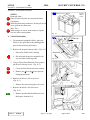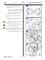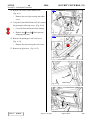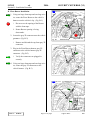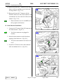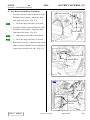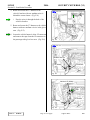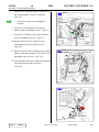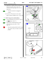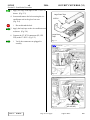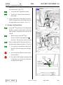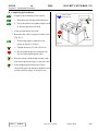
1
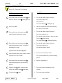
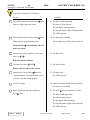
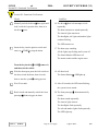
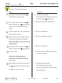
Document # 2064 (TMS) 9/26/03
SCION
xA
2004 −
SECURITY WITH RKE (V3)
Section I − Installation Preparation
Part Number: 08586−52970
Section I − Installation Preparation
Kit Contents
Item #
1
2
3
4
5
6
Quantity Reqd.
1
1
2
1
1
1
Description
Wire Harness
V3 Security ECU
Remote Control Transmitters
Piezo Buzzer
Status Monitor
Butyl Tape
Special Chemicals
3MTM Prep Solvent−70
Household Win dex
Cleaning Fluid
Glass Cleaner
General Applicability
Note: SCION xA with power door locks, only.
Recommended Sequence of Application
Hardware Bag Contents
Item #
1
2
3
4
5
6
7
8
Quantity Reqd.
1
3
1
10
25
1
2
1
Description
ECU Mounting Bracket
Large Foam Tape Strips (2 per.)
Small Foam Tape Strip (1 per.)
Large Wire Ties
Medium W ire Ties
Owner’s Manual
Warning Labels
Warranty Card
Item #
1
2
3
4
*Mandatory
Legend
STOP
Additional Items Required For Installation
Item #
1
Quantity Reqd.
Accessory
TVIP
Satellite Receiver
Audio
Door Sill Applique
(SB)
Description
STOP: Damage to the vehicle may occur. Do not
proceed until process has been complied with.
OPERATOR SAFETY: Use caution to avoid risk of
injury.
CRITICAL PROCESS: Proceed with caution to ensure
a quality installation.
GENERAL PROCESS: This highlights specific
processes to ensure a quality installation.
Conflicts
Note: This kit may not be installed in vehicles wit h Factory
TDS.
TOOLS & EQUIPMENT: Calls out the specific tools
and equipment recommended for this process.
Recommended Tools
Safety Tools
Safety Glasses
Safety Gloves
Vehicle Protection
Optional
Blankets, Part Boxes
Special Tools
None
Installation Tools
Screwdriver
Screwdriver
Scrwdriver
Socket
Socket Extension
Wrench
Torque Wrench
Nylon Panel Removal Tool
Phillips # 2, (or Tip)
Flat Blade, Small
Jeweler s
10 mm
3"
10 mm
36 lbf −in
e.g. Panel Pry Tool #1
Toyota SST # 00002−06001−01
Side Cutters
Utility Knife
Pliers
Issue: A
06/09/03
Page 1 of 23 pages
Supplier Ref #:
DIO
SCION
xA
2004 −
SECURITY WITH RKE (V3)
Section II − Installation Procedure
Section II − Installation Procedure
STOP
Socket (10 mm), Ratchet
NOTES:
Removed Parts:−
Place all removed parts on a protected surface.
STOP
Connectors:−
When disconnecting connectors, do not pull on the
wires; pull on the connectors.
STOP
Wire Ties:−
When using wire ties to secure harness, clip the
wire ties after securing them.
Negative
Battery
Cable
Fig. A−1
A. Vehicle Disassembly
Panel Removal Tool
Float Clip
1. For automatic equipped vehicles, place the
shifter in low gear and set the parking brake
prior to disconnecting the battery.
2. Remove the negative battery cable. (Fig. A−1)
i.
Protect the fender before starting.
Step Cover
ii. Do not touch the positive terminal with
any tool when removing cable.
Fig. A−2
3. Using a Nylon Panel Removal Tool, remove
the driver’s side step cover. (Fig. A−2)
STOP
i.
Cover the floor and seats before starting.
STOP
ii. Remove the float clip first to prevent
damaging the panel.
Nut
4. Remove the driver’s side cowl cover.
(Fig. A−3)
i.
Cowl Cover
Remove the nut securing the cowl cover.
Fig. A−3
Knockout Cover
5. Remove the driver’s side fuse cover.
(Fig. A−4)
i.
Remove and discard the knockout cover
third space from the left.
Fuse Cover
Fig. A−4
Issue: A
06/09/03
Page 2 of 23 pages
Supplier Ref #:
DIO
SCION
xA
2004 −
SECURITY WITH RKE (V3)
Section II − Installation Procedure
6. Remove the two screws securing the lower
steering column cover behind the steering
wheel. (Fig. A−5)
i.
Phillips Screwdriver
Insert the key into the ignition switch and
turn it to ON to unlock the steering wheel.
ii. Turn the steering wheel left and right to
gain access to the screws.
Screw
7. Remove the lower steering column cover.
(Fig. A−6)
i.
Remove the bottom screw securing the
cover.
Screw
Fig. A−5
Phillips Screwdriver
8. Using the Nylon Panel Removal Tool, remove
the center cluster side covers. (Fig. A−7)
STOP
i.
Use caution when prying center cluster
side covers to avoid damage.
9. Using the Nylon Panel Removal Tool, remove
the center cluster under panel. (Fig. A−8)
i.
For manual transmission place in 4th gear.
Screw
Fig. A−6
Column Cover
Panel Removal Tool
Side Cover
Fig. A−7
Panel Removal Tool
Under Panel
Fig. A−8
Issue: A
06/09/03
Page 3 of 23 pages
Supplier Ref #:
DIO
SCION
xA
2004 −
SECURITY WITH RKE (V3)
Section II − Installation Procedure
10. Remove the center cluster under cover.
(Fig. A−9)
i
Panel Removal Tool
Remove the two clips securing the under
cover.
Clip
11. Using the Nylon Panel Removal Tool, remove
the passenger’s side step cover. (Fig. A−10)
STOP
STOP
i.
Clip
Cover the floor and seats before starting.
Under Cover
Fig. A−9
ii. Remove the float clip first to prevent
damaging the panel.
Panel Remover Tool
12. Remove the passenger’s side cowl cover.
(Fig. A−11)
i.
Remove the nut securing the cowl cover.
STOP
13. Remove the glove box. (Fig. A−12)
Step Cover
Fig. A−10
Nut
Fig. A−11
Fig. A−12
Issue: A
06/09/03
Page 4 of 23 pages
Cowl Cover
Glove Box
Supplier Ref #:
DIO
SCION
xA
2004 −
SECURITY WITH RKE (V3)
Section II − Installation Procedure
B. Piezo Buzzer Installation
Side Cutter
1. Using one large foam tape and one large wire
tie, secure the Piezo Buzzer to the vehicle’s
harness near the vehicle’s clip. (Fig. B−1)
STOP
i.
Piezo Buzzer
Large Foam
Tape
Do not cover the opening of the Buzzer
with the foam tape.
ii. Ensure Buzzer opening is facing
downwards.
STOP
2. Locate the gray 2P connector near the vehicle
grommet. (Fig. B−2)
i.
Fig. B−1
Vehicle’s Clip
Remove and discard the cap from gray 2P
connector.
2P (Gray)
3. Plug in the Piezo Buzzer harness gray 2P
connector to the vehicle harness gray 2P
connector. (Fig. B−3)
i.
Large Wire Tie
Cap
Piezo Buzzer
Verify the connectors are plugged in
securely.
4. Using one large foam tape and one large wire
tie, secure the gray 2P connectors to the
vehicle harness. (Fig. B−3)
Fig. B−2
Side Cutter
2P (Gray)
Piezo Buzzer
Large Wire Tie
Fig. B−3
Issue: A
06/09/03
Page 5 of 23 pages
Large Foam Tape
Supplier Ref #:
DIO
SCION
xA
2004 −
SECURITY WITH RKE (V3)
Section II − Installation Procedure
C. V3 Harness Installation
Small Flat Blade Screwdriver
1. Locate the vehicle harness’ white 3P diode
connector and remove the tape securing the
white 3P diode connector to the driver’s side
cowl area. (Fig. C−1)
2. Locate and disconnect the white 13P and 14P
connectors from the driver’s side cowl area.
(Fig. C−1)
3. Using a small flat blade screwdriver, remove
the diode from the white 3P diode connector.
(Fig. C−1)
STOP
i.
Do not discard the diode.
3P (White)
Tape
14P (White)
STOP
13P (White)
STOP
3P (White)
Fig. C−1
Diode
Small Flat Blade Screwdriver, Jeweler s Screwdriver
4. Using a small flat blade screwdriver, lift up the
terminal retainer on the white 3P diode
connector. (Fig. C−2)
Vehicle Harness
RED Wire
Retainer
5. Locate the RED wire in the right terminal
space. Using a jeweler s screwdriver, release
and pull out the RED wire. (Fig. C−2)
STOP
6. Insert the wire at the end of the V3 harness’
RED wire into the right terminal space of the
vehicle harness’ white diode 3P connector.
(Fig. C−3)
i.
STOP
3P (White)
Fig. C−2
Verify the correct opening is chosen.
ii. Verify the terminal is inserted and seated
properly.
V3 Harness
RED Wire
Vehicle Harness
RED Wire
V3 Harness’ 1P
iii Close the retainer.
iv The terminal should not come out when
pulled lightly from the back. If the
terminal comes off, then push it in more
securely.
STOP
Retainer
Fig. C−3
Issue: A
06/09/03
Page 6 of 23 pages
V3 Harness
3P (White)
Supplier Ref #:
DIO
SCION
xA
2004 −
SECURITY WITH RKE (V3)
Section II − Installation Procedure
7. Disconnect the empty 1P female connector
plugged into the V3 harness’ 1P male
connector. (Fig. C−4)
8. Using a small flat blade screwdriver, lift up the
terminal retainer on the back of the empty 1P
connector. (Fig. C−4)
Small Flat Blade Screwdriver
1P (Female)
Retainer
9. Insert the terminal at the end of the vehicle
harness’ RED wire into the empty 1P
connector. (Fig. C−5)
STOP
STOP
i.
ii. Verify the terminal is inserted and seated
properly.
iii Close the retainer.
iv. Terminal should not come out when pulled
lightly from the back, if terminal comes
off, then push it in again.
10 Plug in the V3 harness’ white 1P male
connector into the V3 harness’ white 1P female
connector. (Fig. C−6)
i.
1P (Male)
Verify the correct opening is chosen.
Verify the connectors are plugged in
securely.
ii Refit the diode to the vehicle harness’ 3P
connector.
V3 Harness
Fig. C−4
Vehicle Harness
RED Wire
V3 Harness
RED Wire
1P (Male)
1P
(Female)
STOP
Retainer
V3 Harness
3P (White)
Fig. C−5
3P (White)
11. Plug in the V3 harness’ white 13P connectors
between the driver’s side cowl area and the
vehicle harness 13P connector. (Fig. C−6)
i.
Verify the connectors are plugged in
securely.
Diode
14P (White)
12. Plug in the V3 harness’ white 14P connectors
between the driver’s side cowl area and the
vehicle harness 14P connector. (Fig. C 6)
i.
Issue: A
Verify the connectors are plugged in
securely.
06/09/03
Page 7 of 23 pages
1P (White)
Fig. C−6
13P (White)
Supplier Ref #:
DIO
SCION
xA
2004 −
SECURITY WITH RKE (V3)
Section II − Installation Procedure
13. Secure the vehicle harness’ white 3P diode
connector and V3 Harness’ white 1P connector
to the vehicle harness using one medium wire
tie. (Fig. C−7)
14. Secure the 13P connectors and V3 harness to
the connector box with one large wire tie.
(Fig. C−7)
i.
Arrange and secure the 13P connectors
under the connector box as shown.
15. Secure the V3 harness to the vehicle harness
with one medium wire tie. (Fig. C 7)
16. Route and attach the V3 harness’ relays to the
vehicle harness with two large wire ties.
(Fig. C−8)
Side Cutter
1P (White)
3P (White)
V3 Harness
Medium Wire
Ties (x2)
14P (White)
13P (White)
Large Wire Tie
Fig. C−7
Side Cutter
V3 Harness
Relays (x2)
17. Locate and disconnect the white 9P connector
and white 13P connector from the back side of
the driver’s side J/B. (Fig. C−9)
Large Wire Ties (x2)
Fig. C−8
13P (White)
9P (White)
J/B
STOP
V3 Harness
J/B Back
Side View
Fig. C−9
Issue: A
06/09/03
Page 8 of 23 pages
Supplier Ref #:
DIO
SCION
xA
2004 −
SECURITY WITH RKE (V3)
Section II − Installation Procedure
18. Plug in the V3 harness’ white 9P connectors
between the driver’s side J/B and the vehicle
harness 9P connector. (Fig. C−10)
i.
13P (White)
9P (White)
J/B
Verify the connectors are plugged in
securely.
19. Plug in the V3 harness’ white 13P connectors
between the driver’s side J/B and the vehicle
harness 13P connector. (Fig. C−10)
i.
Side Cutter
V3 Harness
Back Side
View
Verify the connectors are plugged in
securely.
20. Secure the 9P connectors and 13P connectors
to the vehicle harness with two large wire ties.
(Fig. C−10)
9P (White)
Large Wire
Ties (x2)
21. Route the V3 harness toward the lower part of
steering wheel. (Fig. C−11)
13P
(White)
22. Locate and disconnect the white 6P connector
from the lower part of steering wheel.
(Fig. C−11)
J/B
Fig. C−10
V3 Harness
Bottom Side View
STOP
6P (White)
Fig. C−11
Issue: A
06/09/03
Page 9 of 23 pages
Supplier Ref #:
DIO
SCION
xA
2004 −
SECURITY WITH RKE (V3)
Section II − Installation Procedure
23. Plug in the V3 harness’ white 6P connectors
between the vehicle harness white 6P
connector and the lower part of steering wheel.
(Fig. C−12)
i.
Side Cutter
Medium Wire Tie
Large Wire Tie
Verify the connectors are plugged in
securely.
6P (White)
24. Secure the 6P connectors and V3 harness to
the vehicle harness with one large wire tie.
(Fig. C−12)
25. Secure the V3 harness to the vehicle harness
with one medium wire tie. (Fig. C −12)
12P
V3 Harness
Fig. C−12
26. Route the V3 harness toward the right side of
steering wheel. (Fig. C−13)
27. Locate and disconnect the black 12P connector
from the steering wheel area. (Fig. C−13)
28. Plug in the V3 harness’ 12P connectors
between the vehicle harness 12P connector and
the steering wheel area. (Fig. C−14)
i.
STOP
Verify the connectors are plugged in
securely.
29. Secure the V3 harness’ 12P connectors to the
vehicle harness with one medium wire tie.
(Fig. C−14)
12P (Black)
V3 Harness
Fig. C−13
Side Cutter
Medium Wire Tie
12P
V3 Harness
Fig. C−14
Issue: A
06/09/03
Page 10 of 23 pages
Supplier Ref #:
DIO
SCION
xA
2004 −
SECURITY WITH RKE (V3)
Section II − Installation Procedure
30. Route and secure the V3 harness to the vehicle
harness with one medium wire tie below the
steering column. (Fig. C−15)
Side Cutter
31. Route and secure the V3 harness with the
black 4P connector to the vehicle harness with
two medium wire ties to the left of the steering
column. (Fig. C−16)
i.
V3 Harness
Ensure that these wire ties do NOT secure
the fog light switch harness.
D. Status Monitor Installation
1. Connect the V3 harness’ black 4P connector to
the status monitor. (Fig. D−1)
i.
Medium Wire Tie
Fig. C−15
Verify the connectors are plugged in
securely.
Side Cutter
2. Insert the status monitor into the knockout
opening in the dash cover. (Fig. D−1)
i.
Verify the status monitor sits finish in the
cover.
Medium Wire
Ties (x2)
3. Secure the V3 harness to the vehicle harness
with one medium wire tie. (Fig. D−1)
V3 Harness
Fog Light Wire
Fig. C−16
Side Cutter
4P (Black)
Medium Wire Tie
Status Monitor
Status Monitor
Fig. D−1
Issue: A
06/09/03
Page 11 of 23 pages
Supplier Ref #:
DIO
SCION
xA
2004 −
SECURITY WITH RKE (V3)
Section II − Installation Procedure
E. Wire Harness Installation (Continued)
Large Foam Tape
1. Locate the vehicle’s brace in the driver’s side
behind the center cluster. Attach one large
foam tape to the brace. (Fig. E−1)
i.
Verify the edge of the brace is covered.
2. Locate the vehicle’s brace in the driver’s side
behind the center cluster. Attach one large
foam tape to the brace. (Fig. E−2)
i.
Vehicle’s Brace
Attach tape to both ends of the bracket.
ii. Verify the edge of the brace is covered.
Fig. E−1
3. Route and secure the V3 harness to the vehicle
harness with two medium wire ties behind the
center cluster in the drivers side. (Fig. E−3)
Large Foam Tape
Vehicle’s Brace
Fig. E−2
Side Cutter
V3 Harness
Medium Wire
Ties (x2)
Fig. E−3
Issue: A
06/09/03
Page 12 of 23 pages
Supplier Ref #:
DIO
SCION
xA
2004 −
SECURITY WITH RKE (V3)
Section II − Installation Procedure
4. Route and secure the V3 harness to the
vehicle’s bracket with one medium wire tie
behind the center cluster. (Fig. E−4)
i.
Side Cutter
Pass the wire tie through the hole of the
vehicle’s bracket.
5. Route and secure the V3 harness to the vehicle
harness with one medium wire tie in the glove
area. (Fig. E−5)
6. Locate the vehicle harness’ white 1P connector
and remove the tape from the 1P connector in
the passenger side glove box area. (Fig. E−6)
Fig. E−4
Side Cutter
Medium Wire Tie
V3 Harness
1P (White)
Fig. E−5
Vehicle’s 1P (White)
Tape
V3 Harness
1P (White)
Fig. E−6
Issue: A
06/09/03
Page 13 of 23 pages
Supplier Ref #:
DIO
SCION
xA
2004 −
SECURITY WITH RKE (V3)
Section II − Installation Procedure
7. Plug in the V3 harness’ white 1P connector to
the vehicle harness’ white 1P connector.
(Fig. E−7)
i.
Side Cutter
Verify the connectors are plugged in
securely.
1P (White)
8. Secure the 1P connectors to the vehicle
harness with one medium wire tie. (Fig. E−7)
9. Secure the V3 harness to the vehicle harness
with two medium wire ties. (Fig. E−7)
10. Route and secure the V3 harness to the
reinforcement with two large wire ties.
(Fig. E−8)
Medium Wire
Ties (x3)
V3 Harness
Fig. E−7
11. Route and secure the V3 harness to the vehicle
harness with three medium wire ties above the
passenger side cowl area. (Fig. E−8)
Side Cutter
V3 Harness
Reinforcement
12. Locate and disconnect the white 14P connector
from the passenger side cowl area.
(Fig. E−9)
Large Wire
Ties (x2)
Medium Wire
Ties (x3)
Fig. E−8
Side Cutter
V3 Harness
STOP
14P (White)
Fig. E−9
Issue: A
06/09/03
Page 14 of 23 pages
14P (White)
Supplier Ref #:
DIO
SCION
xA
2004 −
SECURITY WITH RKE (V3)
Section II − Installation Procedure
13. Plug in the V3 harness’ white 12P connectors
between the vehicle harness white 12P
connector and the passenger side cowl area.
(Fig. E−10)
i.
Side Cutter
V3 Harness
Verify the connectors are plugged in
securely.
Medium Wire Tie
14. Secure the 12P connectors to the vehicle
harness with one medium wire tie. (Fig. E−10)
F. V3 ECU Preparation and Installation
1. Turn the adjustment screw on the V3 ECU to
the 6 position. (Fig. F−1)
14P (White)
Fig. E−10
2. Insert the ECU mounting bracket into the
indicated bracket slot on the V3 ECU.
(Fig. F−2)
STOP
i.
Small Flat Blade Screwdriver
Insert the mounting bracket into the correct
slot; you have only one chance to install it
properly.
GBS Setting
V3 ECU
Fig. F−1
ECU Mounting
Bracket
V3 ECU
STOP
Fig. F−2
Issue: A
06/09/03
Page 15 of 23 pages
Supplier Ref #:
DIO
SCION
xA
2004 −
SECURITY WITH RKE (V3)
Section II − Installation Procedure
3. Apply two large foam tapes to the V3 ECU as
shown. (Fig. F−3)
Large Foam Tape
4. Locate and remove the bolt securing the air−
conditioner unit in the glove box area.
(Fig. F−4)
STOP
i.
V3 ECU
Do not discard the bolt.
5. Apply the butyl tape to the air−conditioner unit
as shown. (Fig. F−4)
6. Connect the V3 ECU connectors (8P, 12P,
22P) to the V3 ECU. (Fig. F−5)
i.
Verify the connectors are plugged in
securely.
Large Foam
Tape
Fig. F−3
10mm Socket
Air−Conditioner Unit
Butyl Tape
Vehicle’s Bolt
Fig. F−4
V3 Harness
Fig. F−5
Issue: A
06/09/03
Page 16 of 23 pages
V3 ECU
ECU Connectors
(8P,12P,22P)
Supplier Ref #:
DIO
SCION
xA
2004 −
SECURITY WITH RKE (V3)
Section II − Installation Procedure
7. Mount the V3 ECU to the glove box area with
the vehicle’s bolt. (Fig. F−6)
i.
10mm Socket
Verify the bolt is tightened securely.
ii Verify the V3 harness does not droop
downward.
8. Using a small strip of foam tape, secure the
GRAY Antenna wire to the inside surface of
the upper dash cover as shown. (Fig. F−7)
V3 ECU
G. Warning Label Installation
1. Using 3MTM Prep Solvent−70 (or Household
Windex), clean the inside surface of the front
door windows in the area where label will be
affixed.
i.
Vehicle’s Bolt
V3 Harness
Fig. F−6
Small Foam Tape
When cleaning with 3MTM Prep
Solvent−70 follow the manufacturer s
directions. Do not allow cleaner to air dry.
2. Place warning label on the inside surface of
the front door windows as shown. (Fig. G−1)
i.
Use a piece of clear adhesive tape to lift
the labels off of their protective backing
sheet.
Antenna wire
(GRAY)
V3 ECU
Fig. F−7
STOP
ii. Do not touch the adhesive surface of the
warning labels.
STOP
iii. Line up the labels properly and place them
on the glass once; do not use a label that
was pulled off the glass.
Warning
Label
10 mm
Lineup with
Bottom of
Window Etchi ng
Fig. G−1
Issue: A
06/09/03
Page 17 of 23 pages
Supplier Ref #:
DIO
SCION
xA
2004 −
SECURITY WITH RKE (V3)
Section II − Installation Procedure
H. Completing the Installation
Socket (10 mm)
Torque Wrench
1. Complete the reassembly of the vehicle.
i.
45 deg.
Reconnect any disconnected connectors.
ii. Verify the panels fit together properly with
no uneven gaps between them.
2. Clean up and remove any trash.
3. Reconnect the vehicle’s negative battery cable.
(Fig. H−1)
i.
Position the negative terminal to the
battery as shown (~45 deg.).
Negative
Battery Cable
Fig. H−1
ii. Tighten the nut to 4.1 N−m (36 lbf−in).
iii. Do not touch the positive terminal with
any tool when replacing the cable.
4. Place the owner’s manual and warranty card
(left in their protective bags), in the glove box.
5. After completing the Functional Checks
(Section III) place the remote transmitters (left
in their protective bags), in the glove box.
Issue: A
06/09/03
Page 18 of 23 pages
Supplier Ref #:
DIO
SCION
xA
2004 −
SECURITY WITH RKE (V3)
Section III − Functional Verifications
Section III − Functional Verifications
Check:
Look For:
Accessory Function Checks
Press and release the remote control s lock
1. The tail and marker lights flash once.
button to start the system s arming process.
The buzzer chirps once.
All doors lock.
The Status Monitor s LED lights up.
2. After 30 seconds, the LED starts flashing;
Wait 30 seconds.
the system is now armed.
3. The tail and marker lights flash twice.
Press and release the remote control s
The buzzer chirps twice.
unlock button to disarm the system.
The interior lights turn on for thirty seconds.
The driver s door unlocks.
The Status Monitor s LED stops flashing.
4. The tail and marker lights flash twice.
Press and release the remote control s
unlock button again within 3 seconds of
The buzzer chirps twice.
disarming the system.
All remaining doors unlock.
Open and close the driver s door.
Arm and disarm the system with the remote
5. The doors automatically relock.
The system automatically starts the arming
again, then wait 30 seconds.
process.
6. Refer to step number 3.
Press and release the remote control s
unlock button again to stop the arming
process.
7. The buzzer sounds continuously for 5
Open the driver s door, then press and
seconds.
release the remote control s lock button.
Close the driver s door.
Issue: A
06/09/03
8. The buzzer stops sounding.
Page 19 of 23 pages
Supplier Ref #:
DIO
SCION
xA
2004 −
SECURITY WITH RKE (V3)
Section III − Functional Verifications
Section III − Functional Verifications
Check:
Look For:
Press and release the remote control s panic
9. The horn sounds repeatedly.
button to trigger the panic alarm.
The interior lights turn on.
The headlights flash repeatedly.
The tail and marker lights flash repeatedly.
The LED lights up.
Press and release the remote control s panic
10. The horn stops sounding.
All the lights stop flashing and/ or turn off.
button again to stop the panic alarm.
Sit in the driver s seat and make sure all
doors are closed.
Insert the key into the ignition switch and
11. All doors lock.
turn it to ON .
Roll down all the windows.
Turn the key back to LOCK .
12. All doors unlock.
Remove the key and exit the vehicle.
Insert the key into the driver s door key
13. All doors lock.
cylinder and turn it toward the front of the
The LED lights up.
vehicle to start the arming process.
Wait 30 seconds.
14. After 30 seconds, the LED starts flashing;
the system is now armed.
Reach inside and manually unlock the
15. The driver s door automatically relocks.
driver s door.
The horn sounds repeatedly.
The interior lights turn on.
The headlights flash repeatedly.
The tail and marker lights flash repeatedly.
The LED lights up.
Issue: A
06/09/03
Page 20 of 23 pages
Supplier Ref #:
DIO
SCION
xA
2004 −
SECURITY WITH RKE (V3)
Section III − Functional Verifications
Section III − Functional Verifications
Check:
Look For:
Manually unlock the driver s door again and
16. The driver s door lock attempts to lock
hold it unlocked, open the door, then sit in
repeatedly.
the driver s seat.
The horn continues to sound repeatedly.
The interior lights remain on.
The headlights, tail lights and marker lights
continue flashing.
The LED remains on.
Insert the key into the ignition switch and
17. The horn stops sounding.
turn it to START to stop the alarm.
All the lights stop flashing and/ or turn off.
The Status Monitor LED turns off.
The starter cranks and the engine starts.
Turn the key back to LOCK , remove it,
and then exit the vehicle.
With the door open, press the lock switch on
18. All doors lock.
The Status Monitor s LED lights up.
the door to lock the doors, then close the
door to start the system s arming process.
19. After 30 seconds, the LED starts flashing;
Wait 30 seconds.
the system is now armed.
Reach inside and manually unlock the front
20. The front passenger s door automatically
relocks.
passenger s door to trigger an alarm.
The horn sounds repeatedly.
The interior lights turn on.
The headlights flash repeatedly.
The tail and marker lights flash repeatedly.
The LED lights up.
Issue: A
06/09/03
Page 21 of 23 pages
Supplier Ref #:
DIO
SCION
xA
2004 −
SECURITY WITH RKE (V3)
Section III − Functional Verifications
Section III − Functional Verifications
Check:
Look For:
Press and release the remote control s
21. The horn stops sounding.
unlock button to stop the alarm.
All the lights stop flashing and/ or turn off.
The Status Monitor s LEDturns off.
Press and release the remote control s lock
22. Refer to step number 1 and number 2.
button to start the system s arming process,
then wait 30 seconds until the system is
armed.
Unlock and open one of the rear passenger
23. Refer to step number 9.
doors to trigger an alarm.
Repeat the above steps with the other rear
24. Refer to step number 22 and 23.
passenger and back door (if equipped).
Roll up all windows, remove the key and
exit the vehicle.
Press and release the remote control s lock
25. Refer to step number 1.
button to start the system s arming process.
26. After 30 seconds, LED starts flashing; the
Wait 30 seconds.
system is now armed.
Perform the following check in a
temperature−controlled environment
(50° − 90° F.)
With moderate force, tap the center of the
27. The horn sounds repeatedly.
driver s doorwindow with the tip of a key
The headlights flash repeatedly.
The tail and marker lights flash repeatedly.
to trigger the warn away alarm.
Issue: A
06/09/03
The LED lights up.
Page 22 of 23 pages
Supplier Ref #:
DIO
SCION
xA
2004 −
SECURITY WITH RKE (V3)
Section III − Functional Verifications
Section III − Functional Verifications
Check:
Look For:
NOTE: Adjust as necessary by increasing
the GBS setting to the next level if the alarm
does not trigger during the functional
verifications.
NOTE: If you do not disarm the system, the
alarm will last 20 seconds. It is not
necessary to check the alarm duration.
Insert the key into the driver s door key
28. The horn stops sounding.
cylinder and turn it toward the back of the
All the lights stop flashing and/or turn
vehicle to stop the alarm.
off.
The status monitor s LEDturns off.
Vehicle Function Checks
Perform standard electrical system function
Confirm electrical system is functioning
checks.
correctly.
Issue: A
06/09/03
Page 23 of 23 pages
Supplier Ref #:
DIO