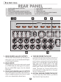
1
SP3 OWNER’S MANUAL IMPORTANT SAFETY INSTRUCTIONS The lightning flash with arrowhead symbol within an equilateral triangle, is intended to alert the user to the presence of un-insulated “dangerous voltage “ within the product’s enclosure that may be of sufficient magnitude to constitute a risk of electric shock to persons. The exclamation point within an equilateral triangle is intended to alert the user to the presence of important operating and maintenance (servicing) instructions in the literature accompanying the product. 1. 2. 3. 4. 5. 6. 7. 8. 9. Read these instructions. Keep these instructions. Heed all warnings. Follow all instructions. Do not use this apparatus near water. Clean only with dry cloth. Do not block any ventilation openings. Install in accordance with the manufacturer’s instructions. Do not install near any heat sources such as radiators, heat registers, stoves, or other apparatus (including amplifiers) that produce heat. Do not defeat the safety purpose of the polarized or grounding-type plug. A polarized plug has two blades with one wider than the other. A grounding type plug has two blades and a third grounding prong. The wide blade or the third prong are provided for your safety. If the provided plug does not fit into your outlet, consult an electrician for replacement of the obsolete outlet. 10. Protect the power cord from being walked on or pinched particularly at plugs, convenience receptacles, and the point where they exit from the apparatus. 11. Only use attachments/accessories specified by the manufacturer. 12. Use only with the cart, stand, tripod, bracket, or table specified by the manufacturer, or sold with the apparatus. When a cart is used use caution when moving the cart/apparatus combination to avoid injury from tip-over. 13. Unplug this apparatus during lightning storms or when unused for long periods of time. 14. Refer all servicing to qualified service personnel. Servicing is required when the apparatus has been damaged in any way, such as power-supply cord or plug is damaged, liquid has been spilled or objects have fallen into the apparatus, the apparatus has been exposed to rain or moisture, does not operate normally, or has been dropped. WARNING: TO REDUCE THE RISK OF FIRE OR ELECTRIC SHOCK, DO NOT EXPOSE THIS APPARATUS TO RAIN OR MOISTURE. DO NOT EXPOSE THIS EQUIPMENT TO DRIPPING OR SPLASHING AND ENSURE THAT NO OBJECTS FILLED WITH LIQUIDS, SUCH AS VASES, ARE PLACED ON THE EQUIPMENT. TO COMPLETELY DISCONNECT THIS EQUIPMENT FROM THE AC MAINS, DISCONNECT THE POWER SUPPLY CORD PLUG FROM THE AC RECEPTACLE. THE MAINS PLUG OF THE POWER SUPPLY CORD SHALL REMAIN READILY OPERABLE. BRYSTON LIMITED WARRANTY Bryston analog audio products are warranted to be free from manufacturing defects for twenty (20) years from the original date of manufacture. The warranty includes parts and labour. Bryston Digital products and cables are warranted for five years from the original date of manufacture. The warranty includes parts and labour. Bryston products having motorized moving parts, excluding motorized volume controls, are warranted for three years from the original date of manufacture. The warranty includes parts and labour. Bryston will remedy the problem by repair or replacement, as we deem necessary, to restore the product to full performance. Bryston will pay shipping costs one way (usually the return portion) during the first three years of warranty coverage. In the event of a defect or malfunction, contact Bryston’s repair centres for return authorization. Products must be returned using original packaging material only. Packing material may be purchased from Bryston if necessary. This warranty is considered void if the defect, malfunction or failure of the product or any component part was caused by damage (not resulting from a defect or malfunction) or abuse while in the possession of the customer. Tampering by persons other than factory authorized service personnel or failure to fully comply with Bryston operating instructions voids the warranty. This warranty gives you specific legal rights and you may also have other rights which may vary from province to province and country to country. As of 2006-02-22 Bryston will only warranty Bryston products purchased through authorized Bryston dealers. Bryston products with a date code of 0608 or higher (date code format is “yyww”, where “yy” is the two least significant digits of the year and “ww” is the week of the year) must be accompanied by a copy of the bill-ofsale from a Bryston authorized dealer to qualify for warranty service. The warranty is transferable from the original owner to a subsequent owner as long as a copy of the bill-of-sale from the original authorized Bryston dealer accompanies the re-sale. The copy of the bill of sale to any subsequent owner need ONLY include the Name of the Bryston Authorized Dealer and the Model and Serial number of the Bryston product The warranty will only be honored in the country of the original purchase unless otherwise pre-authorized by Bryston. BRYSTON SERVICE in CANADA: Postal address: Courier address: P.O. BOX 2170, Stn. Main PETERBOROUGH, ONTARIO CANADA K9J 7Y4 677 NEAL DRIVE PETERBOROUGH, ONTARIO CANADA K9J 6X7 PHONE:705-742-5325 FAX:705-742-0882 E-mail:[email protected] BRYSTON SERVICE in the USA: BRYSTON SERVICE outside Canada and the USA: 79 COVENTRY ST., Suite 5 NEWPORT, VERMONT U.S.A. 05855-2100 contact your local distributor or PHONE:802-334-1201 FAX: 802-334-6658 E-mail:[email protected] CHECK OUR WEB SITE: E-MAIL BRYSTON DIRECTLY: FAX BRYSTON DIRECTLY: PHONE BRYSTON DIRECTLY: www.bryston.com [email protected] 01-705-742-0882 01-705-742-5325 SP3 PREAMP / PROCESSOR TABLE OF CONTENTS ■ Safety Instructions & Warranty . . . . . . . . . . . . . . . . opposite page ■ Introduction, Safety, Accessories & Quick Start . . . . . . . . . . . . . 3 ■ FRONT Panel Features Alpha-numeric Display . . . . . . . . . . . . . . . . . . . . . . . . . . 4 Menu Navigation Buttons Functions & Operations Buttons Surround Mode Digital HDMI 2 Channel Bypass Stereo Down-mix . . . . . . . . . . . . . . . . . . . . . . . . . . 5 Volume Control & Rotary Encoder Headphone Jack Main / Zone Select . . . . . . . . . . . . . . . . . . . . . . . . . . 6 Source Select Buttons Standby Button ■ REAR Panel Features Single Ended Analog Outputs . . . . . . . . . . . . . . . . . . . . 7 HDMI Inputs Zone 2 Outputs Tape Loops Single Ended Analog Inputs . . . . . . . . . . . . . . . . . . . . . 8 SPDIF Inputs Data plate and Caution labels Power Inlet RS232 Serial Data Port . . . . . . . . . . . . . . . . . . . . . . . 9 Ethernet Data Port TOSLINK Optical Inputs & Output Remote Trigger Input & Outputs USB 2.0 Type A port Auxiliary Infra-red Hard Wired Input AES/EBU Balanced Digital Audio Inputs Single Ended Analog 7.1 Surround Inputs Balanced Analog Audio Inputs Balanced Analog Audio 7.1 + 2 Surround Outputs ■ FUSES . . . . . . . . . . . . . . . . . . . . . . . . . . . . . . . . . . . 10 ■ INFRA-RED REMOTE CONTROL & CODES . . . . . . . . . . . . . . . 11 ■ MENU TREE . . . . . . . . . . . . . . . . . . . . . . . . . . . . . . . . 12 ■ Menu Tree Notes . . . . . . . . . . . . . . . . . . . . . . . . . . . . 13-14 ■ Specifications & Trademark Acknowledgements . . . . . . . . . . . . 14-15 ■ 5.1 Surround Speaker Placement Guide . . . . . . . . . . . . . . . . . 16 ■ 7.1 Surround Speaker Placement Guide . . . . . . . . . . . . . . . . . 17 ■ Exterior Dimensions . . . . . . . . . . . . . . . . . . . . . . . . . . . . 18 ■ Appendix A: SP3 Surround Modes . . . . . . . . . . . . . . . . . . . . 19 ■ Appendix B: RS232 Codes . . . . . . . . . . . . . . . . . . . . . . . 20-22 ■ Appendix C: RS232 Port Hookup . . . . . . . . . . . . . . . . . . . . . 23 ■ Appendix D: HDMI Handshaking . . . . . . . . . . . . . . . . . . . 24-25 ■ Appendix E: USB Guide . . . . . . . . . . . . . . . . . . . . . . . . 26-27 ■ Appendix F: Web Interface Guide . . . . . . . . . . . . . . . . . . . 28-33 ■ Appendix G: SubWoofer Setup . . . . . . . . . . . . . . . . . . . . . 34-35 ■ Appendix H: Local Area Newtork (LAN) Setup . . . . . . . . . . . . . 36-39 ■ Appendix I: Dolby Volume/DRC Setup . . . . . . . . . . . . . . . . . 40-41 ■ Appendix J: Firmware Update/Upload Instructions . . . . . . . . . . 42-46 INTRODUCTION Congratulations on your purchase of the Bryston SP3 pre-amplifier/processor. This product will provide you with the finest available signal control and DSP audio processing available. Like all Bryston products the SP3 has been carefully designed and engineered to deliver a lifetime of enjoyment. The SP3 offers both pre-amplifier and digital decoding functions, and it is very important that you thoroughly read this manual BEFORE you install and use the SP3. UNPACKING Your SP3 was carefully packed at the factory to protect against any damage in shipping and handling. Carefully examine the packing and the unit for any signs of external damage or impact and report those to your dealer or Bryston prior to using the unit. Bryston advises that you keep all packaging in the event that the unit may have to be returned for service. ACCESSORIES In the carton you should have found the following accessories in addition to the SP3: 1 Bryston SP3 Instruction Manual 1 IEC standard power cord 1 BR3 Infrared Remote Control unit with battery installed SAFETY It is important that you read and completely understand the safety instructions and warning on page one of this manual before installing or connecting the SP3 to any electrical power source. QUICK START • P lug into an appropriate power source using an approved IEC-60320 power cord with a C13 plug on the equipment end. Check the Data Plate (a 1.5” x .625” sticker containing the electrical ratings for your unit) located on the rear panel near the power inlet to confirm that the unit you have is rated for the electric power supply in your region. • Connect suitable inputs & outputs to the SP3. If you are connecting a DVD player to an SPDIF or TOSLINK input, connect it initially to SPDIF-1 or TOSLINK INPUT-1 (which are the default assignments; these assignments can be changed at any time in System Menu Digital Sources). If you are connecting to an HDMI input, use HDMI-1 which is as- signed to the DVD buttons on the front panel and the remote control. The video signals carried on the HDMI cable are looped through to the HDMI outputs. • The Status LED located above the Standby button should be lit red a couple of seconds after the unit is plugged in. Press the Standby button & the red LED will extinguish & the alphanumeric display will come on, initially showing “Bryston Surround Processor 3”. • Within a second or two the status screen will be displayed showing four lines: Source (input source signal), IN: (input format), OUT: (output signal format) and Volume: (in decibels). Before adjusting items in the menus described below it should be noted that the factory default settings should be suitable for most typical surround setups. In short, the factory defaults for the most fundamental settings are: • Speakers: 5.1 (Source Setup, Spkr Sz) • Speaker Size: small (Source Setup) • Subwoofer: On (Source Setup) • Distance: 2 meters (System Setup) • Speaker levels:0 (Source Setup) • P ress the right arrow menu navigation button and you will be at the top of the main menu. When the cursor is pointing at SYSTEM SETUP and you press the right arrow button again you will move into the System Setup menu. However, if you press the down arrow first so that the cursor is pointing at SOURCE SETUP, then pressing the right arrow button will move you into the Source Setup menu. • To back up, all the way to the startup screen if desired, just keep pressing the Left arrow button . For more information on the menu system, see pg 12 Owner’s Manual Updates The SP3 Owner’s Manual is regularly updated. Check the Downloads Technical section of Bryston’s website at www.bryston.com for the latest revisions. Note: the revision number follows the document number, separated by a dash, and can be found in the bottom left corner of the last page of this and other Bryston Owner’s Manuals. SP3 PREAMP / PROCESSOR FRONT PANEL A: B: C: D: ALPHA NUMERIC DISPLAY MENU NAVIGATION Buttons FUNCTION & OPERATION Buttons VOLUME CONTROL A:ALPHA-NUMERIC DISPLAY This is a dot matrix display that can display graphics as well as 4 lines of alpha-numeric characters. The brightness of the display can be set in 4 steps from 25% to 100% using the DISPLAY button (see section “C” below). A default brightness level can also be set in the System Setup menu as can the automatic time-out period (from 30 to 600 seconds). When the timeout period expires the display will extinguish automatically. To reawaken the display press the currently illuminated Source Select button (section “G” below). Pressing any button or turning the rotary encoder (Volume control knob) will also wake up the display but will also effect a change (e.g. rotating the volume control clockwise will increase the volume, etc.). B:MENU NAVIGATION BUTTONS This cluster of 4 buttons are used to navigate the menus on the Alpha-numeric display. After the unit has powered up a status screen is displayed like that at the right. Press the right arrow button () to enter the main menu. Use the left arrow button () to step back up through the menus. The up () and down () buttons are used to move up and down through the menu items. The rotary encoder (volume control) can be used to set most parameters, even on/off choices. The two Surround Mode buttons can also be used to choose from preset value options. Up () and/or down () arrows may be displayed at the right hand side of the display to indicate that more items are listed either above and/or below the current screen. Use the up () and () down buttons to go to these items. See also MENU MAP on page 8 E: HEADPHONE JACK F: OUTPUT SELECT Buttons G:INPUT SELECT Buttons H:STANDBY Button C: FUNCTIONS & OPERATIONS BUTTONS ■DISPLAY Selects display brightness in four steps: 25%, 50%, 75% & 100%. To set an automatic timeout for the display to extinguish, set the options n the SYSTEM SETUP -> MISC. menu. Choosing DISP+LED TOUT instead of DISP TIMEOUT will apply the display timeout value to all front panel indicator LEDs as well as the dot-matrix display. Once a value for DISP+LED TOUT has been set the front panel DISPLAY button will also facilitate extinguishing all LEDs plus the dot-matrix display. ■ SURROUND MODE These Left & right Surround Mode ( & ) buttons allow for selection of up to 8 different surround modes including: PLIIx-Music, PLIIx-Movie , Neo-6 Music, Neo-6 Cinema, PLIIx-Natural, Pro Logic, Club , Party, Stereo-7. These modes derive surround modes from stereo (2 channel) analog DVD inputs. If a 5.1 surround signal is selected as the input, some surround modes can derive the 7.1 format Back channels from the left and right surround channels. These buttons can also be used to select values in the menu system. See Appendix for more information about the various surround modes. ■DIGITAL Sets the source select button (G) to select from 1 of the 4 SPDIF inputs (RCA [phono] jacks, one of two AES ■HDMI Sets the source select buttons (G) to select one of 8 HDMI inputs. The audio content will be processed through the SP3’s DSP but the video content will simply be passed through to the two (parallel) HDMI outputs. ■ 2 CHANNEL BYPASS Selects Left and right (or the front left and right) inputs from whatever analog source is currently selected. If the DIGITAL mode is active (i.e. if the LED above the DIGITAL button is ON) then this becomes a digital down-mix into a stereo Left and Right output. ■STEREO & STEREO DOWN-MIX MODE If this button is selected and the supplied bitstream is more than 2 channels, the decoder will automatically implement a stereo down-mix. Otherwise, analog or digital two channel signals are passed as conventional stereo. NOTE: Down-mix is a software based automatic mixing function available within the SP3. This process exists because whenever the number of active decoder outputs or loudspeakers selected in setup is less than the number of channels in the Dolby Digital program, some channel combining will be neces sary to present the program on the available number of channels/loudspeakers. As a part of any program’s production, its producers can set and adjust the type and ratios allowed for down-mixing somewhat to ensure optimum results without compromising the full Multichannel balance. This is accomplished by including specific data within the Dolby Digital bitstream which represents different mixing coefficients for the centre and surround channel signals. These will be detected by the SP3 and used to produce the down-mix if this mode is selected. D: VOLUME CONTROL / ROTARY ENCODER Continuous rotary optical encoder for determining volume level as well as an input for most variable settings and other selections within both the System and Source menus. Note that when the volume level is being adjusted the display changes to large numerals showing the level in decibels SP3 PREAMP / PROCESSOR E: HEADPHONE JACK Stereo (3 conductor) 1/4” headphone jack. In 2 Channel Bypass mode the Left and Right analog inputs appear, amplified, at the headphone jack. When other sources are selected a stereo down-mix is used. F: MAIN / ZONE SELECT above HDMI button is ON) the first 8 source select buttons (DVD, CBL/SAT, TUNER, CD, DVR, TAPE, BAL-1, BAL-2) represent HDMI inputs 1 through 8 respectively. When MAIN is selected, source signal selected will appear at the MAIN outputs. When ZONE is selected, the source signal selected will appear at the ZONE 2 OUT outputs The SP3 can send a different stereo audio source H:STANDBY BUTTON signal to its ZONE outputs (Zone 2 Out) than to its Places the unit in standby mode. Status indicator LED is normally off when unit is operating. It turns main outputs (Single Ended Outputs or Balanced red when unit is placed in standby mode. When Outputs). Pressing the MAIN button allows selecuploading new software it may blink off and on in tion of the signal that will go to the Single Ended different colours. The specifics of theses different Outputs and Balanced Outputs using the source colour states is significant only to engineering and select buttons (item “G”) while pressing ZONE service personel. allows the same source select buttons to set the Power consumption in Standby mode is <1 Watt. signals that will be sent to the Zone 2 Out outputs) G:SOURCE (INPUT) SELECT BUTTONS Ten buttons for selecting audio input source signals (see ”F” above). When HDMI is selected (LED REAR PANEL 1: SINGLE ENDED ANALOG OUTPUTS 2: 3: 4: 5: HDMI INPUTS ZONE-2, SINGLE ENDED, ANALOG OUTPUTS 1st ANALOG TAPE LOOP IN/OUT CONNECTORS 2nd ANALOG TAPE LOOP IN/OUT CONNECTORS 1: SINGLE ENDED ANALOG OUTPUTS The SP3 offers both balanced (3 pin XLR male connectors [pin 2+, pin 3-] and unbalanced (RCA/phono jacks) output connectors. 2: HDMI INPUTS Although the SP3 uses only the audio signals carried on an HDMI cable, the video signals are routed to the two parallel HDMI outputs from the selected HDMI input. 3:ZONE 2 SINGLE ENDED ANALOG OUTPUTS A pair of RCA jacks that provide a second stereo signal path completely separate from the main output with its own independently selected inputs 6: SINGLE ENDED ANALOG INPUTS 7: SPDIF INPUTS 8: DATA PLATE LABEL 9: CAUTION, RECYCLING & OTHER SYMBOLS 10: IEC-320 C14 POWER INLET 4: TAPE RECORDER TAPE LOOP A conventional tape loop consisting of two pairs of RCA jacks; one stereo pair of inputs and one stereo pair of outputs. A stereo down-mix for the selected source (or, in 2 Channel Bypass mode, the Left and Right analog inputs directly) appear at the TAPE OUTPUTS, unless the selected source is the TAPE INPUT itself in which case the TAPE OUTPUTS are muted. The inputs can, of course, also be used as just another pair of analog inputs, but at unity gain only & no volume control. 5: DIGITAL VIDEO RECORDER TAPE LOOP A second tape loop which functions just like the Tape Recorder Tape Loop above. SP3 PREAMP / PROCESSOR 11: 12: 13: 14: 15: RS232 SERIAL PORT (DB9) ETHERNET PORT (RJ45) TOSLINK OPTICAL IN/OUT CONNECTORS TRIGGER INPUT/OUTPUT CONNECTORS USB PORT (USB 2.0 type B) 16: 17: 18: 19: 20: 6:SINGLE ENDED ANALOG INPUTS Four pairs of general purpose analog inputs labelled CD, TUNER, CABLE/SAT, & DVD. Input voltage should limited to less than or equal to 5VRMS addition. In stereo bypass mode the input voltage should be limited to ≤ 8VRMS 7: DIGITAL AUDIO COAXIAL INPUTS The TV/SAT, DVD, CD, and AUX front panel selectable sources are also supplied with a standard SPDIF gold RCA jack digital audio input. These four inputs will accept any standard SPDIF source including DAT, CDR and similar components. AUXILIARY INFRA-RED HARD WIRED INPUT AES/EBU DIGITAL INPUTS (3 pin XLR female) SINDLE ENDED 7.1 ANALOG SURROUND INPUTS BALANCED ANALOG INPUTS (3 pin XLR female) BALANCED 7.1 + 2 ANALOG OUTPUTS (XLR male) 8:DATA PLATE Model name, electrical rating, date code (when manufactured), serial number & revision number. 9: CAUTION LABEL Risk of shock electric shock ~ do not open. Refer servicing to qualified personel. Note, however, that the SP3 does contain two 5x20mm glass fuses on the upper deck power supply board. Refer to FUSES sections on the next page for more information. 10:IEC-320 C14 POWER INLET Mates with C13 power cord connector. Determine the correct operating voltage from the DATA PLATE and connect to an appropriate power source using an approved power cord. 11:RS232 SERIAL PORT (DB9) Serial data port utilizing a DB9 female connector. For connection to system control systems such as Crestron and AMX. also Refer to the Menu Tree on page 14 15:USB 2.0 TYPE A INPUT Used as a digital audio input an as a control input for certain audio control systems. 12:ETHERNET PORT (RJ45) For interconnections to personal computers (and/or 16:AUXILIARY INFRA-RED INPUT routers) to facilitate SP3 software updates and also for control functions through audio system controls (Crestron, AMX, etc.) and computer control applications. This acts an an HTTP serve. See Appendix H for more r 13:TOSLINK DIGITAL AUDIO OPTICAL INPUTS A 3mm two conductor phone jack which will accept a hardwired DC voltage that is the electrical equivalent of the optical signal generated by an infrared emitter in a remote control. This will primarily used as by infra-red remote control extenders. The tip is positive, the sleeve is negative and the signal level should be 5vdc max. (Positive or “1”) and 0v or ground (negative or “0”) The SP3 offers two assignable TOSLINK optical inputs. These can be designated to any input using the OS menu (“Other Settings”)on the LCD screen. 17:AES/EBU BALANCED DIGITAL INPUT Please note that if you choose to assign an optical Two 3 pin female XLR jacks for digital audio inputs input to an input with a coaxial input, the coaxial will conforming to the Audio Engineering Society/Eube over-ridden and the optical input signal will be ropean Broadcasting Union standard formalized used by the SP3. as the IEC 60958 standard using 110 Ohm shielded The pro model replaces the two TOSLINK connectwisted pair wire. tors with a single AES/EBU Digital connector. 14:TRIGGER INPUTS & OUTPUT 18: SINGLE ENDED (UNBALANCED) 7.1 SURROUND SOUND INPUTS Four 3mm two-conducter phone jacks with the tip Eight RCA jacks for connecting single-ended analog being positive and the sleeve being negative. A surround signals to the SP3; Front-Left, Front-Right, voltage of between 3 and 12V on the trigger input Front-Centre, Left Surround, Right-Surround, Backwill turn the SP3 on. Removing the trigger voltage Left, Back-Right & Sub-woofer. will cause the SP3 to turn off. The input voltage can be of either polarity, that is, the phone plug tip can 19:BALANCED ANALOG INPUTS be positive and the sleeve negative, or visa versa Four XLR female jacks (2 left/right pairs) referred to as Balanced Input #1 and Balanced Input #2. These inputs conform to the EIA RS-297 standard wherein pin #1 is ground (chassis & shield), pin #2 is positive and pin #3 is negative. 20:BALANCED ANALOG AUDIO 7.1 + 2 SURROUND SOUND OUTPUTS The three outputs can be programmed to go either high (+12Vdc, ±0.6V) or low (gnd) when specified inputs are selected. These assignments are found in the SOURCE menu (SOURCE TRIGGERS). A delay can also be specified (in the SYSTEM MISC TRIGDELAY menu) to delay the time when the trigger output goes to the chosen state (high or low) after an assigned input has been selected. See Ten 3-pin XLR male connectors conforming to the EIA RS-297 pinout (pin #1 = ground, pin #2 = positive and pin #3 = negative). In addition to the usual eight 7.1 outputs (Front-Left, Front-Centre, FrontRight, Surround-Left, Surround-Right, SurroundRear-Left, Surround-Rear-Right and SubWoofer) there are two Auxiliary outputs (L-Aux and R-Aux). The signals present on these outputs can be programmed in the SYSTEM MISC AUX menu. The two options are: Stereo L+R : This puts a stereo down-mix signal on the two AUX output jacks, the same stereo down-mix that appears on the headphone jack. Centre & Sub: This options puts the Centre channel onto the L-AUX connector and SP3 PREAMP / PROCESSOR the SUB channel onto the R-AUX connector thus facilitating the use of two sub-woofers and/or two centre channel speakers. See the illustration “Suggested Surround Speaker Placement” on page 18 FUSES There are two 5x20mm glass fuses located on the upper deck power supply board as shown below. One fuse is for the standby power supply and the other is for the main power supply transformer. The values for these two fuses are as follows: 120Vac models 220-240Vac models Stand-by fuse (F2): F 500mA 250V F 500mA 250V Part numbers: Littelfuse 217.500 Littelfuse 217.500 Main PSU fuse (F1):F 1.6A 250V T 1A 250V Part numbers: Littelfuse 217 01.6 Littelfuse 218 001 Before attempting to change fuses, disconnect all cables from the SP3, especially the power cord. Then remove all the screws from the top and left & right sides that hold the top cover in place. Remove the top cover by sliding towards the back of the unit and then lifting up. Be sure to replace all screws when replacing the top cover using no more that 16 inch-pounds of torque. When removing screws from top cover use only the proper driver, a Torx #8, and do not use excessive force as it may damage the screw head. If the screw does not move tap lightly with a hammer to loosen the threads. If this doesn’t work, please refer the unit to qualified service personel. F2: STANDBY FUSE For both 120Vac & 230Vac models: F 500mA 250V 220-240Vac models: T 1A 250V (Littelfuse 217.500) (Littelfuse 218 001) F1: MAIN FUSE 120Vac models: F 1.6A 250V (Littelfuse 217 01.6) IR REMOTE CONTROL The SP3 Remote Control can operate all front panel operations in addition to having a MUTE button to for quickly silencing the output of the SP3. Several other functions are accessible by sending 3 digit numeric codes to the SP3. To send codes to the SP3: 1:Press and hold the CODE button until the status LED on the remote (located between the CODE and POWER buttons) flashes a couple of times & then stays lit steadily red; then release 2: Within a few seconds, while the status LED remains steadily lit, enter the desired 3 digit numeric code (see the table below for valid codes). Refer to the Function Power Off (Standby) Source TV/SAT Source DVD Source CD Source TUNER Source DVR Source TAPE Volume Up Volume Down Mute Main or Zone tog Pink Noise Test Digital toggle Dolby EX Force/Auto Stereo toggle Zone/Zmute toggle Power/Standby toggle DTS ES Force/Auto Surround On Surr Right arrow/Mode Menu Up arrow Menu Down arrow Select button Centre Speaker Rear Speaker Back Speaker Subwoofer Speaker Save Config 2-Ch Bypass toggle Source 7 .1 Bypass Power On n/a OSD On/Off OSD Off OSD On MONO On 2-Ch Bypass On Source 7 .1 Bypass 2-Ch Bypass Off Digital On Digital Off Mute Main or Zone On Mute Main or Zone Off Rev . 701-01 Code 0 1 2 3 4 5 6 7 8 9 10 11 12 13 14 15 16 17 18 19 20 21 22 23 24 25 26 27 28 29 30-48 49 50 51 52 53 54 55 56 57 58 59 Function Sub in Bypass toggle SurrEff2 None SurrEff2 Pro-Logic SurrEff2 NonePLII Music SurrEff2 PLII Movie SurrEff2 Neo-6 Music SurrEff2 Neo-6 Movie SurrEff2 Stereo 7 SurrEff Party SurrEff2 Hall SurrEff2 Church SurrEff2 Stadium SurrEff Club SurrEff2 Theatre SurrEff2 Natural SurrEff7 DD 5 .1 SurrEff7 DD EX Movie6 SurrEff7 PLIIx Music6 SurrEff7 PLIIx Movie7 SurrEff7 PLIIx Music7 SurrEff7 PLIIx AUTO SurrEff2 Stereo7x HDMI toggle Source BAL1 Source BAL2 Source USB Main/Mmute toggle n/a Surr Left arrow Surr Right arrow Menu Left arrow Menu Right arrow n/a HiddenMenuUnlock n/a Reserved Reserved DISPLAY toggle n/a TEST LEDs & DISP n/a System RST&REBOOT Stan B. 15-Feb-2012 BR3 illustration below for the location of the number keys on the remote. 3: When a valid code has been entered the LED will flash twice to confirm that the code has been accepted. Certain features in the remote control itself can also be programmed by entering codes as described above. The only differece is that these codes affect only the BR3 remote control itself and are not sent to the SP3. These codes are as follows: 792: Toggle motion sensor on/off (backlight control) 797: Toggle backlight on/off Code 60 64 65 66 67 68 69 70 71 72 73 74 75 76 77 78 79 80 81 82 83 84 85 86 87 88 89 90-93 94 95 96 97 98-221 222 223-237 238 239 240 241-244 245 246-254 255 BACKLIGHT OPERATION When enabled, the backlight will only come on when the ambient light falls below a predetermined level. If the motion detector (code 792) is disabled then the backlight will come on only when a button is pressed AND the ambient light level is low enough. If both the backlight and the motion detector are both enabled the backlight will come on when the unit experiences movement and/or when any of the buttons are pressed AND the ambient light is low enough. SP3 PREAMP / PROCESSOR SYSTEM SETUP MENU TREE SPEAKER DISTANCES DIGITAL SOURCES MISCELLANEOUS SOURCE SETUP L (left) C (centre) R (right) Rs (right surround) Rb (right back) Lb (left back) Ls (left surround) SUB (sub-woofer) 09.0m, 09.0m, 09.0m, 09.0m, 09.0m, 09.0m, 09.0m, 09.0m, 0355 0355 0355 0355 0355 0355 0355 0355 DVD SAT TUNER CD DVR TAPE SPDIF SPDIF SPDIF SPDIF SPDIF SPDIF BRIGHTNESS (of display) HEADPHONES PRESET VOLUME AUX OUTPUTS AUTO SAVE DISPLAY TIMEOUT SPEAKER DISTANCE UNITS TIGGER DELAY DHCP IP address (read only) IP mask 25%, 50%, 75%, 100% -12 dB +6 dB -60 dB +10 dB Stereo L+R, Center & SubWoofer ON, OFF 2, 10, 30, 120 minutes meters, feet, inches, milli-seconds 0, 5, 10, 15, 20, 25, 30 seconds 14, 14, 14, 14, 14, 14, in., in., in., in., in., in., in., in., OPTO OPTO OPTO OPTO OPTO OPTO 030 030 030 030 030 030 030 030 ft., ft., ft., ft., ft., ft., ft., ft., 026msec. 026msec. 026msec. 026msec. 026msec. 026msec. 026msec. 026msec. 13 13 13 13 13 13 Server, Client & Server, Static IP, Client, Auto IP 255.0.0.0 255.255.255.192 TESTS PINK NOISE AUTOCYCLE, MANUAL SPEAKER SIZE FRONT CENTER SURROUND BACK Large, Large, Large, Large, Small Small, None Small, None Small, None, 1 Sm, 2 Sm, 1 Lrg, 2 Lrg L C R Rs Rb Lb Ls SUB -12 -12 -12 -12 -12 -12 -12 -12 SPEAKER LEVEL (left) (centre) (right) (right surround) (right back) (left back) (left surround) (sub-woofer) dB dB dB dB dB dB dB dB dB dB dB dB dB dB dB dB CROSSOVER FRONT CENTER SURROUND BACK 40 40 40 40 SUBWOOFER SUB WOOFER in2Bypass XTRA BASS ON. OFF ON, OFF ON, OFF (for Lrg front spkrs), DISABLE (for sm front spkrs) TRIGGERS TRIGGER #1 TRIGGER #2 TRIGGER #3 ON, OFF ON, OFF ON, OFF DTS ES APPLY Neo:6 Center FORCE, AUTO 0 1.0 (0.3 = default) DOLBY PLII Music Pan (Panaramic) PLII Music Cen (Centre) PLII Music Dim (Dimension) EX apply ON, OFF 0 (C max), 1, 2, 3 (L,C,R), 4, 5, 6, 7 (no ctr) 4 (back), 5, 6, 7 (neutral), 8, 9, 10 (front) FORCE, AUTO OTHER HDMI OUT DIGI OUT LIPSYNC PCM ZR (zero run) Loop through, Down mix ZoneDAC, TOSLINK 0 255 mSec Full, Gapless, Disable, Auto, Default2 200 200 200 200 +12 +12 +12 +12 +12 +12 +12 +12 Hz. Hz. Hz. Hz. MENU TREE NOTES SYSTEM SETUP MENU: SPEAKER DISTANCES: Units for speaker distances are set in the SYSTEM > MISC. menu. Speaker distances are measured as radii from the listeners position. See the illustration SUGGESTED SURROUND SPEAKER PLACEMENT on page 18. DIGITAL SOURCES: Each of the Source Select buttons, on the front panel and on the remote control (DVD, CBL/SAT, TUNER, etc) can be programmed to select a digital input from one of the four co-axial SPDIF inputs or one of the 3 TOSLINK optical inputs. . AUTOSAVE: When enabled (ON) settings are saved whenever you backup through the menu by pressing the left arrow button (). If Autosave is OFF settings will NOT be saved unless teh SAVE button is pressed on the remote control. TRIGGER DELAY: The SP3 can be set to produce a 12Vdc trigger signals on any of the three Trigger Output jacks. See item 14 on page 9 (TRIGGER INPUTS & OUTPUTS). The tip of the two conductor (3mm) phone jack is positive and the sleeve is ground (0v). TESTS (Pink Noise): Will put a burst of pink noise, sequentially, on all speakers while displaying which output the test signal is being sent to. This is intended to help you verify that the connections and speaker levels are correct. Within the MISCELLANEOUS: System Setup Test menu, move the cursor to select HEADPHONES: PINK NOISE and press the right arrow button () to The signal level at the headphone jack can be initiate the test (and the left arrow button () to stop it, adjusted from -12 dB to +6 dB to match head- if desired). The auto-cycling will stop on its own once phone level more closely to the speaker listening all outputs have been sent a pink noise burst. To operlevels ate the pink noise test manually from the front panel, press the right arrow button again each time you wish PRESET VOLUME: to advance through the outputs, sequentially putting The volume level at power-up can be pre-set to pink noise bursts on one speaker after another. In this anywhere between -60 and +30dB case the noise test switches to “manual” mode and each channel will play until the right or left arrow is pressed AUX Outputs: again. Pressing the left arrow button will exit the test The L-AUX and R-AUX auxilliary output jacks sequence. (XLR -male balanced) can be set, by this menu To use the BR3 remote control to initiate the test item, to be either another Left/Right stereo pair press the TEST button on the remote . To change form of outputs or another sub-woofer and another AUTOCYCLE to MANUAL press the TEST button again centre channel surround outputs. To advance the channel from the remote press right As a stereo pair, the signal is analog if the SP3 is arrow again; to exit press left arrow button. in 2 CHANNEL BYPASS mode or otherwise it is a The volume control can be used to adjust the outdigital downmix from multi-channel inputs. put levels during the test. As set to provide another sub-woofer and centre channel output, the signals for these channels are SOURCE SETUP MENU: the same as the signal that would be present on SPEAKER SIZE: the main Sub-woofer and Centre channel outputs Large speakers are assumed to be able to handle all connectors. These simply provide a convenient frequencies down to at least 40 Hz. A speaker defined way of using two centre channel speakers and/or as SMALL has the low frequencies filtered out. The two sub-woofer speakers. default crossover point for the low frequencies is 80 Hz but this can be changed in software (SOURCE SETUP SP3 PREAMP / PROCESSOR MENU TREE NOTES continued: > CROSSOVER) from 40 to 200 Hz. The speaker size menu also allows for turning the CENTRE, SURROUND & BACK speakers off by selecting NONE. Also, the BACK speaker setting allows for choosing from one or two back speakers. By turning the BACK speakers off, the surround sound speaker configuration becomes “5.1”. By choosing only 1 BACK speaker the configuration becomes “6.1”. SPECIFICATIONS PERFORMANCE SPECIFICATIONS A/D Conversion: D/A Conversion: DSP Engine: Power Supply: 24-Bit, 192 kHz Delta-Sigma 24-Bit, up to 192 kHz Delta-Sigma TI DA710 Separate off-line standby PSU plus & main linear power supply with toroidal power transformer utilizing multiple regulation stages. Frequency Response: 20 Hz to 20 kHz +/- 0.25 dB Low Frequency Cutoff: 0.3 Hz (all speakers channels in Bypass mode) 1.8 Hz (LARGE Speakers and SubWoofer in Analog, Digital or HDMI) 40-200 Hz(variable cutoff point; default 80 Hz) SMALL speakers, except SubWoofer, in Analog, Digital or HDMI) High Frequency Cutoff: 40-200 Hz(variable cutoff point; default 80 Hz) (SubWoofer in Analog, Digital or HDMI) 22 kHz (all speakers, except SubWoofer, in Analog, Digital or HDMI) 180 kHz(all speaker channels in BYPASS) THD+Noise:< 0 .006% in DSP modes; < 0.0025% in Bypass mode 20Hz to 20kHz at maximum output level. Signal-to-Noise Ratio:105dB in DSP Modes; 110dB in 2ch Bypass Mode; 22 kHz bandwidth, Ref. 1 kHz at max. output Input Level: 2 Vrms in DSP modes; 4 Vrms in Bypass Mode Input Impedance: 50 kOhms for single-ended analog audio, 1K Ohms for balanced analog inputs Output Level: 8 Vrms (16 Vrms Balanced) in DSP Modes; 10 Vrms (20 Vrms Balanced) in Bypass Mode. Output Impedance: 110 Ohms Bass Management: 2nd Order HP filter(x5), 4th Order LP filter 40 – 200 Hz Crossover Freq. ELECTRICAL SPECIFICATIONS: Power: INPUTS Analog Audio: 20VAC & 230VAC models. 1 Maximum power consumption: 60 Watts Standby power consumption: <1Watt 4x stereo single ended/unbalanced pairs (CD, Tuner, Cable/Sat, DVD) 2x pairs single ended, unbalanced tape inputs (RCA) 2x pairs of Balanced XLR (female) inputs Digital Audio: 4x coaxial (RCA) 75 Ohms (SPDIF), 3x Optical (TOSLINK) 2x AES/EBU inputs (XLR) 110 Ohms 1x USB 2.0 type B OUTPUTS Analog Outputs: 10 balanced XLR male: Left, Centre, Right, Left Surround, Right Surround, Left Back, Right Back, Left Auxiliary, Right Auxiliary and Subwoofer 16 sindle ended (unbalanced) RCA: Left, Centre, Right, Left Surround, Right Surround, Left Back, Right Back, Left Auxiliary, Right Auxiliary & Subwoofer, 4 tape outputs, 2 Zone Two outputs. Digital Outputs: 2x HDMI 1x TOSLINK optical Trigger Inputs/Outputs: One 12V input and 3 programmable trigger outputs DATA & CONTROL PORTS: 1x Infra-Red sensor; remote control receiver 1x mini (3mm) phone jack (2 conductor) for auxilliary infra-red control data input 1x Ethernet (RJ45 connector): bilateral data, software download, etc. INFRA-RED REMOTE CONTROL Number of buttons: 30 Power Source: two AAA batteries IR Wavelength: 940nm PHYSICAL SPECIFICATIONS Dimensions: Weight: Chassis Temp: 7”W x 14.25”D (not including knobs & connectors) x 5.75”H (not including rubber feet) 1 17”W x 15.38”D (including knobs & connectors) x 6.25”H (including rubber feet) Also available with 19”W dress panels (all other dimensions are the same) approx 22 lbs (10 kg) 50 deg Celsius max. Specifications subject to change without notice. TRADEMARK ACKNOWLEDGEMENTS SP3 PREAMP / PROCESSOR 5.1 SURROUND SPEAKER PLACEMENT GUIDE If the AUX output option is set as Center & Sub then a 2nd Center output is available allowing for two Center channel speakers to be used. Placement will be critical due to the largely voice band signals in this channel. If the AUX output option is set as Center & Sub then a 2nd sub-woofer output is available. It’s placement may not be critical due to the inherent lack of directionality of very low frequencies 7.1 SURROUND SPEAKER PLACEMENT GUIDE SP3 PREAMP / PROCESSOR SP3 EXTERIOR DIMENSIONS APPENDIX A SP3 SURROUND MODES Pressing the SURROUND left () and right ()arrow buttons button will allow you to sequentially select one of the many available decoding modes for expand almost any 2 channel music source signals. The custom SP3 Surround Modes use a set of DSP algorithms to create a set of simulated surround sound signals from the original left and right 2 channel data. CLUB: This Sound Field Mode is intended to simulate being fairly close, around 10 feet away, in a small intimate club setting with a moderate amount of reverberation that does not destroy clarity. The result is a bit colored for speech due to the small room size, but it is quite suitable for jazz groups, cabaret, small-venue rock ‘n roll, and a small disco venue where dance music is played. This mode can also be used for classical chamber music and solo instrumental music of most kinds. NATURAL: PLII Natural mode enhances the basic stereo reproduction by using the inherent acoustics recorded within the source material. If the source material was surround encoded or recorded in an acoustically oriented manner (such as a lot of classical music and many live recordings) this mode can provide truly spectacular effects and an enhanced sense of the space in which the music was being performed. PARTY: The Party (Seven-Channel Mono) Mode converts stereo input to a mono signal which is then distributed to the 7 satellite channels plus sub-woofer. STEREO7: The Stereo7 (Seven-Channel Stereo) Mode converts stereo input to surround sound. The stereo signal is distributed to the 7 satellite channels plus subwoofer, creating a giant stereo image in your listening space. PRO LOGIC: Dolby Surround/Pro Logic is based on basic matrix technology. When a Dolby Surround soundtrack is created, four channels of sound are matrix-encoded into an ordinary stereo (two channel) sound track. The centre channel is encoded by placing it equally in the left and right channels; the rear channel is encoded using phase shift techniques. A Pro Logic decoder/processor “unfolds” the sound into SP3 SURROUND SOUND MODES the original 4.0 surround—left and right, centre, and a single limited frequency-range mono rear channel using ‘Steering Logic’, which drives amplifiers, to raise or lower the output volume of each channel based on the current dominant sound direction. In addition the surround channel is slightly delayed, so that any front channel sounds that leak into the surround channel arrive at the listener after the front channels, providing an illusion of greater separation. PLII MUSIC: This mode can enhance normal stereo music recordings, offering a wider soundstage and enhanced spatial effects. This offers user control over: PLII MOVIE: This is the preferred decoding method for watching movies with matrix surround encoding. The centre width and dimension variables are set and optimized for this application, and cannot be adjusted. No filters are present on the surround channels, and auto-balance is operational. NEO:6 MUSIC: Neo:6 derives a centre channel from two-channel material. Neo:6 music mode to expands stereo non-matrix recordings into the five- or six-channel layout, in a way which does not diminish the subtlety and integrity of the original stereo recording. In music mode, the intent in the front channels is less one of steering and more one of stabilizing the front image by augmenting it with a centre channel, while preserving the original perspective of the stereo mix. Therefore the derived centre is never fully subtracted from the left and right channels. NEO:6 CINEMA: In cinema mode, for Left/Right film soundtracks, sounds steered to the centre are subtracted from the left and right channels. Neo 6 provides up to six full-band channels of matrix decoding from stereo matrix material. Users with 6.1 and 5.1 systems will derive six and five separate channels respectively, corresponding to the standard home-theater speaker layouts. (The “.1” subwoofer channel is generated by bass management in the preamp or receiver.) (Please note that the apparent effect of the Surround Modes can be adjusted by altering the delay parameters and channel volume of the centre, surrounds and back channel(s), using the appropriate menus). SP3 PREAMP / PROCESSOR APPENDIX B SP3 BRYSTON SERIAL PROTOCOL HELP FILE Rel. 5, 21-Dec-2011 SP3 receives commands and send responses to each command. It can optionally broadcast automatic responses to certain system events such as source switching by the front panel etc. (see AUFB). The format of the automatic responses is the same as the response to a serial command sent with the parameter bytes P1 P2 = "QS". Command format are all ASCII strings with the carriage return ending: # D1 D2 C1 C2 C3 C4 P1 P2 ... <CR> # D1 D2 - command start character - device category, 1 digit 1..f(SP3=1) - RS485 device ID, 1 digit 0..f(dflt=0) (D2 can only be changed through the front panel menu!) Currently D1 D2 must be "10".(*) C1..C4 - command name (4 chars) P1,P2,.. - parameters n>=2 chars (variable) <CR> - end character (code 13 or '\r' in C/C++) Example: #10MPWR01<CR> NOTE: ANY CHARACTERS PRECEEDING # AND FOLLOWING THE <CR> WILL BE IGNORED BY SP3. DO NOT INSERT #, SPACES, <LF>, <TAB> OR OTHER NON-PRINTABLE CHARACTERS INSIDE THE COMMAND. Response format is the same as commands, repeating the D,C and P bytes (P bytes may carry the actual status or ?? as error marker) Example: #10MSRC00<CR> NOTE: DO NOT ASSUME THAT THE NUMBER OF RESPONSE BYTES R1,R2.. IS ALWAYS FIXED. ALLOW UP TO 320 CHARS AND READ ALL UNTIL <CR> AT THE END. NAME |PAR |DESCRIPTION |RESPONSE ------|----|------------------|--------MPWR Set Main Power MPWRxx 00 Off (Standby) 01 On QS Query Status MSRC Set Main Source 00 DVD MSRCxx 01 02 03 04 05 06 07 08 09 QS RS232 SERIAL CODES SAT TUNER CD DVR TAPE BAL1 BAL2 USB 7.1 Bypass Query Status 01..99 = inside a sub-menu (see enum MenuState_t) TRIG MVOL Set Main Volume MVOLxxxx UP Up 1 step (0.5dB) DN Down 1 step (0.5dB) xxxx = 0200..1120 in 0.1dB units plus 1000 (-80.0..12.0dB, resolution 0.5dB) QS Query Status MMUT 00 01 02 QS Set Main Mute Mute Off Mute On Mute toggle Query Status MMUTxx ZSRC 00 01 02 03 04 05 08 QS Set Zone Source DVD SAT TUNER CD DVR TAPE Digital Downmix Query Status ZSRCxx ZVOL Set Zone Volume ZVOLxxxx UP Up 1 step (0.5dB) DN Down 1 step (0.5dB) xxxx = 0200..1120 (-80.0..12.0dB) QS Query Status ZMUT 00 01 02 QS Set Zone Mute Mute Off Mute On Mute toggle Query Status ZMUTxx MENU LE RI UP DN SL EX Menu MENUxx Left Right Up Down Select Exit one menu out, or go from Zone to Main QS Query status 00 = in the top (idle) screen Trigger Output TRIGxxx xxx TR1/TR2/TR3 000 All triggers Off 0 Trigger Off 1 Trigger On * Trigger No Change QS Query Status LFVL Left Front Vol Trim LFVLxxxx UP Up 1 step (0.5dB) DN Down 1 step (0.5dB) xxxx = 0880..1120 (-12.0..12.0dB) QS Query Status RFVL Right Front Vol Trim RFVLxxxx UP Up 1 step (0.5dB) DN Down 1 step (0.5dB) xxxx = 0880..1120 (-12.0..12.0dB) QS Query Status CNVL Centre Vol Trim CNVLxxxx UP Up 1 step (0.5dB) DN Down 1 step (0.5dB) xxxx = 0880..1120 (-12.0..12.0dB) QS Query Status SBVL Subwoofer Vol Trim SBVLxxxx UP Up 1 step (0.5dB) DN Down 1 step (0.5dB) xxxx = 0880..1120 (-12.0..12.0dB) QS Query Status LSVL Left Surr Vol Trim LSVLxxxx UP Up 1 step (0.5dB) DN Down 1 step (0.5dB) xxxx = 0880..1120 (-12.0..12.0dB) QS Query Status RSVL Right Surr Vol Trim RSVLxxxx UP Up 1 step (0.5dB) DN Down 1 step (0.5dB) xxxx = 0880..1120 (-12.0..12.0dB) QS Query Status LBVL Left Back Vol Trim LBVLxxxx UP Up 1 step (0.5dB) DN Down 1 step (0.5dB) xxxx = 0880..1120 (-12.0..12.0dB) QS Query Status APPENDIX B: RS232 SERIAL CODES continued RBVL Right Back Vol Trim RBVLxxxx UP Up 1 step (0.5dB) DN Down 1 step (0.5dB) xxxx = 0880..1120 (-12.0..12.0dB) QS Query Status SPFR 00 01 02 QS Front Speakers Setup SPFRxx Off (Not allowed) Small Large Query Status SPCN 00 01 02 QS Centre Speaker Setup SPCNxx Off Small Large Query Status SPSB 00 01 02 QS Subwoofer Setup SPSBxx Off On (not in bypass) On (also in bypass) Query Status SPSR 00 01 02 QS Surr Speakers Setup SPSRxx Off Small Large Query Status SPBK 00 01 02 03 04 QS Back Speakers Setup SPBKxx Off 1 Small 2 Small 1 Large 2 Large Query Status SPCF Speaker Config SPCFxx (Fr/C/Sur/Back/Sub) 00 no change or unknown (only QS) 01 S/S/S/S2/Y 02 L/S/S/S2/N 03 L/L/L/L2/N 04 L/N/N/N/N 05 L/L/L/L2/Y 06 L/L/S/S2/Y QS Query Status XBAS Extra Bass Setup XBASxxxx (sub must be on and front=large only) 00 Off or not applicable 0000 same as above xxxx = 0800..1000 (-20.0 .. 0.0dB) QS Query Status MDSL Mode Select MDSLxx 00 AN DI HD BP QS DISP ON OF 01 02 03 04 L1 L2 L3 L4 QS not applicable or ignore Analog Digital HDMI Bypass 2-Channel Query Status Display brightness DISPxx DISPxxx...x On Off 25% Brightness 50% Brightness 75% Brightness 100% Brightness Returns Line 1 Returns Line 2 Returns Line 3 Returns Line 4 Query Status LMOD Set Listening Mode LMODxx -- MultiCh 2-->7.1 -00 No Effect 01 Pro Logic (emulates the old standard!) 02 PLII Music 03 PLII Movie 04 Neo:6 Music 05 Neo:6 Cinema 06 Stereo7 (MST 7.1 spk) 07 Party (MST mono 7.1 spk) 08 Room Reverb: Hall 09 Room Reverb: Church 10 Room Reverb: Stadium 11 Room Reverb: Club 12 Room Reverb: Theatre 13 Natural 14 Stereo7x (MTX 7.1 spk) -- MultiCh 5.1-->7.1 -21 Dolby D 5.1 (no back) 22 Dolby D ex 6.1 Movie 23 PLIIx ex 6.1 Music 24 PLIIx ex 7.1 Movie 25 PLIIx ex 7.1 Music 26 PLIIx ex AUTO -- 1 or 2 CH -ST STEREO (2.1 speakers) MN MONO (2.1 speakers) QS Query Status DVOL Dynamic Range(DRC) DVOLxx and Dolby Volume(DV) 00 ALL OFF 01 DRC OFF; DV LOW - FULL 02 DRC OFF; DV MED - FULL 03 DRC OFF; DV HI - FULL 04 DRC OFF; DV LOW - HALF 05 DRC OFF; DV MED - HALF 06 DRC OFF; DV HI - HALF 07 08 09 QS DRC MED1;DV OFF DRC LOW2;DV OFF DRC AUTO;DV OFF Query Status DDVL Dolby Volume Adj DDVLxxxxxxx xxxx = 0200..1120 (-80.0..12.0dB) Set DV Calib. Offset (default=0,high= less loud!) MS0 Mid/Side OFF (default) MS1 Mid/Side ON (useful in stereo) QS Query Status (resp example DDVL0000MS1) TEST Pink noise setup TESTxx ALL Automatically sequence all channels every 4s, then exit. MAN Start manual sequence or increment channel if already started LF Start Left front (01) CN Start Centre (02) RF Start Right front (03) RS Start Right surround(04) RB Start Right back (05) LB Start Left back (06) LS Start Left surround (07) SB Start Subwoofer (08) EX Stop and Exit pink noise setup QS query status. Resp 00 = not playing 01 = L (front left speaker) 02 = C 03 = R 04 = RS 05 = RB 06 = LB 07 = LS 08 = SUB INPT Query Input Signal INPTxx (Source Program) QS query, response xx= 00: Unknown or illegal 01: Analog, BP7 or BP2 02: Digital pass-through 03: Pink-noise test 04: Auto 05: Bitstream 06: All DTS formats 07: PCM Auto 08: PCM (CD audio) 09: PCM 8 ch 0a: AC3 (Dolby Dig) 0b: DTS APPENDIX B: RS232 SERIAL CODES continued 0c: AAC (MPEG4,MPEG2,iPhone, iPod,iPad,NintendoDSi, iTunes,DivX,PS3,PSP, SonyWalk,phones,Wii. 0d: MPEG (MPEG1 Layer 1 and 2) 0e: DTS12 (DVD IEC Type 12) 0f: DTS13 (DVD IEC Type 13) 10: DTS14 (CD 14-bit) 11: DTS16 (CD 16-bit) 12: WMP (WMA Pro) 13: MP3 14: DSD1 (SACD 1bit) 15: DSD2 16: DSD3 17: DDP (Dolby Dig+) 18: DTS HD or Master 19: DOlby TrueHD 1a: DXP (DTS Express) AFMT Query Input Format PFMTxxxxxxxx (Program Format) QS Query, returns program format as 8 digit hex value, bit-flags: BIT0 - Left BIT1 - Right BIT2 - Center BIT8 - single surround BIT9 - dual surround BIT10 - single back BIT11 - dual back BIT12 - Low Freq Effects BIT13 - Dual Subwoofer (not supp) BIT16 - Not Stereo Surround-Encoded BIT17 - Yes Stereo Surround-Encoded BIT18 - Not Back Surround-Encoded BIT19 - Yes Back Surround-Encoded BIT20 - Mono BIT21 - Dual Mono BIT24 - Karaoke (not supp) ff: unknown VCPP Copy protection VCPPxx status QS query, response xx= 00: none 01: HDCP 02: Macrovision 80: AUTO 81: ON ff: unknown OUTP Query Output Format OUTPxxxxxxx (Listening Format) QS query, returns listening format as 3 chars: n.w or as 7 char string: f/s/b.w INFO Query system info INFOxxx...xx QS Query, returns system data in as a long string (typ <300 chars) broken into 22 <LF>-delimited lines (code 10 or '\n'), as follows: #10INFO<LF> 01:%8s<LF> {PRODUCT NAME} 02:%8d<LF> {SERNUM} 03:%8d<LF> {MANUFDATE} 04:%12s<LF>{SOFTWARE REV} 05:%8s<LF> {BOOTLOADER REV} 06:%8x<LF> {DSPA ID} 07:%8x<LF> {DSPA VER} 08:%8x<LF> {DSPB ID} 09:%8x<LF> {DSPB VER} 10:%8x<LF> {CPU PIC32 REV} 11:%8x<LF> {HDMI VER REL} 12:%8x<LF> {KEYPROC PIC16} 13:%8x<LF> {ETHERNET} 14:%8x<LF> {FLASH} 15:%8x<LF> {EEPROM} 16:%8x<LF> {VOLUMECHIP} 17:%8x<LF> {USBAUDIO} 18:%8x<LF> {ZDAC} 19:%18s<LF>{MACADDR[18]} 20:%16s<LF>{NETBIOSNAME[16]} 21:%4d<LF> {MAINBOARD REV} <CR> Note: %8x means 8 character hex, %8d means 8 character decimal, %12s - 12 chars long string, etc. RATE Query Input Sample RATExxxxxx Rate of the bit stream (Frame Rate) QS Query, returns sample rate in Hz (000000=unknown). VFMT Query Video Input VFMTxx Format QS Query, returns video timing and format code xx in hex. *** See helpvfmt.txt document. *** VCOL Video color depth VCOLxx QS query, response xx= 00: AUTO 08: 3x8 bit 0a: 3x10 bit 0c: 3x12 bit 10: 3x16 bit fe: not applicable ASAV Set auto-save ASAVxx or force save now 00 OFF any parameter changed will not be automatically SP3 PREAMP / PROCESSOR saved in EEPROM. (will require ASAVSV command to save!) 01 ON Automatically saves all changed parameters (within 2s). Will also force saving of currently modified parameters. SV force save all modified parameters, without changing the auto save status (ON or OFF) QS query, return auto-save status AUFB Set auto-feedback AUFBxx 00 OFF automatic response on device status change or button press actions will not be broadcast (only the responses to explicit commands) 01 ON automatic response will always be sent. QS query, return the AUFB status. ____ xx... null command, always ____xx... ignored, use for comments (xx.. is arbitrary ASCII string, can be empty) -- END OF FILE -- APPENDIX C RS232 SERIAL PORT (DB9) HOOKUP SP3 - RS232 port (09-Jan-2012, Stan B ., Bryston Ltd .) How to enable RS232 port 1 RS232 parameters can be set in the hidden screen . under Miscellaneous . The communication format is fixed: 8 bit data, 1 start bit,1 stop bit, no parity, no handshake . There are two configurable parameters: 1) RS232 MODE: OFF/ON/ON+AUTOFB OFF - RS232 port is disabled ON - RS232 port is ON without auto-feedback 2 ON+AUTOFB - RS232 port is ON with auto-feedback3 2) RS232 BAUD: 9600/19200/38400 - baudrate selection (default is 9600) Connector diagram Testing of SP3 communication. The following free RS232 terminal utilities can be used for testing the SP3 communication: Termite 2 .7 (tested OK, easy and straightforward to use): http://www .compuphase .com/software_termite .htm Hercules 3 .2 .4 (tested OK, type commands as ##10MSRC03<CR>, no local echo, can use TCP/IP) http://www .hw-group .com/products/hercules/index_en .html Other free (untested): http://download .cnet .com/Ckubed-Advanced-Terminal-Program/3640-2085_4-10234733 .html (note: I used and tested an old version 2 of CKubed on WinXP, however seem to be problems with uninstalling of the current version 4 .4) http://realterm .sourceforge .net/index .html#downloads_Download Sources for MS VB .net and C#: http://www .lvr .com/files/com_port_terminal_vb .zip http://www .lvr .com/files/com_port_terminal_cs .zip 1 To unlock the hidden screens: go to Miscellaneous, scroll down to the bottom screen (3-rd from the top). Press ZONE,DVD and TAPE buttons, one at a time, in this order. A down arrow will appear in the bottom right corner of the screen. Scroll down until you see the required parameter. 2 RS232 commands sent will still be echoed back using standard reply format described in the helpcmd.txt 3 Auto feedback is the response similar to an RS232 command response described in helpcmd.txt but issued by the SP3 to Host following a system status change, initiated by non-RS232 action. For example, when DVD front panel button is pressed SP3 would send #10MSRC00<CR> back to host. RS232 Port Notes Pg. 1 of 1 SP3 PREAMP / PROCESSOR APPENDIX D HDMI HANDSHAKING SP3_Notes_HDMI-2_20120111 (11-Jan-2012, Stan B ., Bryston Ltd .) HDMI Handshaking When SP3 selects HDMI input port as its audio signal source, it acts as an HDMI repeater, placed in between HDMI signal source (DVD player, BD player etc) and HDMI signal “sink” (TV screen, TV projector etc). Every class of the devices on the HDMI chain has to respond to the HDMI handshake procedure, initiated by the signal source, that is by a player. The handshake is initiated normally on power up, on disk reinsertions, or on other events. In order to make the initial handshake proceed optimally, the HDMI devices should preferably be powered up beginning with the “sink” (TV screen), then the repeater (SP3) then the player. That way the main signal source will be immediately able to poll (handshake) the rest of the HDMI chain which will already be powered up and ready to respond. Using more than 1 HDMI source (player) If 2 HDMI sources are connected to SP3 HDMI inputs, then SP3 will select only one link at a time, leaving the other link “dead ended”. This may break the established handshake status between the player that is not currently active, and the TV screen resulting in a possible change of the player output signal format. This behaviour is strongly player-dependent and copy-protection dependent on the media being played. Some DVD or BD players maintain the last signal sample rate and format that was played previously to an interruption (or disconnect)1 , some other players tend to immediately downgrade the output stream from multi-channel audio to stereo or from encoded streams such as DTS or Dolby Digital to PCM. Some players may also downgrade the sample rate of audio and downgrade the video resolution. This may cause various artefacts or somewhat unpredictable behaviour (loss of audio etc) when switching away from one HDMI source to another source and then back. If the drive switched the format while being disconnected and would not restore the previous one, then pressing HDMI button again to switch it off to analog2 and then on again may force the drive to re-handshake and restore the original. If that does not restore the correct HDMI status then reinserting the disk or re-powering the player may be necessary. HDMI multi-channel or two-channel The signal source determines the channel format. If the number of channel is not as expected, for example 2 instead of 5.1 or 7.1 then the player may have to re-handshake the communication channel through HDMI in order to recover the proper status. Certain media revert to a 2 channel audio format during menus and then switch to multi-channel when playing a selected contents. Some media contents may be originally recorded as 2 audio channels, in this case one can use the surround synthesis3 feature in SP3 to produce 7.1 1 As long as the disk is in. HDMI button toggles between HDMI active and Analog mode, while the actual HDMI chain link from the source to the TV screen remains unbroken. As long as the main source selection remains unchanged. This feature allows passing the video signal through HDMI while using analog for audio. At the same time since the HDMI chain remains unbroken while toggling the HDMI active on/off , it allows the player to re-handshake with the TV screen re-establishing the original channel format. 3 This is often referred to under the term “re-creation” mode that is creating the extra audio channels out of the stereo feed. Use surround left and right arrow keys to select among several surround modes. Those selections are not applicable when the original content is 7.1, and only a limited selection is applicable with the original 5.1 stream when 7.1 has to be synthesized out of the 5.1. 2 HDMI Notes Pg. 1 of 2 APPENDIX D: HDMI HANDSHAKING continued A player will try to output the highest resolution (video) and the highest number of audio channels, and the highest sample rate4 that is available in the media being played, and which is still supported by both the repeater (SP3) and by the “sink” (TV) further down the HDMI device chain. This is determined by the maximum capability of the SP3 (Video up to 1080p, 3D, color depth 36, audio 7.1 channels up to 192kHz sample rate). In some cases very long HDMI cables (i.e 10m) the limiting connection factor becomes the cable itself. In such cases the source device will often negotiate a lower video or audio resolution format than would have been available over a shorter cable5. PCM versus “bit-stream” Most DVD and Blue-ray players can be configured to output audio contents either as PCM (or “Linear PCM”) or as “bit-stream”. The former option makes the player decode and covert the media format to an uncompressed PCM format which is the most compatible. The latter option causes the player to transmit the digital contents of the media “as-is” unconverted, down stream to the repeater (SP3) and the sink (TV). The “bit-stream” option relies on the audio decoding being performed in the SP3, and ensures the highest quality6. SP3 is capable of decoding virtually all common digital audio format including the latest lossless formats such as DTS-Master and Dolby TrueHD, thus it is recommended to use “bit-stream” player setting. References: http://en.wikipedia.org/wiki/HDMI http://www.hdmi.org/learningcenter/kb.aspx 4 Sample rate or “frame” rate (in this case “frame” and “sample” are synonyms) is the frequency of the digital data frames. For example 44.1kHz is the repetition frequency of the whole data frames transmitted from a standard Compact Disk (CD). One data frame is 16 to 24bits of digital data. Typical sample or frame rates are 44.1kHz (CD), 48kHz (DVD), 88.2kHz (SACD), 96kHz (high end digital sources), 176.4kHz, 192kHz – future very high resolution audio sources. Frame rate shouldn’t be confused with the bit clock rate which the clock frequency of the bits within each data frame. For example, for CD disk the bit clock is 2.822MHz. 5 This is a part of the HDMI adaptive filter configuration feature. The sink measures the electrical quality of the cable during handshake and can block transmission that is exceeding a capacity of the cable, forcing the source to downgrade the stream to a lower resolution settings. 6 In the practical situation the difference in audio quality between down-converted PCM and the “bit-stream” may be difficult to perceive. HDMI Notes Pg. 2 of 2 SP3 PREAMP / PROCESSOR APPENDIX E USB GUIDE SP3 – User’s Instructions for USB (11-Jan-2012, Stan B ., Bryston Ltd .) USB port (Revision 1 .1) in the SP3 emulates the streaming receiver device . It allows receiving a digital sound stream from a host device such as a PC, originating from a file or internet, and playing it through SP3 audio processor . Initiating a USB connection with a PC (Windows 7). Make sure SP3 is connected to a power source but in Standby. When the USB cable connecting SP3 is plugged to a USB port in a PC and SP3 is taken out of Standby, a message Driver Software Installation is produced in the system tray area. Clicking on it opens up the following message window: Message screen on USB connection event. Device Manager window (Control Panel). See BRYSTON SP3 item under “Sound, video and game controllers” section. If this is not present as illustrated above, then the SP3 USB port is not connected or not recognized by the operating system. USB Guide Pg. 1 of 2 APPENDIX E: USB GUIDE continued Selecting “BRYSTON SP3” as the default Audio Device. Sound Manager window (from the System Tray) Click on the “Speakers/BRYSTON SP3” line to make this the default. When BRYSTON SP3 has been selected as the default speaker, then any media player device will be outputting digital audio stream through the USB port to SP3. To test the operation, press USB button on the SP3 front panel and start Windows Media Player, then select and click one of the sample music files. USB Guide Pg. 2 of 2 SP3 PREAMP / PROCESSOR APPENDIX F WEB INTERFACE GUIDE SP3 Web Interface Guide (Draft doc 7-Feb-2012, Bryston Ltd., Stan Bleszynski) 1. General guidelines (introduction). SP3 can be connected to a PC (Windows, MacOS, Linux etc) using Ethernet cable through a local area network hub or through a direct peer-to-peer (SP3-to-PC) using a cross-over network cable1. Connection between SP3 and a PC can be established using either one of the 3 basic configuration schemes differing in the way the IP addresses are leased out or assigned. This is described in more details in the following document on-line: ftp://ftp.bryston.com/pub/fw/sp3/doc/SP3_setup_using_LAN2.doc or ftp://bryston.com/pub/fw/sp3/doc/SP3_setup_using_LAN2.doc 2. Main screen. Communication interface with the SP3 is handled by an internet browser, for example Internet Explores, Chrome, Safari, etc. Once a connection is established, typing in the SP3 so-called “Net Bios Name” or its IP address in the browser URL window and pressing enter, should bring the following screen: Main SP3 Web Interface Screen 1 An Ethernet cable where the Rx and Tx lines are swapped at one end of the cable. For computer-to-computer hookup (as opposed to computer-to-hub hookup). See reference links above or in Appendix H Web Interface Guide Pg. 1 of 6 APPENDIX F: WEB INTERFACE GUIDE continued 2. File upload screen. Click on the top “File” menu link on the main SP3 web interface screen brings the “Firmware Upload” screen. All SP3 screens except Main and Help require a password. The first time File is clicked on the Main screen, an intermediate password entry screen will show up: Firmware Upload screen Insert the user name admin and password Bryston as shown above and click OK button. Once this is done, it is valid for as long as the browser is not exited and the user will not have to re-enter it again. Firmware Upload screen Web Interface Guide Pg. 2 of 6 APPENDIX F: WEB INTERFACE GUIDE continued SP3 PREAMP / PROCESSOR Clicking on the “Upload Image File (.bin) opens up a file selection subscreen which allows selecting a compressed firmware file (of type .bin) and then starting upload and programming. This is described in more details in the following on-line document: ftp://bryston.com/pub/fw/sp3/doc/UploadInstruct.doc Note: selecting of “Restricted Default Flash Partition” allows overwriting of backup files in the SP3 flash. This option is normally not enabled. 3. Setup screen. This screen displays network-connectivity settings and also allows modification of: DHCP mode selection, IP address, Gateway IP address, Subnet Mask, Primary DNS and Secondary DNS. MAC Address and Host Name2 are hard-coded and cannot be changed and saved! 2 This is the same as “Net Bios Name” referred elsewhere in the documentation. Web Interface Guide Pg. 3 of 6 APPENDIX F: WEB INTERFACE GUIDE continued 4. Status screen. Setup screen (as of firmware version 2012.04)3 Status screen displays the current “Error and Status messages” (if any), and “Number of Flash Write Cycles”4 3 This screen will be modified in the future to display information available currently on the SP3 Vacuum Fluorescent display in menus SYSTEM SETUPTESTSYSTEM STATUS and HDMI STATUS 4 This is an advanced technical information for support engineers. Web Interface Guide Pg. 4 of 6 APPENDIX F: WEB INTERFACE GUIDE continued SP3 PREAMP / PROCESSOR 5. Help screen. Help screen as of release 2012.04 (top part) The top part of the Help screen contains 3 important links to documents: User Manual – an on-line version of the user manual (this link requires an active Internet connection) Remote Communication Commands – displays the list of available RS232 commandsInfrared Remote Control Codes - displays the list of available IR remote controller codes. Web Interface Guide Pg. 5 of 6 APPENDIX F: WEB INTERFACE GUIDE continued These Remote Control codes can be entered in to BR3 remote controller by pressing “Code” button once (which lights the red LED) and then pressing three numeric buttons5 in the short succession while the red LED is lit. (Note: the last 2 links refer to embedded files in the SP3 and thus are always available regardless of Internet connectivity.) Help screen (bottom part) 5 Numeric buttons 0-9 in the BR3 are assigned to the following buttons, in this order: MUTE=0, TEST=1, DTS=2, DOLBY=3, 2CH=4, HDMI=5, DIG=6, SURR=7, SURR=8, STEREO=9. Web Interface Guide Pg. 6 of 6 SP3 PREAMP / PROCESSOR APPENDIX G SUB-WOOFER SETUP SP3 Subwoofer & Speaker Setup (Draft doc 7-Feb-2012, Bryston Ltd., Stan Bleszynski) 1. Introduction. Subwoofer output carries a combined (sum) contents of bass extracted from all the other speaker channels, for those speakers that are declared as “Small”, and also includes the Low-Frequency Effect contents (LFE) present optionally only in the multi-channel stream (labelled as 5.1, 6.1 or 7.1). Bass contents is defined as the portion of the audio spectrum of frequencies from all the channels that are below the cross-over frequency (default is 80Hz), added up to the LFE channel (if present). The cross-over frequency can be modified in the SOURCE SETUPCROSSOVER Fc submenu, separately for the front speakers, center, surround and back. The LFE channel cannot be altered or cut off1 and the cross-over frequency setup or Xtra Bass setup does not affect it. Bass contents carried through those channels where the speakers are declared as “Large” is not rerouted through the Subwoofer. Instead it is output through those speakers directly. If Subwoofer is declared as not present, then the bass contents from all the channels will be rerouted through the large speakers only (if there are any), otherwise it will be cut-off. SP3 provides a single subwoofer channel through back panel RCA socket paralleled with an XLR socket. Optionally, it can also output the subwoofer channel through the Aux R socket.2 2. Speaker Configuration. Speaker configuration involves declaring the size such as Large3, Small or None (see SPEAKR SIZE menu) for the five categories of speakers: Front (Left and Right), Center, Surround (side surround), Back (rear surround) and Subwoofer (in SUBWOOFER sub-menu). Source Setup Screen Volume level corrections (from -12 to +12dB) can be entered for each speaker individually in the SPEAKR LEVEL screen.4 Cross-over frequencies can be modified in CROSSOVER5 and subwoofer configuration is in SUBWOOFER submenu. Subwoofer setup screen (Small speakers) 1 Except if subwoofer is declared as not present! This is not normally enabled. The default Aux selection is Aux-L= down-mixed stereo Left, Aux-R=down-mixed stereo Right (L0,R0). To enable subwoofer through Aux-R, change SYSTEM SETUPMISCELLANEOUSAUX parameter. 3 A speaker is considered “Large” if it can reproduce bass down to 30Hz or lower. Anything else should be entered as “Small”. 4 SPEAKR LEVEL correction values are normally entered during or after the “Pink Noise” test, which is or will be described in a separate document. In most situations only the subwoofer level correction need to be applied specifically for a given subwoofer efficiency and gain. 5 Cut-off frequency may need be changed only if the speakers are unusually small with higher bass cut-off than 80Hz, or if they are medium size with lower than 80Hz cutoff but significantly higher than 30Hz (30Hz would be “Large”). 2 Sub-Woofer Setup Guide Pg. 1 of 2 APPENDIX G: SUB-WOOFER SETUP continued Subwoofer setup screen differs between the situation when the Front speakers were declared as “Small” (above) versus when the Front were declared “Large” (below): Subwoofer setup screen (Large speakers) The difference deals with the Xtra Bass feature and is described in Section 4. 3. Subwoofer in 2-channel Bypass mode. Two channel bypass mode is selected by the front panel button labelled “2 CH. BYPASS” and applies to analog stereo (left and right only) input signals. The signals are bypassing the Digital Signal Processor (DSP) and are routed only through analog preamps and analog volume control circuit. In this mode DSP can be completely disabled when the “in2BYPASS” option is OFF, or it can be used to extract the bass contents of the analog L and R input channels and output it through the Subwoofer sockets. When “in2BYPASS” option is ON then the cross-over frequency used for bass extraction is the one set up in: SOURCE SETUPCROSSOVER FcFRONT, while the Subwoofer Volume Level correction is the one set up in: SOURCE SETUPSPEAKR LEVELSUB 4. Xtra Bass feature. If Subwoofer is present and the Front speakers are declared as Large then bass contents will be streamed through the Front speakers while only LFE will be reproduced through the Subwoofer. In this case, in order to make the subwoofer reproduce bass from the Front speakers as well, in addition to being reproduced by the Front speakers, Xtra Bass option can be enabled. Xtra Bass option has no effect and is disabled when the Front speakers are declared Small or when no subwoofer is present. Xtra Bass option has no effect on LFE reproduction.6 With the Front speakers Large, Xtra Bass option can be enabled by setting the following parameter to ON: SOURCE SETUPSUBWOOFERXTRA BASS In addition, the mixing volume level of the bass contents can be adjusted by this parameter: SOURCE SETUPSUBWOOFERLEVEL The adjustment range is -20dB to 0dB. The LEVEL parameter applies only to Subwoofer in Xtra Bass (on top of the normal Subwoofer Level correction from SOURCE SETUPSPEAKR LEVEL). It is disabled and not applied if Extra Bass is not ON. 6 LFE will always be reproduced only though either the Subwoofer if present regardless of the size of the Front speakers, or through the Front speakers if Subwoofer is not present and the Front speakers are Large. Sub-Woofer Setup Guide Pg. 2 of 2 APPENDIX H SP3 PREAMP / PROCESSOR SETUP USING LOCAL AREA NETWORK SP3 and PC Setup for LAN (draft doc 16/12/2011, Stan B., Bryston) 1. General guidelines (introduction). SP3 can be connected to a PC (Windows, MacOS, Linux etc) using Ethernet cable connected to a local area network hub or a direct peer-to-peer crossover network cable, using either one of the 3 basic configuration schemes differing in the way the IP addresses are leased out or assigned. This is called “Dynamic Host Configuration Protocol” service (DHCP), see http://en.wikipedia.org/wiki/Dynamic_Host_Configuration_Protocol a) Static host IP and static SP3 IP. This method is described in more details below in section 2. In most configuration where the LAN card of the host PC is set up for static IP address, SP3 would connect regardless of the DHCP selection, though “STATIC IPadr” is recommended. “NetBios Name” addressing cannot be used in this scheme (for example http://sp3-123 would not work) . SP3 can only be addressed using its actual IP address that is for example: http://169.254.1.1 b) Automatic IP host and server SP3 using direct peer-to-peer cross-over cable. “Obtain an IP address automatically” is typically the default configuration in Windows PC. In this case, SP3 should be setup as either SERVER&CLIENT (this is the default settings). It would also work under the DHCP SERVER selection. NOTE: plugging the SP3 set up as DHCP SERVER or SERVER&CLIENT into another server based LAN (for example a typical corporate LAN) may cause some other DHCP servers to shut down1. Therefore this scheme is recommended only for direct peer-to-peer connections, not for server based LANs! “NetBios Name” addressing cannot be used in this scheme (for example http://sp3-123) . be addressed using its actual IP address that is for example: http://169.254.1.1 SP3 can only c) Automatic IP host and client SP3, both connected to the same LAN with an already established router or a network server. “Obtain an IP address automatically” is typically the default configuration in Windows PC. SP3 must be setup as DHCP CLIENT Auto IP2 . In this case “NetBios Name” addressing (for example http://sp3-123) can be often used in this scheme, depending on the capability of the network server and the firewall settings. Using the actual IP address of the SP3 1 Some MS Windows Server 2003 server configurations may not automatically restart their DHCP services, which requires an administrator intervention. On the other hand almost all home network routers would automatically restart their DHCP after a clash. 2 DHCP SERVER&CLIENT selection would also work but is not recommended on corporate LANs due to a possibility of DHCP server disruption, see the footnote above. SP3 to LAN Setup Guide Pg. 1 of 4 APPENDIX G: SETUP USING LAN continued would also work (however, the actual IP address value is determined by the DHCP lease event and may vary). 2. SP3 setup for static host and static SP3. This setup uses peer-to-peer physical connection using a cross-over3 Ethernet cable, connecting the Ethernet port on the back of SP3 unit, directly to the second LAN2 card in the host PC. To set up the SP3, press right arrow key to enter the menu system, then: SYSTEM SETUPMISCELLANEOUS Scroll to the third screen down: TCP/IP setup screen Make sure that the setup screen looks on like above screen4. After making a new DHCP selection press left arrow key to escape back to the main screen, then press STANDBY button and then again to power up, to reset the SP3 unit. 3. Host PC setup for static IP address. Ideally, a second network interface card (LAN2) would connect only to SP3, while the main network card (LAN) would maintain the normal network and internet connectivity. An example of the interface configuration is showed at the right: Configuration of the second network card (LAN2) for SP3 connectivity in the static IP scheme 3 4 Some network card allow using standard (non-cross-over) Ethernet cables. It is possible to edit and change the Ipadr or Ipmsk values but it should not normally be needed. SP3 to LAN Setup Guide Pg. 2 of 4 SP3 PREAMP / PROCESSOR APPENDIX G: SETUP USING LAN continued In order to ensure that the main LAN connection is not disrupted by the presence of a local side subnet, the main LAN card may require specifying a proxy server, and at the same time the static SP3 address must be excluded from the proxy, as showed in the following screen dump: Configuration example of the main network card (LAN) for normal LAN connectivity, allowing for the SP3 static IP scheme. SP3 to LAN Setup Guide Pg. 3 of 4 APPENDIX G: SETUP USING LAN continued Running ipconfig/all from the Windows (7 or XP) command line allows us to verify the connections. A typical display should look as below: ipconfig/all screen dump SP3 to LAN Setup Guide Pg. 4 of 4 APPENDIX I SP3 PREAMP / PROCESSOR DOLBY VOLUME/DRC SETUP DOLBY VOLUME/DRC Screen (draft doc 25/11/2011) 1. Bringing up the Dolby Volume/DRC screen. Pressing a down arrow key while the default (idle) screen is being displayed brings up the Dolby Volume screen for a about 10 seconds. After 10 seconds the screen reverts back to default (or when the up or left arrow is pressed). The screen shows only one active parameter selection line: Line 2: DYN RANGE FULL OFF This setting (power up default) indicates that the dynamic range is full, in other words - no dynamic range compression is engaged (DRC=OFF). A selection made using this screen will remain persistent after the screen times-out back to the default display. The Dolby Volume/DRC selection will persist for as long as the source is not switched over (for example from DVD to CBL/SAT etc) and as long as the unit is not powered off or standby’ed.1 2. Available selections. Turning a volume control knob or pressing the SURROUND MODE left and right arrow keys causes the following selections to scroll in line 2: DYN RANGE FULL OFF2 - all dynamic range compression is off (power up default) Dd VOL LOW FULL MODE - Dolby Volume is ON in low strength, that is the audio dynamic range is slightly reduced. The “Full Mode” (as opposed to “Half Mode”) means that Dolby Volume algorithm applies both audio compression and spectral equalization. Dd VOL MED FULL MODE - Dolby Volume is ON, medium strength (dynamic range is moderately reduced). The “Full Mode” means that Dolby Volume algorithm applies both audio compression and spectral equalization. Dd VOL HIGH FULL MODE - Dolby Volume is ON, high strength (dynamic range is highly reduced). The “Full Mode” means that Dolby Volume algorithm applies both audio compression and spectral equalization. Dd VOL LOW HALF MODE - Dolby Volume is ON, low strength (dynamic range is slightly reduced). The “Half Mode” (as opposed to “Full Mode”) means that Dolby Volume algorithm applies only audio compression but not spectral equalization. Dd VOL MED HALF MODE - Dolby Volume is ON, medium strength (dynamic range is moderately reduced). The “Half Mode” means that Dolby Volume algorithm applies only audio compression but not spectral equalization. 1 2 It is possible to change this to be persistent through a factory setup. This is equivalent to DYNAMIC RANGE FULL selection in SP1.7, SP2 Setting up Dolby Volume, Pg 1 of 2 APPENDIX I: DOLBY VOLUME/DRC SET continued Dd VOL HIGH HALF MODE - Dolby Volume is ON, medium strength (dynamic range is moderately reduced). The “Half Mode” means that Dolby Volume algorithm applies only audio compression but not spectral equalization. DYN RANGE MEDIUM 1 3 – Dolby Volume is OFF but older DRC algorithm (Dynamic Range Compression) is ON resulting in medium dynamic range (moderate compression) DYN RANGE LOW 2 4 – Dolby Volume is OFF, DRC is ON producing low dynamic range (high compression). DRC AUTO(THD,DTSHD) – Dolby Volume is OFF, DRC is ON, high compression conditional upon the presence of DYNF flag in the digital source stream. 3. Additional configuration options for Dolby Volume. When any of the Dolby Volume selection is made, that is if line 2 selects anything from Dd VOL LOW FULL MODE to Dd VOL HIGH HALF MODE (and only those) then the additional configuration settings are displayed in the lines 3 and 4 on the screen: Line 3: Dd VOL OFFS 0.0dB - use volume knob to adjust Dolby Volume level offset –20.0..+20.0dB. This parameter defines the maximum sound level for the recording (as it should have been listened to originally, in a studio etc). For example, when listening to a movie, this value could be increased5 initially during the loudest portion of the recording, to set the reference for the loudest parts. A positive VOL OFFS value makes the average output sound less loud, negative value makes it louder. Note: Dd VOL OFFS does NOT have to be continously adjusted during a playback; this is an optional once-off (per movie) adjustment! Line 4: Dd VOL MID/SIDE OFF – use volume knob or SURROUND left/right arrow to toggle this parameter ON or OFF. MID/SIDE is relevant only in STEREO mode and causes Dolby Volume algorithm to automatically re-balance the left and right channels. Default is OFF. Dolby Volume algorithm is operating only at lower sample rates <=48kHz. It is automatically disabled above 48kHz but this is not indicated on screen! No configuration settings are available for DRC selections. 3 This is equivalent to DYNAMIC RANGE MEDIUM selection in SP1.7, SP2 This is equivalent to DYNAMIC RANGE LOW selection in SP1.7, SP2 5 +6dB is often sufficient to adjust the loudest movie scenes down to a comfortable level. 4 Setting up Dolby Volume, Pg 2 of 2 APPENDIX J SP3 PREAMP / PROCESSOR FIRMWARE UPLOAD INSTRUCTIONS Instructions for uploading the SP3 software. Ver .2, 23-Nov-2011 1. You must be connected to the internet and have the SP3 connected via Ethernet cable to your local area network and powered up. 2. Open a Browser on your computer (Explorer/Chrome/Safari etc) 3. Type: sp3-serialnumber in the URL window in the top of the browser, for example sp3-999995 and press enter on your PC keyboard1. The SP3 web page should open in your browser: Main SP3 page The serial number is available by pushing the left hand navigation button on the SP3 front panel, when the front panel shows the main (opening) screen: SP3 display showing the main screen 1 Alternatively, type in the device’s IP address, for example 10.0.0.50 . The IP address is shown in the Miscellaneous submenu as “ActIP” item. This method may be necessary if the network server or router fails to recognize the SP3 “netbios” name. SP3 Firmware Upload Instructions Pg. 1 APPENDIX J: FIRMWARE UPLOAD INSTRUCTIONS continued after presing SP3 display showing serial# and firmware rev# Actual IP address (Miscellaneous menu)2 (Note: serial number is also written on the name plate on the back of the unit) 4. Click on the File button on the screen. If the Login window opens, type the User name: admin and Password: bryston (case-sensitive) “Login” window3 2 When the “DHCP Client & Server” option is selected (recommended!), then the “+” suffix at ActIP indicates that connection has been established while “-“ indicates a failed or default status.. Ipadr and IPmsk settings are ignored in Client & Server. 3 This example screen was for a serial number equal 5. The Login window will open only once and will be valid for the entire session (even if repeated), until the browser is closed. SP3 Firmware Upload Instructions Pg. 2 SP3 PREAMP / PROCESSOR APPENDIX J: FIRMWARE UPLOAD INSTRUCTIONS continued The following firmware upload screen will open: “Firmware Upload” page 5. Click on the “Upload Image File (.bin)” button to open the next screen: “File Package Upload” page of the SP3. 6. Click on “Browse” button to select the file, and type the following file path exactly as it is below (case-sensitive!): ftp://ftp.bryston.com/pub/fw/sp3/SP3.bin into the “File name” line as below, then click “Open” or press Enter.: SP3 Firmware Upload Instructions Pg. 3 APPENDIX J: FIRMWARE UPLOAD INSTRUCTIONS continued “Choose File to Upload” window (will close when Open is clicked) 7. After selecting the SP3.bin file, click on the “Upload” button in the “File Package Upload” window: “File Package Upload” page of the SP3. SP3 Firmware Upload Instructions Pg. 4 SP3 PREAMP / PROCESSOR APPENDIX J: FIRMWARE UPLOAD INSTRUCTIONS continued The file upload starts after a few seconds4 (The file is read from a remote server and that requires internet connectivity!)5 There is NO indication in the web page on computer that an upload is in process – the LED blinking and the display on the SP3 will indicate the upload status. Wait6 until the file gets uploaded to SP3 and until the self-programming process is completed.7 SP3 will automatically load, self-program and re-power up after the programming is finished. Do not unplug or power off the unit and wait ten more seconds for the Standby LED to go dark after the main screen shows up, before using the SP3. Press the left arrow on the front panel to display the serial number and firmware revision, verifying that the revision number has been updated. Note: If the internet connectivity fails due to firewall or other reason, then a “file not found” or other error will be shown and the process will be terminated. In such a case a new SP3.bin file can be obtained (by post etc) from Bryston technical support and copied into a local directory (for example, to Desktop). From there it can be selected from the “Choose File to Upload” window like above. -------- 4 In Windows, the remote file SP3.bin will be automatically copied after being selected, into a local directory thus the actual file path shown in the “File Package Upload” window will be pointing to some local temporary directory rather than showing the original remote ftp path. This is a normal behavior (in WinXP). 5 Alternatively, SP3.bin file may be sent by email or physically in a CD or USB drive. In such a case copy the file into a local directory (for example Desktop) and then pick that file rather than using the ftp path. 6 Tpically about one to two minutes. Ignore error messages that may appear in the browser window during programming stage, due to time-out. 7 Uploading is marked by a live time count on the SP3 front panel screen but during the last self programming stage the screen goes blank while the Standby LED will be flashing some red, yellow and green patterns (or red, violet and blue). Do not power off while self-programming is taking place! SP3 Firmware Upload Instructions Pg. 5 SP3 PREAMP / PROCESSOR 300024-7 [20120328] Bryston Ltd., P.O. Box 2170, Peterborough, Ontario, Canada, K9J 7Y4 (01) 705-742-5325