1
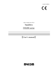
Integrated AC Servo System
MDUG-CM2/09101E-01
Before use, read through this User's Guide to ensure proper use.
In particular, be sure to read "Instructions for Safety" without fail for safety purpose.
Keep this User's Guide at an easily accessible place so as to be referred anytime as necessary.
The contents of this User's Guide are subject to change without notice for the improvement in product,
specification, or usability of this User's Guide.
This User's Guide is only intended to provide information about the product, and dose not guarantee any
results from usage of the product. Muscle Corporation is not responsible for any damages and/or injuries
resulting from the implementation in accordance with the contents of this User's Guide.
Please notify our sales representative if you have some questions or comments with the contents of this
User's Guide.
The contents of this User's Guide do not guarantee or grant rights to patents, copyright, or any other rights to
the intellectual property of Muscle Corporation or any third party. Muscle Corporation is not responsible for
any problems that may occur concerning the intellectual property rights of third parties resulting from the
application of information provided in this User's Guide.
Cool Muscle is a registered trademark of Muscle Corporation.
Microsoft and Windows are registered trademarks of Microsoft Corporation in the United States and other
countries.
Other company names and product names described in this User's Guide are trademarks or registered
trademarks of their respective holders. The trademark notices (TM, ®) are not necessarily appended to
company, system, and product names described in this User's Guide.
© 2007 Muscle Corporation. All rights reserved.
It is prohibited to reprint or copy all or any part of this User's Guide without prior written permission.
PR-001
Instructions for Safety
【Be sure to read before use for safety】
To ensure safe use
To ensure the safe and proper use of our products, it is important that you read this User's Guide thoroughly
prior to its use. Failure to read, fully understand and implement following instructions and precautions may
result in damage to the product, the machine to which it is installed, or operator injury.
About product application
These products are manufactured as a general-purpose part for the application in general industries.
They are not designed or manufactured for equipments or systems which have an affect on human life,
or applications in which faulty operation or failure may result in personal injury or significant damage to
property.
These products shall not be used in applications which require an extremely high degree of reliability and
safety, such as those listed below.
Medical equipment or system that have a direct affect on human life.
Applications that directly affect on the safety of people.
(For example, the operation and control of aircraft, cars, elevators railroads, etc.)
Applications in which failure may significantly damage or impact the society and public.
(For example, nuclear power, electric power, aerospace, public transportation system, etc.)
Equipments or systems used under special environmental condition.
Applications with the same level of importance as those described above.
* When considering the product for use in such special applications, please contact our sales representative.
We ask that you employ fail-safe systems when applying these products to the equipment in which any
failure on its part can be expected to cause a serious accident or loss.
Safety Precautions
Please read following precautions in order to ensure safe and proper use of the product, and avoid dameges
on machinery and injuries to the operators and other people.
This User's Guide should carefully be kept in a convenient place for the operator's easy reference.
PR-002
In this User's Guide, safety precautions are classified as either “Warning” or “Caution”, indicating the level of
hazard seriousness possibly occurred when handling the product incorrectly.
The symbols are explaind below.
Warning
Indicates an imminently hazardous situation which, if not handled
Caution
Indicates a potentially hazardous situation which, if not handled
properly, may result in death or serious injury.
properly, may result in injury or property damage.
Note that some items described as Cautions may result in more serious damage under certain
conditions. Please observe the precautions of both levels because they are important to personnel safety.
“What must not be done” and “What must be done” are indicated by the following symbols.
Indicates a prohibited action
Ex.
"No disassemble"
Ex.
"Grounding"
(what must not be done).
Indicates a necessary action
(what must be done).
PR-003
Warning
Never touch the rotating part of the motor while operating.
The failure could result in injuries.
Take a measure for safety to keep away contact by personel.
Do not touch the motor and driver while power is ON or for some time after
power-OFF.
Temperatures may be high and you may get burnt.
Do not change the wiring while power is ON.
Be sure to remove wiring and unplug a connector after power-OFF.
The failure could result in electric shocks, runaway or damages.
Do not give damage to, apply excessive force to, place something heavy upon,
or pinch the cable.
Do not pull the cable by too much power. The failure could result in damages to connection
section, or electric shocks.
Never disassemble, modify, or repair the product.
Do not open the cover of the product, or disassemble or modify the parts inside.
The failure could result in fire, electric shocks, malfunction or injuries.
Do not install the product on or near combustibles.
Attach the product to noncombustible matter such as metal. The failure could result in fire.
Do not tamper with water, corrosive gas, inflammable gas, flammable
material, or electrically conductive material such as screw or metal piece.
Do not insert metal pieces into the venting holes of enclosure.
The failure could result in fire, electric shocks, or damages.
Be sure to ground the terminal of the earth wire.
Securely ground to prevent electric shocks and to stabilize the potential in the control circuit.
Caution
(environment)
Keep or use the product under the following environmental conditions.
Ambient temperature / Working : 0 to 40 , Storage : -20 to 60 (non freezing)
Ambient humidity : Below 90%RH (non condensing)
Vibration / Shock resistance : Below 9.8ms-2 (1G) / Below 98ms-2 (10G)
Avoid store or use in such an environment where the product is exposed to oil or water.
(It is not waterproof structure.)
Indoor use only (no direct sunlight). No corrosive gas, inflammable gas, oil mist or dust.
PR-004
Caution
(transportation)
The product is precision mechanical equipment.
Do not drop or give any strong impact to the product.
The failure could result in damages or malfunction.
Do not hold the cables or motor shaft when transporting the product.
The failure could result in damages or malfunction.
Do not climb, stand, or put heavy objects on the product.
The failure could result in damages or malfunction.
Do not stack in excess of the specified number of products.
The failure could result in damages or malfunction.
Caution
(installation)
When installing a pulley or coupling to the machine, do not hammer on
the motor shaft.
The failure could result in damages or malfunction..
Be sure to fix the product on the machine firmly.
If fixation is not tight enough, the product may come off while operating.
Be sure to make precise centering between the motor shaft and the machine.
Deviation from the center could result in vibration or damages.
The load inertia moment should be below the recommended load inertia
moment ratio of the motor being used.
If it is too large, desired performance may not be attainable.
Carefully consider the heat radiation of the product, and make sure to
install it in the condition with proper airflow.
Be sure to avoid interference with the heat radiation of motor and driver.
Do not block up a venting hole in the enclosure of driver.
The failure could result in abnormal temperature.
PR-005
Caution
(wiring)
Wiring must always be performed properly and reliably.
Ensure that terminal connection or porarity (+, -) is correct.
The failure could result in damages or malfunction.
Carefully consider the cable clamping method, and make sure that bending
stress and the stress of the cable’s own weight are not applied on the cable
connection section.
The failure could result in damages or burst.
Do not apply a voltage exceeding the specified voltage to the input terminal.
The failure could result in damages or burst.
Do not modify the connector or terminals, etc., on the end of the cable.
The failure could result in damages or burst.
Caution
(usage)
Provide an external emergency stop circuit to ensure that operation can be
stopped and power switched off immediately.
When a trouble occurs, shutoff the power immediately.
Before operation, check the parameter settings to ensure that there are no
operation errors. Connect a load to the products after the successful
trial-operations.
Improper settings may cause some machines to perform unexpected operation,
resulting in damages.
Do not apply a load exceeding the tolerable load onto the motor shaft.
The failure could result in break of the shaft.
Do not turn on or off the power frequently.
The failure could result in degradation of circuit element.
Do not change the parameter settings excessively.
The failure could result in instable or unexpected operation.
PR-006
Caution
(corrective actions)
If any alarm has occurred, eliminate its causes of alarm and secure the safety
before restarting the operation.
The failure could result in damages or burst.
When it is assumed that a hazardous condition may take place at the
occurrence due to a product fault, use an external holding brake mechanism.
If any alarm has occurs, the motor goes into free-run state.
If any product fault has occurred, shutoff the power immediately and do not
turn on the power.
The failure could result in damages or burst.
Caution
(maintenance, inspection)
Only persons who are trained and qualified to work or on electrical
equipment are permitted to maintain or inspect the product.
Incorrect handling or operation could cause electric shocks or damages.
Do not perform a dielectric voltage-withstand test.
The failure could result in destruction of circuit element.
Muscle Corporation is not responsible for any damages resulting
from modifications or repairs made to the product.
About processing of waste
This product should be treated as an industrial waste when it is disposed.
PR-007
INDEX
Chapter 1
Functions and Structure���������������������������������������������������001
1.1. Overview��������������������������������������������������������������������001
1.2. Block Diagram���������������������������������������������������������������002
1.3. Product Code Scheme�������������������������������������������������������002
1.4. Parts Description������������������������������������������������������������003
1.5. Motor's Rotating Direction����������������������������������������������������003
1.6. Status LED������������������������������������������������������������������004
1.7. Control Type�����������������������������������������������������������������005
1.7.1. Pulse Type (P Type)�����������������������������������������������������005
1.7.2. Computer Type (C Type)�������������������������������������������������005
1.7.3. Interpolation Type (R Type)����������������������������������������������005
Chapter 2
Installation����������������������������������������������������������������006
2.1. Operating Condition����������������������������������������������������������006
2.2. Mounting to Machinery�������������������������������������������������������006
2.2.1. General Notes�����������������������������������������������������������006
2.2.2. Coupling / Centering����������������������������������������������������007
2.2.3. Allowable Shaft Load����������������������������������������������������007
2.2.4. Notes for Shaft Load����������������������������������������������������008
2.3. Notes for Cabling������������������������������������������������������������009
Chapter 3
Wiring and Connections���������������������������������������������������� 010
3.1. Typical Connection Example�������������������������������������������������� 010
3.2. Connector Pin Layout and Functions������������������������������������������ 011
3.3. Connecting to Power Supply�������������������������������������������������� 013
3.4. Connecting to Equipments���������������������������������������������������� 014
3.4.1. Connection for Host Communication�������������������������������������� 014
3.4.2. Connection for Pulse Input����������������������������������������������� 015
IN-001
3.4.3. Digital Input/Output����������������������������������������������������� 016
3.4.4. Connection for Analog Input/Output�������������������������������������� 016
3.4.5. +5V Output������������������������������������������������������������� 016
3.5. I/O Circuit ������������������������������������������������������������������ 017
3.6. Connection Example��������������������������������������������������������� 018
Chapter 4
Communication Functions������������������������������������������������� 019
4.1. Communication Software Overview ������������������������������������������� 019
4.2. Confirming Communication��������������������������������������������������� 019
4.3. Communication Method������������������������������������������������������ 021
4.4. Communication Time���������������������������������������������������������022
4.4.1. Transmission Time�������������������������������������������������������022
4.4.2. Response Time���������������������������������������������������������� 023
Chapter 5
Operating the Motor������������������������������������������������������� 024
5.1. Basic Motion����������������������������������������������������������������� 024
5.2. Multiple Axes Control Motion������������������������������������������������� 025
Chapter 6
Input/Output Functions���������������������������������������������������026
6.1. Input / Output Functions�����������������������������������������������������026
6.1.1. Digital Input�������������������������������������������������������������026
6.1.2. Digital Output����������������������������������������������������������� 027
6.1.3. Analog Input�������������������������������������������������������������028
6.1.4. Analog Output�����������������������������������������������������������029
6.2. I/O Signal according to Control Type������������������������������������������029
6.2.1. Pulse Input�������������������������������������������������������������� 029
Chapter 7
Various Other Functions���������������������������������������������������030
7.1. Origin Search����������������������������������������������������������������030
7.2. Push Motion�����������������������������������������������������������������030
7.3. Manual Jog and Feed��������������������������������������������������������� 031
7.4. Torque Control��������������������������������������������������������������� 031
IN-002
7.5. Arithmetic/Logical Operation Function���������������������������������������� 031
7.6. PLC Function���������������������������������������������������������������� 031
7.7. Reversal of Coordinate�������������������������������������������������������032
7.8. Circular / Linear Interpolation (optional)���������������������������������������032
7.9. Protection/Safety Features���������������������������������������������������032
Chapter 8
Maintenance and Inspection �����������������������������������������������033
8.1. Maintenance�����������������������������������������������������������������033
8.2. Troubleshooting��������������������������������������������������������������034
8.2.1. Communications���������������������������������������������������������034
8.2.2. Motor�������������������������������������������������������������������034
8.2.3. Motion������������������������������������������������������������������034
Chapter 9
Characteristics �����������������������������������������������������������035
9.1. Basic Specifications����������������������������������������������������������035
9.2. Electric Specifications�������������������������������������������������������� 037
9.3. Dimensions������������������������������������������������������������������038
Chapter 10
Peripherals���������������������������������������������������������������042
10.1. Cables����������������������������������������������������������������������042
Revision History ����������������������������������������������������������045
IN-003
Explanation of icon
Icons used in this User's Guide.
Warnings and notices
Important points
Supplemental explanations
Bundled Items
a :
c Refer to 3.1)
CM2 package includes CM2 and following cables.( #
Cable
Application
500mm
one side connector
accessory
a
power supply
cable
500mm
accessory
b
one side connector
communication
cable
500mm
one side connector
c
accessory
I/O cable
IN-004
Chapter 1
Functions and Structure
1.1. Overview
The COOL MUSCLE 2 (CM2) is the world smallest integrated AC servo system that combines motor,
encoder, driver, controller, PLC and power supply. The use of its own program language " CML " ( COOL
MUSCLE Language ) allows easy creation and control of motion. CML is a powerful motion programming
language that simplifies and supports PTP motion, interpolation function* and torque control. CM2 provides the
highest system solution. (*optional)
Features of CM2
Motor
CM2 is based on an AC servo motor allowing for high speed, Max.8000min.
100W, 200W and 400W models are available.
Encoder
Muscle's unique magnetic encoder gives CM2 a Max. 50,000 ppr, and realizes the smooth motion and
high-accuracy positioning.
Driver
An ultra compact driver incorporates closed loop vector control.
Muscle's unique control technology eliminates the servo tuning.
Controller
Various kinds of motion as PTP motion, interpolation function (optional) and torque control are supported.
Muscle's original OS is built in.
Integrated PLC Function
CM2 has 6 inputs and 4 outputs.
A totally new integrated AC servo system incorporates PLC function as arithmetic / logical operation and
more.
Integrated Power Supply
Motor control/drive power supply is built in!
CM2 can be connected directly to AC100V-240V power source without conversion.
Communication
Two RS-232C ports.
Multi-axis network can be easily created by the daisy chain connection.
001
Functions and Structure
Chapter 1
1.2. Block Diagram
Power Supply
Input
CM2
Power
Unit
Driver Interface
Controller
DC-DC
Converter
Motor
Motor
Driver
(Amplifier)
Communication
Interface
Communication
Line
Input/Output
Interface
Input/Output
Signal
Magnetic Encoder
(Detect Speed and
Position)
1.3. Product Code Scheme
Product code scheme is described as below.
CM2-C- 56 B 10 A-R
Control Type
Motor size
P Pulse
C Computer
R Interpolation
56
60
Motor
Series
56mm
60mm
Motor Output
10
20
40
100W
200W
400W
CM2 Model numbers are as below.
Cool Muscle 2 names
COOLMUSCLE2 CM2 56
Model #
CM2-*-56B10A-*
COOLMUSCLE2 CM2 60
100W *Type
200W *Type
100W *Type
COOLMUSCLE2 CM2 60
400W *Type
CM2-*-60A40A-*
COOLMUSCLE2 CM2 56
002
CM2-*-56B20A-*
CM2-*-60A10A-*
Shaft end (*Option)
R
K
D
W
Round shaft
Keyway *
D-cut *
Double D-cut *
Output
Chapter 1
Functions and Structure
1.4. Parts Description
Each part of CM2 is as below.
Status LED
LED Cover
Power Supply
Connector
Power Supply Cable
Mounting
holes
(4 corners)
I/O Connector
Driver
Case
Shaft
Slave Connector
Host Connector
I/O Cable
Flange
1.5. Motor's Rotating Direction
The rotationg direction means as drawn in right.
CW (Clockwise) :
Facing to the output shaft, the motor shaft rotates in
Clockwise direction.
CCW (Counterclockwise) :
Facing to the output shaft, the motor shaft rotates in
Counterclockwise direction.
003
Chapter 1
Functions and Structure
1.6. Status LED
Status LED lights as follows by the status of CM2. (Status LED can be inactivated by parameter setting)
Status LED
Pattern of lighting / blinking
Status of CM2
5 SEC
Light
Blue
Lighting
ON
Servo ON
Light
OFF
Lighting
Motor free
ON
by CML command
or input function
OFF
0.5 SEC
Overflow of
Blinking ON
once
position error
OFF
Blinking ON
Over voltage
twice
OFF
Red
Blinking ON
Overload
3times
OFF
Blinking ON
Temperature error of
4times
driver
OFF
Blinking ON
Push motion error
5times
OFF
Blinking ON
Emergency stop
6times
OFF
004
Chapter 1
Functions and Structure
1.7. Control Type
Control types of CM2 include Computer, Pulse and Interpolation allowing you to choose the appropriate type for
your application.
1.7.1. Pulse Type (P Type)
Pulse type CM2 can replace the existing pulse controll unit.
Input methods for Pulse type include CW/CCW pulses and Pulse/ Direction style. This input method can be
selected by parameter K36. Please refer to the CML User’s Guide for more information.
1.7.2. Computer Type (C Type)
The operation controlled by a command or a program are possible. C type CM2 can be operated in the
following methods.
Direct Mode
If your application requires complicated motion or arbitrary motion, you can send CML commands directly to
CM2 via PC or embedded computers as needed. Immediate motion of CM2 is triggered and executed every
time CML commands are sent from computer.
This mode is useful for debugging the programs or test runs. Please refer to the CML User's Guide for more
information.
Program Mode
CM2 operates in accordance with a pre-defined program using CML. For the application which requires
repetitive motion, it is realized by executing pre-programmed positioning program stored in CM2, eliminating
the need for an external controll unit. Pre-loaded programs in CM2 can be set to run using a switch connected
to input, PC or PLC.
Please refer to the CML User's Guide for more information.
1.7.3. Interpolation Type (R Type)
R type CM2 has the function of Circular/Linear Interpolation in addition to the function of Computer Type.
Circular Interpolation function can easily generate an arc trajectory only by specifying radius or center point of
circle without a complex hand calculation and describing the calculating formula.
005
Chapter 2
Installation
Installing in an improper location or mounting to machinary incorrectly, CM2 could result in abnormal behavior
or an unpredictable accident. Please read the following cautions to ensure safe and proper use of CM2.
2.1. Operating Condition
Please refer to Section 9.1 for operating and storage conditions.
The following instructions should also be fully noted.
Indoor where there is not direct sunlight on the product.
Cooling ventilation is properly considered.
No dust, metal particles, corrosive gas, flammable gas, oil mist.
No drop of water and cutting oil.
Please note that CM2 is not environmentally sealed. Using CM2 in a place where water or oil
gets into it may cause insulation failure or short-circuit.
Use in a place where inspection and cleaning are easy to do.
* Please contact us when the motor is required for more demanding conditions.
2.2. Mounting to Machinery
2.2.1. General Notes
Mounting Direction
CM2 can be mounted horizontally or vertically.
Impact / Vibration
Please avoid mounting CM2 where excessive impact and vibrations occur.
Protect CM2 from impact such as hammering during mouting. Never apply any direct impact to the motor shaft.
006
Chapter 2
Mounting CM2
2.2.2. Coupling / Centering
Use a coupling when connecting the motor to a machine
Motor
to avoid unnecessary load. Make sure that the motor shaft
and the machine center are properly aligned.
Use a flexible coupling with high torsional stiffness. Use of
a flexible coupling with low torsional stiffness may cause
machine center
motor axis center
Coupling
unstable motion.
degree of eccentricity
When the machine center and the motor shaft are not
Motor
properly aligned, vibration may occur, resulting in damage
to the motor bearings. Please make sure to align the motor
shaft with the mashine center within the error tolerance as
the diagram in the right. Do not apply impact or force to the
motor axis center
machine center
Coupling
motor shaft during mounting a coupling.
degree of parallelization
2.2.3. Allowable Shaft Load
Allowable Radial Load and Thrust Load onto the motor shaft
are described in 9.1, Specification. Design the machinery
to ensure that shaft load does not exceed the allowable
values.
Radial Load (Fr) : Perpendicular force applied to the
shaft end.
Thrust Load(Fs) : Parallel force applied to the shaft end.
007
Chapter 2
Mounting CM2
2.2.4. Notes for Shaft Load
Radial Load
Excessive radial load could damage the motor bearings.
Belt Drive
When a pulley is directly mounted onto the shaft,
take note of radial load caused by belt tension.
To prevent slipping and respond to overload, a
wide belt with strong tension tends to be used for
design on the safe side. Moreover, this tendency
may be increased by the adjustment not using a
measurement tool.
Gear drive
When a gear is directly mounted onto a motor
shaft, radial load is occurred.
The larger radial load is caused by using smaller
gears to obtain high reduction ratio. Please make
sure that the axial load is within the values of
specifications.
Overhang load
When the motor shaft is overhung, a vertical force
onto the overhung part has a big influence on the
motor shaft.
Overhang load is multiplied by the leverage effect,
stressing the motor shaft bearing. The longer the
overhung length, the larger the overhang load.
Moment load is applied ( see the illustration in the
right) to the motor shaft that is overhung. A tension
force is applied to the top half of the shaft and
compression forced is applied to the bottom half of
tension
the shaft. During the shaft rotation, these opposite
forces alternate and stress the shaft, and continued
rotation over the long term could result in break.
008
compression
Chapter 2
Thrust Load
Large thrust load could damage the motor shaft bearings.
A large thrust load could even move the shaft , damaging
an encoder that is mounted at the other end of the shaft.
When mounting a worm gear directly onto the motor
shaft, a large thrust load occurs. Make sure that a thrust
load is not applied to the motor shaft when mounting or
taking off a gear, pulley or coupling.
2.3. Notes for Cabling
Make sure that bending stress or tension force is not applied
to the cable.
Do not connect or disconnect connectors when the motor is
powered. Make sure that the power is OFF before connecting or
disconnecting the connector.
Do not pull the cable forcefully or use the cable to carry or
hang CM2. This may damage the connectors.
009
Mounting CM2
Chapter 3
Wiring and Connections
3.1. Typical Connection Example
Single-phase
a
Three-phase
c = refer to bundled items list
= refer to 3.2
= refer to 10.1
Securely ground
the earth of CM2
Noise filter
Noise filter
①
a⑤
PC
to power supply
b⑥
②
to host
③
to slave
to power supply
④
⑦
to I/O equipment
Programmable
Display Terminal
c ⑧
to I/O equipment
PLC
010
Chapter 3
Cabling and Connections
3.2. Connector Pin Layout and Functions
Connector Pin layout for each CM2 cable is as below.
Pin layout
①
Power supply Connector 1-178128-4 (Tyco Electronics AMP)
1
No.
1
2
3
4
2
3
4
②
③
④
Color
Red
White
Black
Green-Yellow
Host Connector XAP-03V-1 (JST)
1
2
3
No.
1
2
3
Color
Brown
Red
Orange
3
2
1
No.
1
2
3
Color
Yellow
Green
Blue
Slave Connector XARR-03VF (JST)
I/O Connector XADRP-20V (JST)
1
2
No.
1
2
3
4
5
6
7
8
9
10
19
20
011
Color
Brown
Red
Orange
Yellow
Green
Blue
Purple
Gray
White
Black
No.
11
12
13
14
15
16
17
18
19
20
Color
Brown
Red
Orange
Yellow
Green
Blue
Purple
Gray
White
Black
Chapter 3
Cabling and Connections
Connector Pin Function List
Cable
Connector
Name
①
Power supply Power supply
Cable
Connector
② Host
Connector
③ Slave
Connector
I/O
Cable
④ I/O
Connector
No.
Pin name
1 R / L1
2
3
4
1
S
T / L2
E
RXD0
Functions
3 phase / Single phase AC input
3 phase AC input
3 phase AC / Single phase AC input
Earth
RS-232C, Receive data from host
2 TXD0
3 GND
RS-232C, Transmit data to host
Communication GND
1
2
3
1
2
3
4
5
6
7
8
9
10
11
12
13
14
RS-232C, Transmit data to slave
RS-232C, Receive data from slave
Communication GND
+5V Output (0.2A max)
Digital Input 1+
CW+
Pulse+
Digital Input 1CWPulseDigital Input 2+
CCW+ Direction+
Digital Input 2CCW- DirectionDigital Input 3
Digital Input 4
Digital Input 5
Digital Input 6
Common for digital input3~6
Digital Output 1
Digital Output 2
Digital Output 3
Digital Output 4
TXD1
RXD1
GND
+5V
INPUT1+
INPUT1INPUT2+
INPUT2INPUT3
INPUT4
INPUT5
INPUT6
INPUT COM
OUTPUT1
OUTPUT2
OUTPUT3
OUTPUT4
15 OUTPUT COM Common for digital output1~4
16 ANALOG IN
Analog Input
17 ANALOG OUT Analog Output
18 N.C.
19 GND
20 GND
Signal Ground
Signal Ground
012
Chapter 3
Cabling and Connections
3.3. Connecting to Power Supply
Connect CM2 Power Supply cable to AC power supply.
Power supply cable
AC
Power supply
Connector
Power supply
cable
CM2
Make sure that the power is OFF while connecting the cables.
Power ON after confirming the wiring is thoroughly correct.
Securely ground the earth of CM2.
Single-phase
Three-phase
Three-phase
Single-phase
Noise filter
Noise filter
CM2
013
CM2
Chapter 3
Cabling and Connections
3.4. Connecting to Equipments
Up to 15 CM2s can be daisy-chained by connecting the host connector to the slave connector of each CM2.
Use of a daisy chain cable (option) allows a longer distance communication between CM2s. Among plural
CM2s, only the host connector of the 1st Axis (CM2) must be connected to a host such as a PC. And if
necessary, connect the I/O connector with each external equipment by using an I/O cable.
Host
Slave
Connector
Host
Connector
Host
Connector
Daisy Chain Cable
I/O
Connector
I/O Cable
Extend
Equipment
Extend
Equipment
Extend
Equipment
Make sure that the power is OFF while connecting the cables.
Power ON after confirming the wiring is thoroughly correct.
3.4.1. Connection for Host Communication
The connecting diagram of an attached communication cable and a D-Sub connector linked to the host
is as follows.
9 Pin
D-Sub Connector
Accessory
Communication Cable
014
Host Connector
CM2
Chapter 3
Cabling and Connections
3.4.2. Connection for Pulse Input
For Pulse type CM2, Input 1 and Input 2 are assigned to CW/CCW pulse Input or Pulse/Direction command
Input. Each signal should be input between Input 1+ and Input 1-, and between Input 2+ and Input 2-.
Connecting to Line Driver (Differential type) Output
2
CRD
INPUT 1
CW Pulse
CW Pulse
3
CM2
4
CRD
CCW Pulse
CCW Pulse
5
INPUT 2
(example of CW/CCW pulse input)
Connecting to Open Collector Output
DC+5~24V
2
CRD
INPUT 1
Pulse
3
Pulse
CM2
4
CRD
Direction
5
INPUT 2
Direction
0V
(example of Pulse/Direction command input)
The polarity of input voltage for Input 1+ (Input 2+) is plus(+) to Input 1- (Input2-).
As each input (Input 1, Input 2) is equipped with current regulative diode (CRD),
the input current can be 8-12mA.
Interface using Line Driver Circuit is strongly recommended.
As Open Collector interface is highly influenced by noise, deviation in position could occur.
Moreover, caution should be exercised in case of long distance wiring.
015
Chapter 3
Cabling and Connections
3.4.3. Digital Input/Output
INPUT 1, 2
Input 1 and Input 2 can be used as digital except for Pulse type. Please refer to 4.4.2 for connection.
INPUT 3, 4, 5, 6
An optical coupler device is used for Input 3-6 circuitry shown below. Each signal should be input between Input
3,4,5,6 and Input COM.
CM2
CM2
+24V
INPUT COM
INPUT COM
0V
10
10
Switch
Switch
10KΩ
10KΩ
6~9
6~9
INPUT 3~6
+24V
INPUT 3~6
0V
Plus or minus polarity is acceptable for the input voltage between Input 3, 4, 5, 6 and Input COM.
Each input (Input 3, 4, 5, 6) is equipped with resistor 10K in series.
OUTPUT 1, 2, 3, 4
A FET device is used for Output 1-4 circuitry shown below.
Each FET output is between Output 1,2,3,4 and Output COM.
CM2
CM2
Vc
OUTPUT COM
0V
OUTPUT COM
15
15
1KΩ
Vc
1KΩ
11~14
OUTPUT 1~4
OUTPUT 1~4
11~14
0V
Plus or minus polarity is acceptable for the applied voltage between Output 1, 2, 3, 4 and Output COM.
Each output (Output 1, 2, 3, 4) is equipped with resistor 1K in series.
Allowable load current for each output (Output 1, 2, 3, 4) is 20mA.
3.4.4. Connection for Analog Input/Output
ANALOG IN
Apply analog voltage 0-5V between ANALOG IN (16pin) and GND (19, 20pin) of CM2.
ANALOG OUT
Analog voltage will be output between ANALOG OUT (17pin) and control GND (19, 20pin) of CM2. You can
monitor the analog voltage by Oscilloscope.
3.4.5. +5V Output
+5V
Regulated DC +4.8V (typ.) is output between +5V (1 pin) and GND (19, 20pin). Maximum output current is 200mA.
016
Chapter 3
3.5. I/O Circuit
INPUT1+
INPUT2+
INPUT1,2
Polarity Fixed
1KΩ
INPUT1INPUT2-
INPUT COM
Input
INPUT3,4,5,6
No Polarity
10KΩ
INPUT 3,4,5,6
ANALOG IN
Polarity Fixed
ANALOG IN
10KΩ
0.1μF
OUTPUT COM
OUTPUT 1,2,3,4
No Polarity
1KΩ
OUTPUT 1,2,3,4
Output
ANALOG OUT
Polarity Fixed
ANALOG OUT
017
Cabling and Connections
Chapter 3
3.6. Connection Example
018
Cabling and Connections
Chapter 4
Communication Functions
Command transmission via serial communication is possible between CM2 and a host such as PC.
It allows you to set parameters, create motion programs, save the data into CM2’s integrated memory, execute
motion commands, and also monitor motor status. CML is available for parameter settings, creation of motion
programs or command input.
4.1. Communication Software Overview
With following software, communication between CM2 and PC is possible.
Hyper Terminal
Hyper Terminal is the communication software attached to Windows OS and you can input the text-based
commands.
CoolWorks Lite
CoolWorks Lite (hereafter CWL) is CML compatible utility software, has user-friendly interface and assists easy
operation of CM2.
With CWL, you can modify parameters and data, save them, jog the motor, plot the motor data on a graph
easily.
The latest CWL can be downloaded for free from the following web site: http://www.musclecorp.com/.
Please refer to CWL User Manual for more information.
*CWL would be updated without notice.
4.2. Confirming Communication
According to the following procedures, please confirm that the communication between PC and CM2 is
established. In this section, the communication method of HyperTerminal is introduced.
1) Start up PC
2) Start up HyperTerminal
Click [Start] in Windows,
select [All Programs]→
[ Accessories]→
[Communication]→
[Hyper Terminal].
019
Chapter 4
Communication Functions
3) Set connection settings for Hyper Terminal
In the [Connection Description] Window.
[Name] … Use a name that is easy to understand.
[Icon] ex. Cool Muscle
… Choose an Icon of your choice.
Click [OK].
[Connect To] … Choose a COM port that CM2 is connected to.
Click [OK].
Open the Control panel, click [Performance
and Maintenance] and then [System].
Choose [Hardware] Tab on the opened window and
then click [Device Manager].
The available COM ports are displayed in the tree
selection [Ports (COM & LPT)] .
In the [COM
Properties] window, set each item as below.
[Bits per second] … 38400
[Date bits] …8
[Parity] … None
[Stop bits] …1
[Flow control] … None
Click [OK].
Default value of CM2's communication
baud rate is 38400.
4) Power-ON CM2 and confirm communication between
PC and CM2.
CM2’s version information appears when there is
communication between CM2 and PC is established.
It might take a few minutes to establish communication
when CM2 is connected to PC for the first time.
5) Save communication settings.
Power-OFF CM2, and click the X at the top right corner of Hyper Terminal Window. Dialog box will appear and
ask if you want to save the settings as the name you entered in step 3. Click [Yes] to save the settings.
020
Chapter 4
Communication Functions
4.3. Communication Method
In this section, communication method with Hyper Terminal is introduced. Please refer to CoolWorls Lite User
Manual for CWL instructions.
1) Start up Hyper Terminal.
Go to [Start] in Windows [All Programs]→[Accessories]→[Communications]→[HyperTerminal].
Select the connect settings for CM2, named in the Connection Discription and saved before.
2) Send commands and programs.
Enter CML commands in the terminal window and press "Enter
" key to send commands to CM2.
CM2 executes motion or reacts to commands.
To transfer a text file that is created in editor application such as Word, click [Transfer] in the Menu Bar → [Send
file]. Select a file that you want to transfer.
Please refer to CML User's Guide for CML commands and programs.
3) Save and print communication log.
To save communication log, click [Transfer] in the Menu Bar → [Text Capture].
To print communication log, click [Transfer] in the Menu Bar → [Capture and Print].
021
Chapter 4
Communication Functions
4.4. Communication Time
4.4.1. Transmission Time
Parameter
When the change of parameters is performed with a host such as PC, the data shall be sent to CM2 and written
into the internal memory (EEPROM) with predefined timing. The communication data processing is sometimes
delayed because the writing time will take longer in proportion to the number of parameters to be changed.
Set the appropriate Wait Time between parameter transfer, and you can get the stable communication and
over-writing new data without fail. The Wait Time can be set according to the communication speed (baud rate)
and number of parameters to be changed as shown in the following graph.
The graph shows only a rough indication by simple calculation. Set the affordable Wait Time.
Parameter transfer
Parameter transfer
Wait Time T
The time between a delimiter(, or CR) and the
first character of the next parameter transferred.
T
T
Wait Time
Wait Time
The relationship between number of parameters transferred / over-written and required Wait Time
19.2kbps
38.4kbps
7
6
Wait Time (msec)
5
4
3
2
1
0
20
30
40
50
60
70
80
Number of parameters transferred / over-written
* Wait Time will not be required in 9600 bps. But the communication will be more stable if 1msec time interval is
set between each transferred parameter.
CM2's communication buffer could be overflowed by a delay of communication data processing when
a lot of parameters are transferred to CM2 and over-written at a time with high communication speed.
Command
Set more than 1msec time interval between the commands transferred.
Query
Send another query after receiving the response for the query before.
022
Communication Functions
Chapter 4
4.4.2. Response Time
When more CM2 are used in daisy-chained network, more time will be needed for transmission of data. Higher
communication speed can realize higher response.
Ex.: When the following Program Bank is executed with 38400bps in the configuration of 6 CM2s, the response
time goes as follows.
B1.1
A1.1, S1.1, P1.1, A1.2, S1.2, P1.2, A1.3, S1.3, P1.3, A1.4, S1.4, P1.4, A1.5, S1.5, P1.5, A1.6, S1.6, P1.6
END
$.1,$.2,$.3,$.4,$.5,$.6
[1.1
[
Send
Execute
1
[
1
?msec
0.3msec
1st CM2
3.5msec
.
1
.
?msec
0.3msec
CR
1
?msec
0.3msec
?msec
0.3msec
0.3msec
This time will be different in each case
[1.1CR → "[", "1", ".", "1", "CR" 5 characters. It will take 10bit / 38400
(bit/sec) = 0.00026… 0.3msec for 1 character, 0.3×5=1.5msec in total.
The internal processing time after receiving "CR" shall be Max. 2msec.
After sending data, it theoretically takes Max. 3.5msec before motion starts.
8msec
2nd CM2
A1.2,S1.2,P1.2, (15 characters)
0.3×15=4.5, the 2nd CM2 starts the motion Max. 4.5msec after the 1st CM2.
12.5msec
3rd CM2
A1.2,S1.2,P1.2,A1.3,S1.3,P1.3, (30 characters)
0.3×30=9, the 3rd CM2 starts the motion Max. 9msec after the 1st CM2.
17msec
4th CM2
A1.2,S1.2,P1.2,A1.3,S1.3,P1.3,A1.4,S1.4,P1.4, (45 characters)
0.3×45=13.5, the 4th CM2 starts the motion Max. 13.5msec after the 1st CM2.
21.5msec
5th CM2
A1.2,S1.2,P1.2,A1.3,S1.3,P1.3,A1.4,S1.4,P1.4,A1.5,S1.5,P1.5, (60 characters)
0.3×60=18, the 5th CM2 starts the motion Max. 18msec after the 1st CM2.
6th CM2
26msec
A1.2,S1.2,P1.2,A1.3,S1.3,P1.3,A1.4,S1.4,P1.4,A1.5,S1.5,P1.5,A1.6,S1.6
, P1.6, CR (75 characters)
0.3×75=22.5, the 6th CM2 starts the motion Max. 22.5msec after the 1st CM2.
* By defining only the “A” and “S” data for ID1 6 in the first line and “P” data for ID1
the time delay between each motor shall be shorten to approximately 1.5msec.
023
6 in the second line,
Chapter 5
Operating the Motor
5.1. Basic Motion
All of CM2’s motion is operated by our unique CML Command. Please refer to CML User Manual for more
information.
PTP Positioning
CM2 moves to P1, P2, and P3, pausing for the time set by T1 at each point.
Speed
S2
A1
A1
A1
P1
A1
A1
P3
S1
A1
P2
Time
T1
T1
Speed setting
Speeds can be defined as shown in the diagram above to make a stable speed at each position or to change
speed at specified positions.
Accelerations and Decelerations setting
Unless set by parameters, acceleration and deceleration are the same.
Acceleration (A1) and Deceleration ( A2) can be set separately as shown in the diagram below.
Speed
S1
A1
A2
P1
P2
Time
Merged Motion
Merged Motion is possible as CM2 passes each point without stopping and move to the final position (Merged
Motion). You can change the speeds and accelerations can be changed at each passing point.
Speed
S3
A2
S2
A1
A2
P3
S1
P2
A1
P1
Time
024
Chapter 5
Operating the motor
Creeping Speed
Creeping speed is the initial speed with which the motor initiates motion and also the speed at which the motor
approaches the target position. By changing the creeping speeds, response time can be adjusted and tact time
will be faster. When the creeping speed is set too high, vibrations may occur and the motor may not move.
Speed
Creeping Speed
Time
5.2. Multiple Axes Control Motion
Parameters, Program Banks, and Ladder Logic Banks can be set to each CM2 on the daisy-chain network.
Since all the status and I/O information can be shared between motors, CM2 realizes the high performance
multiple axes control.
Information shared between CM2s.
B1.1
A1.1,S1.1,P1.1
A1.2,S1.2,P1.2
A1.3,S1.3,P1.3
END.1
B1.2
A1.1,S1.1,P1.1
A1.2,S1.2,P1.2
A1.3,S1.3,P1.3
END.2
Program Bank CML
written in the memory.
Daisy-chained
Up to 15 motors
025
B1.15
A1.1,S1.1,P1.1
A1.2,S1.2,P1.2
A1.3,S1.3,P1.3
END.15
Chapter 6
Input/Output Functions
6.1. Input / Output Functions
The CM2 has 6 Digital Inputs, 4 Digital Outputs, 1 analog input and 1 analog output (Monitoring). Various
functions can be assigned to these inputs and outputs by parameters.
6.1.1. Digital Input
Signal classification
at Level
at rising
or
falling edges
Functions
Description
General Use
General Use for I command
Origin sensor
Origin sensor signal
Manual feed CW
ON: continuous CW direction motion
Manual feed CCW
ON: continuous CCW direction motion
Stop Ladder Logic Bank
Stop the Ladder Logic Bank in operation
CW direction limit sensor
Used for the limit sensor in CW direction
Emergency stop
Emergency stop when the input signal is ON
Stop Program Bank
Stop motion and Program Bank execution
CCW direction limit sensor
Used for the limit sensor in CCW direction
Alarm Reset / Pause
Alarm reset or pause motor
Motor Free
Disable motor (rising edge)
Enable Motor
Enable motor( falling edge) (Servo ON)
Position counter reset
Set the current position to 0. ( reset position counter)
Execute next line
Execute next program line
Execute previous line
Execute previous program line
Execute Program Bank 1
Execute Program Bank 1
Origin Search
Start origin search
Manual jog CW
Jog motion in CW direction.
Manual jog CCW
Jog motion in CCW direction.
026
Chapter 6
Input/Output Functions
Use of virtual signals allows to assign more functions to each input.
The CM2 generates 2 input signals with a time delay based on the actual signal. Functions can be assigned to
rising edge / falling edge / target voltage level of a signal.
For example, assign "stop" to a quick response signal’s rising edge, "motor free" / "enable motor" to slow
response signal’s rising / falling edges.
High
Low
Level
Rising edge
Stop
Quick response
signal
Level
Rising edge
Falling edge
Enable Motor
Motor Free
Slow response
signal
Time delay
6.1.2. Digital Output
Signal
Output
signal
Functions
Description
In-Position
In-position signal
Alarm
Alarm signal
General Output
General output; Command O/ Command F turn output
signal ON / OFF.
Completion of origin search
Output In-position signal only when the origin search is
completed.
In-position signal in Merge motion In-position signal at each point in merge motion.
Position Mark Output
Turns the output On/OFF at a set interval.
Motor Free Signal
Outputs signal during motor free
Push Motion
Outputs signal during push motion
027
Chapter 6
6.1.3. CW
Analog Input
Input/Output Functions
CCW
Analog input/output functions are an ideal solution for feed systems and valves.
If the analog input voltage is applied when CM2 is powered ON, it interferes with the threshold on either 0V or
5V. Therefore make sure to apply the analog voltage that adapts the motion before powered ON.
Signal
CW Functions
Description
The speed control in proportion to input voltage level from 0.2V to 4.8V.
Input voltage 2.6V to 4.8V : Increase speed in CW direction
Input voltage 2.4V to 0.2V : Increase speed in CCW direction
Input voltage 0.2V to 4.8V : Increase speed either in CW or CCW direction
CW
The maximum rotation speed is set by a parameter.
Position
Max
Speed Control
Speed
Speed
CW/Max
CWorCCW
Max
(Rotation Direction /
CCW
Speed)
0
0
Input
Voltage
(V)
Input
Voltage
0.2
4.8
<Position Control>
CCW/Max
0
CW
Input
Voltage
(V)
0.2
2.4 2.6
Input
Voltage
(V)
0
0.2
4.8
<Speed Control>
The position control in proportion to
input voltage level from 0.2V to 4.8V.
4.8
Speed
Position
Max
CW/Max
The maximum travel range is set by a
Position Control
parameter.
0
(Rotation Angle or
Distance)
0
Input
Voltage
(V)
0.2
4.8
<Position Control>
028
CCW/Max
0
0.2
Chapter 6
Input/Output Functions
6.1.4. Analog Output
OP Amp usage is recommended
Signal
Functions
Analog Output
(Monitoring)
Description
Target position
Target position ( pulses)
Target position magnified by 8
Target position data magnified by 8
Current position
Current position ( pulses)
Current position magnified by 8
Current position data magnified by 8
Position error
Position error ( pulses)
Position error magnified by 8
Position error data magnified by 8
Current speed
Current speed(rpm)
Current speed magnified by 8
Current speed data magnified by 8
Current torque
Current torque (kgfcm)
Current torque magnified by 8
Current torque data magnified by 8
6.2. I/O Signal according to Control Type
6.2.1. Pulse Input
INPUT 1 and INPUT 2 are used for Pulse Input. The rotation of motor is controlled through the command pulse
signal. The motor angle is proportional to a number of pulses and the motor speed is proportional to the pulse
frequency.
Method
Symbol
Pulse
Function
Pattern of Signal and Motion
CW
CCW
CW
CCW
Command pulse
Pulse /
t1
t1
Direction
Direction
CW Pulse
Rotation direction
t2
t2
t2
t2
CW
CW
CW direction
CCW
CCW
command pulse
CW / CCW
CCW Pulse
t2
t2
t1
t1
CCW direction
t1
t1
command pulse
t2
t2
* Pulse frequency : Max. 500Kpps
* The width of pulse : Min. 0.8 sec (t1>=0.8 sec)
* Pulse rise / fall time of input signal should be set to no more than 0.1 sec
* The time between a direction pulse and command pulse : More than 5 sec (t2>=5 sec)
029
t1
t1
Chapter 7
Various Other Functions
7.1. Origin Search
There are two origin search methods as using stopper and origin sensor.
Using Stopper
The origin search method using stopper function eliminates the need for origin sensor.
The origin search is completed by detecting the set torque when pushing a stopper.
The torque, speed, acceleration and direction for the origin search can be set by parameters.
Using Origin sensor
The origin search with an external origin sensor.
The speed, acceleration and direction for origin search can be set by parameters.
7.2. Push Motion
CM2 can perform push motion within the set torque limit.
The diagram below shows the push motion towards P2 with S1 after passing P1 with S3.
The torque limit and time duration for push motion need to be defined by parameters K60 and K61.
Speed
S3
A1
A1
When there's no object
CM2 goes into
Push Motion Error.
S1
P1
P2
0
Time
Torque
Torque limit set
by K60
Pushing
0
Time
Time duration set by K61
Push Motion
030
Chapter 7
Various Other functions
7.3. Manual Jog and Feed
Manual jog makes the motor move incrementally by numbers of pulses set by parameter for an one-shot
signal input. This is useful for fine adjustments. Manual feed makes the motor move in a specified direction
continuously while the signal is ON. The motor stops when the signal is OFF. Speed and direction can be set by
parameters.
7.4. Torque Control
This feature allows an output torque control or feedback
control by connecting CM2 to an external torque sensor.
Various torque controls such as push control common in
pneumatic sliders and constant tension control are possible.
7.5. Arithmetic/Logical Operation Function
Arithmeticl/logical operations can be executed in Program Banks, using information such as defined data in the
memory, current position, speed, torque of motor and I/O status.
It is possible to operate the complex control, using arithmetic/logical operations for position, speed and torque
of motor, that is adaptable to a nonlinear application too.
Furthermore, the range of motion control can be expanded with using arithmetic/logical operations such as
comparison of defined values and conditional branching by logical operation.
7.6. PLC Function
CM2 has software PLC function, and the sequential logic can be defined by CML.
The processing of PLC function runs in the background along with the operation of motor and makes it possible
to execute various processes in conjunction with motor status, I/O status and etc.
PLC function implemented in CM2 supports complex motion without equipping external PLC as a host controller.
031
Chapter 7
Various Other functions
7.7. Reversal of Coordinate
Reversing the direction of motor rotation can be realized by changing the parameter.
It is available with just setting a parameter instead of changing
signs of all position data, in such case where the motor mounting
side is restricted because of the difficulty related to installation
Normal Reversal of Coordinate
Forward CW
CCW
Reverse CCW
CW
space, or the application for a symmetrical machine is required.
K45=**0
K45=**2
7.8. Circular / Linear Interpolation (optional)
Simple 3 CML commands support Circular / Linear Interpolation without a special controller.
Circle①
R+, @+
End Point
Circle②
R-, @+
Command
Function
R
Set radius
N
Set center point
@
Execution
Circle③
R-, @-
Start Point
Circle④
R+, @-
7.9. Protection/Safety Features
When an alarm is triggered, the motor automatically goes into a motor free status (servo OFF), preventing the
motor or equipment from being damaged. Following are the alarm and protection functions in CM2.
Protection Function
Position error over flow alarm
Over voltage alarm
Overload alarm
Temperature alarm
Power module over current alarm
Safety Function
Push motion error
Limit sensor input
Emergency stop
032
Chapter 8
Maintenance and Inspection
8.1. Maintenance
It is important to have regular maintenance for CM2 to ensure it is operating safely.
Following maintenance and checks are based on the assumption that the motor is operating under the condition
of average operating temperature of 30 degrees, load % of 80%, under operation time of 18 hours per day.
Before Inspection
Leave CM2 for five minutes after powered OFF because circuit boards are charged with high voltage.
For resistance isolation measurement testing, please disconnect all external devices.
When resistance isolation testing is done with devices connected to CM2, damages could occur.
Checkup items
Type
Cycles
Inspection items
Are there dust, foreign objects around the motor and air vent?
Is there any abnormal vibration, noise or smell?
Daily
inspection
Periodical
inspection
Cycles
Is the cabling OK? No damage?
Is there any loose connection or misalignment at each connecting point to other devices?
Every year
Is the main circuit voltage normal?
Is there any loose point at tighten ( pressed ) points?
Are terminals intact, not damaged?
CM2 Parts life time
The life time of each part depends on the actual operating conditions and how it has been used. Defective parts
should be replaced or repaired immediately.
Do not disassemble CM2.
Part
Part Name
Average Life
Remarks
Aluminum electrolytic condenser 5 years
Driver
EEPROM
Motor Bearings
rewrite 100 thousand times
4-6 years (20-30 thousand hours)
033
Parameter setting is counted as
one rewrite.
Chapter 8
Maintenance and Check
8.2. Troubleshooting
Please confirm the below things before a inquiry.
8.2.1. Communications
Symptom
Check
There is no response
from CM2 in the
software window
or
it is not possible
to operate it when
powered ON.
How to solve
Is the cabling between devices Please see sections 4.3, 4.4.
connected properly?
Make sure all the cabling is connected properly.
Confirm the state of the contact of the connector pins and the
state of the harnesses.
(Has not the disconnection occurred?)
Are the communication settings Once set the Hyper Terminal setting, it can not be changed.
set correctly when using Hyper Read Sections 4.2 and create a new communication
Terminal?
connection from the beginning.
Is a set value corresponding to Please match the baud rate of the communication software to
the rewritten baud rate?
the value of CM2.
Are there multiple HyperTerminal If there is other software using COM ports, it may cause
applications or other terminal interference. Please close the applications.
applications running?
Did you wait for a few minutes? It may take a few minutes to establish communication between
CM2 and PC for the first time.
8.2.2. Motor
Symptom
Noise and
vibrations
Check
How to solve
Are the machine and the motor resonating?
Damage to bearing?
Adjust the speed of motor.
Check the noise and vibrations with no load applied to
the motor. If there is noise and vibrations, replacement
or repair is required.
Overheat
Is operating temperature within specification? Do not use outside the specification.
Check the mounting part on the machine.
Make sure there are no loose or slippery places in the
machine.
Check load inertia.
Make sure that it is within the specification.
Damaged bearing?
Turn the power OFF and rotate the shaft. If there is a
noise, then replacement or repair is required.
Does not rotate Is the power ON?
Turn the power ON.
Check cable connection
Connect the cables properly.
Confirm whether the state of the contact of the
connector pins and the state of the harnesses.
(Has not the disconnection occurred?)
Is it within the load limit?
Use it within the load limit.
Is the motor in a motor free state?
Enable the motor.
Check alarms
Get rid of a cause, and reset the alarm.
8.2.3. Motion
Symptom
Check
How to solve
Inaccurate origin
Inaccurate
in-positioning
(Pulse type)
Is the origin search speed too high?
Are the pulse style and width
complying to specifications?
Is the signal line influenced by
noise?
Decrease the Origin search speed at the point close to origin.
Make sure the pulse style and width are in the specifications.
When positional accuracy is not improved because of the
noise, measures against the noise should be taken.
034
Chapter 9
Characteristics
9.1. Basic Specifications
MODEL
Input AC Supply [V]
CM2- -56B10A- CM2- -60A10A- CM2- -56B20ASingle-phase or Three-phase 100~240 ±10%
(Frequency :50/60Hz±5%)
CM2- -60A40ASingle-phase or Threephase 200~240 ±10%
(Frequency :50/60Hz±5%)
Rated Current [Arms]
reference values are measured with
Single-phase 200V
1.2
Motor Output [W]
Rated Speed [min-1] *
Max. Speed [min-1]
Rated Torque [N m](kgf cm) *
Max. Torque [N m](kgf cm)
Rotor Inertia (kg m2)
Allowable Load of Inertia
Allowable Radial Load [N](kgf)
100
5,000
8,000
0.19 (1.95)
0.57 (5.85)
0.091×10⁻⁴
at the point 20mm off from the surface
Allowable Thrust Load [N](kgf)
Shaft End Play [mm]
Static Friction Torque
[N m](kgf cm)
Applicable Encoder
Resolution (ppr)
Control Method
Insulation Class
Insulation Resistance [MΩ]
Insulation Strength
Memory Capacity
Indicator LED
Controls Input
Controls Output
Communication port
Cooling Method
Mass [kg]
Operating Temperature
Storage Temperature
Operating/ Storage
En
Humidity
viron
Atmosphere
ment
Altitude
Impact
Vibration
I/O
2.2
1.4
100
200
3,000
6,000
5,000
8,000
0.32(3.25)
0.32(3.25)
0.95 (9.7)
1.15 (11.7)
0.09×10⁻⁴
0.18×10⁻⁴
Less than 10 times the Rotor Inertia
4.0
400
3,500
5,000
1.09 (11.1)
3.82 (39)
0.34×10⁻⁴
58.8 (6)
78.4 (8)
58.8 (6)
196 (20)
29.4 (3)
0.1
39.2 (4)
0.2
29.4 (3)
0.1
68.6 (7)
0.2
0.02 (0.2)
0.02 (0.2)
0.02 (0.2)
0.04 (0.4)
Incremental Magnetic Encoder
From 200 to 50,000 set by parameter
Closed-Loop Vector Control
Class B
Class F
Class B
Class F
100 at DC500V
AC1500V – 60sec
Number of Program / Ladder Logic Banks : Each up to 30
Number of Commands : Up to 1000
Number of data : Position 200/ Speed 15/ Acceleration 8/ Timer 8/ Torque limit
8/ Variable 15
Blue Lighting …Servo ON
Red Lighting… Motor free by CML
Red Blinking…Alarm (once: position erorr overflow, twice: overvoltage, 3
times: overload, 4 times: temperature error, 5 times: push mode error, 6 times:
emergency stop)
Digital Input: 6 (including pulse Input 2), Analog Input: 1
Digital Output: 4, Analog Output: 1
Host and Slave communication 2ports. Conforming to RS-232C.
Natural cooling
1.2
1.1
1.7
2.0
0 ~ +40 (non-freezing)
-20 ~ +60 (non-freezing)
90%RH or less (non-condensing)
In-door use only (no direct sunlight)
No corrosive or combustible gas, oil mist, and dust.
Less than 1,000m above sea level
10G (98m/s²) or less
1G (9.8m/s²) or less
* values are measured with Aluminum Plate of 305 x 305 x t12 mm
035
Chapter 9
Torque-Rotational speed characteristic
red line : AC200V, blue line : AC100V, green line : CONT. ZONE
CM2-*-60A10A-* (100W)
1.0
1.0
0.8
0.8
Torque (N・m)
Torque (N・m)
CM2-*-56B10A-* (100W)
0.6
0.4
0.6
0.4
0.2
0.2
0.0
0.0
0
2000
4000
6000
8000
0
10000
1000
2000
3000
4000
5000
6000
-1
-1
Speed (min )
Speed (min )
CM2-*-60A40A-* (400W)
CM2-*-56B20A-* (200W)
2.0
5.0
1.6
4.0
Torque (N・m)
Torque (N・m)
Characteristics
1.2
0.8
0.4
3.0
2.0
1.0
0.0
0.0
0
2000
4000
6000
8000
10000
0
-1
1000
2000
3000
4000
5000
-1
Speed (min )
Speed (min )
* Input Voltage is AC200-240V
036
6000
Chapter 9
Characteristics
9.2. Electric Specifications
Operating free-air temperature Ta is 25
( unless otherwise noted )
ITEMS
Supply Voltage
Digital Input 1
(INPUT1+~INPUT1- /
INPUT2+~INPUT2-)*1
Digital Input 2
(INPUT3,4,5,6 /
INPUT
COM)*2
AC input voltage
Analog Input
Digital Output
(OUTPUT1,2,3,4 /
OUTPUT COM)*3
Analog Output
Operating voltage
(+5V)
Communication Line
threshold voltage
Negative-going input
(RXD0 / TXD0)
(RXD1 / TXD1)
(L1,L2) / 50,60Hz
ANALOG IN ~ GND
Position control
Speed control (one direction)
Torque control
Torque feedback control
Speed control (CW direction)
Speed control (CCW direction)
Applied voltage
OUTPUT1,2,3,4 ~
Continuous load current
OUTPUT COM
OFF Leak current
Output voltage
Output current
Output voltage
Output current
Baud rate
Input voltage
Positive-going input
(ANALOG OUT)
+5V Output
3 phase (R,S,T) Single phase
Applied voltage
Low-level input voltage
High-level input voltage INPUT1+ ~ INPUT1-,
Pulse input frequency
INPUT2+ ~ INPUT2Input pulse width
Input pulse rise/fall time
Applied voltage
Low-level input voltage INPUT3,4,5,6 ~ INPUT COM
High-level input voltage
Input voltage
(ANALOG IN)
CONDITIONS
threshold voltage
Input resistance
Output voltage (MAX)
Output voltage swing
ANALOG OUT ~ GND
+5V ~ GND
MIN. TYP. MAX. UNIT
90
-
264
0
0
3
0.8
0
0
-
24
0.8
24
500
0.1
24
0.8
3
-
24
0
-
5
V
0.2
-
4.8
V
2.6
0.2
-
-
4.8
2.4
30
20
V
V
V
mA
-
0.1
1
nA
1
4.5
9.6
-25
5
-
-
1.8
2.4
0.8
1.5
-
3
-13.2
5
-
7
13.2
TXD0,TXD1 ~ GND
±5
±5.4
-
V
KHz
s
s
V
4
V
7
mA
5.5
V
200
mA
230.4 Kbps
25
RXD0,RXD1 ~ GND
range
V
V
KΩ
V
*1 The polarity of input voltage for INPUT1+ (INPUT2+) is plus(+) to INPUT1- (INPUT2-).
As each input (INPUT1-,INPUT2-) is equipped with current regulative diode, the input current can be
8~12mA.
*2 Plus or minus polarity is acceptable for the input voltage between INPUT3, 4, 5, 6 and INPUT COM.
Each input (INPUT3,4,5,6) is equipped with resistor 10KΩ in series.
*3 Plus or minus polarity is acceptable for the applied voltage between OUTPUT1,2,3,4 and OUTPUT COM.
Each output (OUTPUT1,2,3,4) is equipped with resistor 1KΩ in series.
037
Chapter 9
9.3. Dimensions
CM2- -56B10A[ Unit : mm ]
038
Characteristics
Chapter 9
CM2- -56B20A[ Unit : mm ]
039
Characteristics
Chapter 9
CM2- -60A10A[ Unit : mm ]
040
Characteristics
Chapter 9
CM2- -60A40A-
* with radiation fin
[ Unit : mm ]
041
Characteristics
Chapter 10
Peripherals
10.1. Cables
Naming scheme for CM2 cables are as bellow.
C M 2 - R S 2 - 2000 W
Application
Cable length
Connector
RS
DC
PW
IO
0500 500mm
1000 1000mm
2000 2000mm
S Single ended
W Double ended
Communication
Daisy Chain
Power
I/O
Model numbers for cables are as below. (Refer to Page 11 for #
#
Cable
~
Model Number
)
Description
1000mm/2000mm
⑤
Power supply
cable
CM2PW2-****S
2000mm
Host
⑥
communication
CM2RS2-2000W
cable
500mm/1000mm/2000mm
⑦
Daisy Chain
cable
CM2DC2-****W
1000mm/2000mm
⑧
I/O cable
CM2IO2-****S
042
Chapter 10
Peripherals
Details of cables
Power supply cable
Cable spec. (SUMITOMO EIWC)
WIRE
SIZE (AWG)
Insulation DIA.
H VCT 4C
18
Max 2.8
Connector 1-179552-4 (AMP)
No.
1
2
3
4
SIGNAL
R/L1
S
T/L2
E
COLOR
Red
White
Black
Green
Host communication cable
Cable spec. (TAIYO EWC)
WIRE
SIZE (AWG)
Connector XARR-03VF (JST)
No. SIGNAL
COLOR
1
RXD0
Orange
Black dot
2
TXD0
Gray
1 point
3
GND
White
2464-1061/ A 3C
26
Connector D-Sub Female (MH connectors)
No. SIGNAL
COLOR
2
RXD
Gray
Black dot
3
TXD
Orange
1 point
5
GND
White
043
Chapter 10
Peripherals
Daisy Chain cable
Cable spec. (TAIYO EWC)
WIRE
2464-1061/ A 3C
SIZE (AWG)
26
I/O cable
Connector XADR-20V (JST)
No.
SIGNAL
COLOR
1
+5V
Orange
2
INPUT1+
Gray
Black dot
3
INPUT1White
1 point
4
INPUT2+
Yellow
5
INPUT2Pink
6
INPUT3
Orange
7
INPUT4
Gray
Black dot
8
INPUT5
White
2 points
9
INPUT6
Yellow
10
INPUT COM
Pink
Cable spec. (TAIYO EWC)
WIRE
2464-1061/ A 10P
SIZE (AWG)
26
Insulation DIA.
1.0
No.
11
12
13
14
15
16
17
18
19
20
SIGNAL
OUTPUT1
OUTPUT2
OUTPUT3
OUTPUT4
OUTPUT COM
ANALOG IN
ANALOG OUT
N.C.
GND
GND
044
COLOR
Orange
Gray
Red dot
White
1 point
Yellow
Pink
Orange
Gray
Red dot
White
2 points
Yellow
Pink
Revision History
* User's Guide No. is described in the cover of this manual.
Revised Date
User's Guide No.
Page
Revised Item
May, 2007
MDUG-CM2/07515J-01
New Draft
Feb., 2008
MDUG-CM2/08215J-01 CH 1- 2
Shaft end is added to Model #.
CH 3-14
Figure of 9 Pin is changed.
CH 3-16
Figure of OUTPUT 1, 2, 3, 4 is changed.
CH 3-18
Connection Example is changed.
CH 4-20
Figure of No.4 is changed.
CH 7-32
"7.7. Reversal of Coordinate" is changed.
CH 8-33
Average Life of Motor in chart of CM2 Parts life time
is changed.
CH 9-35
Model # "- " is added.
Single-phase or Three-phase in chart of "Input AC
Supply [V] of 60A40A" is added.
CH 9-36
Model # "- " in chart of Torque-Rotational speed
characteristic is added.
CH 9-38 41
Shaft end is added.
CH 10-43, 44 Details of option cables are added.
Jan., 2009
MDUG-CM2/09101J-01 IN - 004
Length of each bundled cables is changed.
CH 9-35
Rated Current (reference value) is changed.
CH 9-36
" * Input Voltage is AC200-240V " is added.
045