1
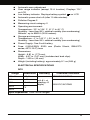
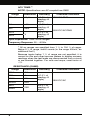
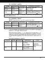
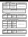
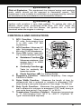
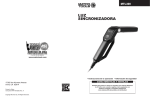
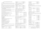
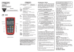
Table of Contents Title Page No. INTRODUCTION .................................................................. SAFETY PRECAUTIONS/WARNINGS .............................. SPECIFICATIONS ............................................................... CONTROLS AND INDICATORS ........................................ TESTING PROCEDURES .................................................. AUXILIARY FUNCTIONS .................................................... BATTERY AND FUSE REPLACEMENT ............................ MAINTENANCE.................................................................... LIMITED ONE YEAR WARRANTY ..................................... SERVICE PROCEDURES .................................................. REPLACEMENT PARTS ..................................................... 1 2 2 3 8 10 17 18 19 22 22 22 INTRODUCTION Congratulations. You have purchased a precision instrument manufactured to the highest quality standards. This Digital Automotive Tester is a general-purpose instrument designed for use in general electronics, home electrical applications, and automotive electrical/electronic systems. This tester is designed to test or measure AC voltage, DC voltage, DC current, AC current, resistance, diodes, continuity, frequency, duty cycle, pulse width, rpm and temperature. Please take the time to read these operating instructions thoroughly and completely. Failure to follow these instructions may result in electrical shock, instrument damage and/or damage to the equipment under test. Always use extreme caution when working on or around electrically operated equipment. SAFETY PRECAUTIONS/ WARNINGS Do not operate this tester before reading this manual in its entirety. The following guidelines must be followed to avoid accidents that can result in electric shock or personal injury. Pay close attention to WARNINGS stamped on the front and rear of the tester’s case. These warnings, as well as all warnings and precautions used through out this manual, must be followed to avoid electric shock and/or personal injury. The RESPONSIBLE PARTY shall be made aware that, if the equipment is used in a manner not specified by the manufacturer, the protection provided by the equipment may be impaired. Before using any of the functions on this tester, verify its proper operation on a known similar function source where the unit value is also known. Take corrective action based on the indicated results. To prevent electrical shock and/or damage to the tester or the equipment under test, observe the following safety precautions: DO NOT apply more than the rated voltage, as marked on the tester, between terminals or between any terminal and earth ground. Use caution when working above 30V AC rms, 42 V peak, or 60 V DC. Such voltages pose a shock hazard. To avoid false readings that could lead to possible electric shock or personal injury, replace the battery as soon as the displays. low battery indicator 2 Always inspect the tester, test leads and any other accessories for damage prior to every use. If any damage is found, do not use tester until repairs are done. Always consider electrical and electronic equipment to be energized (live). Never assume any equipment is de-energized. Do not connect probes to any available (unused) terminal while the meter is connected to a hazardous live circuit. Never ground yourself when taking electrical measurements. Isolate yourself from ground by using dry rubber insulating mats to cover all exposed/grounded metal. Stand on rubber mats and wear dry clothing. Never take resistance measurements on energized (live) electrical or electronic equipment. Use one hand, instead of two, whenever possible to take measurements. If two hands must be used, use extreme caution not to contact any energized conductors with your hands. Be certain test leads are dry and clean. Do not hold the tester when taking measurements. Place the tester on a clean, insulating surface prior to taking any measurement. Don't become part of the circuit. Think safety. Act safely. If working on a vehicle, take the following added precautions: Only work on vehicle in a well ventilated area. Always wear safety eye protection. Avoid moving fan blades or any potentially moving parts. Avoid hot engine parts. Put transmission in "park" (automatic transmission vehicles) or "neutral" (manual transmission vehicles). Set the parking brake. Turn the ignition "off" before connecting or disconnecting any testing equipment. Put blocks on drive wheels. Avoid wearing loose clothing or jewelry when working on a vehicle. Read your vehicle's service manual and follow it's safety procedures. SPECIFICATIONS GENERAL SPECIFICATIONS AND FEATURES 3 3-3/4 digit LCD display (maximum reading of 4000) Range Control: Auto Range Automatic negative (-) polarity indication Automatic zero adjustment Over range indicator (except 15 A function). Displays "OL" on LCD Low battery indicator. Displays battery symbol Automatic power shut off (after 10 idle minutes) Pollution Degree 2 Measuring circuit category II Operating environment: Temperature - 32° to 104° F. (0° C to 40° C) Humidity - Less than 80% relative humidity (non-condensing) Altitude - up to 6562 ft (2000 meters) Storage environment: Temperature - 4° to 140° F (- 20° to 60° C) Humidity - Less than 90% relative humidity (non-condensing) Power Supply: One 9-volt battery Fuse: 0.500A/250V 5X20 mm (Radio Shack, GMA/270 series; #270-1047) fuse on LCD Dimensions: Height - 6.81 in. (173 mm) Width - 6.57 in. (167 mm) (includes test lead clips) Depth - 1.69 in. (43 mm) Weight (including battery): approximately 9.1 oz (260 g) ELECTRICAL SPECIFICATIONS DCV Range Resolution 400mV 100μV 4V 1mV 40V 10mV 400V 600V Accuracy Overload Protection 250V DC/AC RMS ±(0.8% of reading +5 digits) 600V DC/AC RMS 1V Input Impedance: 10MΩ for all ranges. 4 ACV TRMS [1] NOTE: Specifications are AC-coupled true RMS. Range Resolution Accuracy 400mV 100μV ±(1.2% of reading +8 digits) 4V 1mV 40V 10mV ±(0.8% of reading +8 digits) 400V 1V 600V ±(1.2% of reading +8 digits) Overload Protection 250V DC RMS 600V DC/AC RMS Input Impedance: 10MΩ for all ranges. Frequency Response: 50 – 400Hz [1] All ac ranges are specified from 1 % to 100 % of range. Below 5 % of range, add 6 counts (in the range 400mV, an additional 2mV.) Because inputs below 1 % of range are not specified, it is normal for this and other true-rms meters to display nonzero readings when the test leads are disconnected from a circuit or are shorted together. For volts and amps, crest factor of ≤3. RESISTANCE (OHMS) Range 400Ω Resolution 4KΩ 1Ω 40KΩ 10Ω 400KΩ 100Ω 4mΩ 40mΩ 5 Accuracy Overload Protection 0.1Ω 10KΩ ±(1.0% of reading +5 digits) ±(2.0% of reading +5 digits) 250V DC/AC DC CURRENT (AMPS) Range Resolution 40mA 10μA 400mA 100μA *15A 10mA Accuracy Overload Protection ±(1.5% of reading +5 digits) 0.5A/250V fast fuse Input Voltage Drop: <0.2V. ±(2.5% of reading +5 digits) Unfused; 15sec maximum Input Voltage Drop: <0.2V. * A waiting period of at least 15 minutes is necessary between every 15 second testing period. AC CURRENT TRMS [1] NOTE: Specifications are AC-coupled true RMS. Range Resolution 40mA 10μA 400mA 100μA Accuracy ±(2.0% of reading +5 digits) Overload Protection 0.5A/250V fast fuse (Input Voltage Drop: <0.2V. Frequency response: 50 - 400 Hz [1] All ac ranges are specified from 1 % to 100 % of range. Below 5 % of range, add 6 counts. Because inputs below 1 % of range are not specified, it is normal for this and other true-rms meters to display nonzero readings when the test leads are disconnected from a circuit or are shorted together. For volts and amps, crest factor of ≤3. DIODE/CONTINUITY TESTS Function Diode Test Range Resolution 2V 1mV Description Test Current: 1±0.6mA Test Voltage: Approx. 2.8V Continuity Test 400Ω 0.1Ω Note Approx. 120Ω or less, buzzer (beeper) will sound Overload Protection: 250V DC or AC RMS 6 TEMPERATURE Range Accuracy 32°F to 104°F (0°C to 40°C) ±5°F/±3°C -58°F to 392°F (-50°C to 200°C) ±1.5%/±5°F (±1.5%/±3°C) 392°F to 752°F (200°C to 400°C) ±2%/±5°F ±2%/±3°C) Overload Protection 0.5A/250V fast fuse WARNING To avoid fire and/or electrical shock hazards, DO NOT connect the thermocouples to circuits greater than 30 Vrms, 42.4 Vpk or 60 Vdc. FREQUENCY Range 9.999Hz2MHz Resolution 0.001Hz Accuracy ±(0.1% of reading +5 digits) Overload Protection 250V DC or AC RMS Sensitivity: <100kHz: 2V RMS; >100kHZ: 5V RMS DUTY CYCLE/PULSE WIDTH/DWELL Function Range Duty Cycle 0.1 to 99.9% Pulse Width Accuracy 1 to 999 ±(3.0% of ms positive reading ±2 ms) Dwell Angle 1-12 cylinders Overload Protection ±(2.0% of reading +5 digits) 0.5A/250V fast fuse ±(2.0% of reading +5 digits) RPM Range 1-10000 RPM Resolution 1RPM Accuracy ±(2.0% of reading +5 digits) Frequency response: 50 - 400 Hz 7 Overload Protection 0.5A/250V fast fuse WARNING Risk of Explosion. This equipment has internal arcing and sparking parts, which should not be exposed to flammable vapors. This equipment is only suitable for installation in a garage having sufficient air circulation to be considered a non-hazardous location. WARNING Ignition coils produce a very high voltage. To reduce the risks of electric shock when conducting RPM tests, DO NOT touch the uninsulated ends of the test probes, the ignition coil, or the coil terminals when the engine is running. CONTROLS AND INDICATORS 1. DCV Function: Measures DC volts. Auto-ranging from 0 to 600 volts (10 MΩ impedance) 2. ACV Function: Measures AC volts. Auto-ranging from 0 to 600 volts (10 MΩ impedance) 3. Press SEL button (see item 19) to select desired function: Resistance Function : Measures resistance. Auto ranging from 0 to 40MΩ (40,000,000Ω). Continuity Function : Tests for continuity between two points. Diode Function 27 22 21 16 15 14 18 13 12 11 10 9 19 20 1 2 3 4 5 6 7 8 26 25 17 24 23 : For testing diodes. 4. Frequency Function. Measures frequency. One range: 9.999Hz to 2MHz. 5. Pulse Width Function: Measures the length of time (in milliseconds) that a solenoid or actuator is energized (“ON” time) during a one-cycle time period. One range: 1 to 999 ms. 6. Duty Cycle Function: Measures the percentage of time that a solenoid or actuator is energized (“ON” time) during a one-cycle time period. One range: 0.1 to 99.9%. 7. Temperature Function (Celcius): Measures temperature in °C. Auto-ranging from -50°C to +400°C. (Optional “KType” thermocouple required). 8 8. Temperature Function (Fahrenheit): Measures temperature in °F. Auto-ranging from -58°F to +752°F. (Optional “KType” thermocouple required). 9. Press SEL button (see item 19) to select desired function: ACmA Function: Measures AC current in milliamps. One range: 0 to 400 milliamps. DCmA Function: Measures DC current in milliamps. One range: 0 to 400 milliamps. 10. 15A Function: Measures DC current. One range: 15Amps (DC from 0 to 15 amperes). Unfused. 11. Clamp Current Function 12. 13. 14. 15. : Measures AC/DC current; optional Clamp adapter required. DIS RPM Function: Measures RPM on vehicles with Distributorless Ignition Systems (DIS) using an optional inductive pickup. One range: 0 to 10,000 rpm. CON (Conventional) RPM Function: Measures RPM on vehicles with conventional ignition systems using an optional inductive pickup. One range: 0-10,000 rpm. COP RPM Function: Measures RPM on vehicles with “Coil On Plug” ignition systems. One range: 0 to 10,000 rpm. RPM (Tach) Function: Measures RPM. One range: 0 to 10,000 rpm. 16. Dwell Angle Function : Measures dwell angle of breaker points. 17. OFF Function: Turns unit “off” when function is selected. 18. Function/Range Selector Switch: Selects desired function or range. 19. Data HOLD Button: Turns the Data Hold function “on” and “off” (see “AUXILIARY FUNCTIONS” on page 17 for details). Turns the Maximum Value/Minimum Value Record Mode “on” and “off” (see “AUXILIARY FUNCTIONS” on page 17 for details). 21. SEL (Select) Button: Selects the desired function when the Function/Range Selector Switch (item 18) is set to the Resistance/Continuity/Diode position (item 3), ACmA/DCmA position (item 9) or Clamp Current Position (item 11). 22. CYL (Cylinder) Button: Selects the number of cylinders for the vehicle under test when the Function/Range Selector Switch (item 18) is set to the RPM (Tach) function (item 15) or Dwell Angle function (item 16). 23. Volts, OHMS, DIODE, CONTINUITY and FREQUENCY Input Jack. 20. MAX/MIN Record Function: 24. COM Input Jack: Common Input Jack. 9 25. 15A Input Jack. For red test lead probe connection when measuring high DC current (up to 15 amps only). 26. DWELL ANGLE, MS °C, °F, BAT, ACmA/DCmA, CLAMP CURRENT, RPM and COP Input Jack. 27. Liquid Crystal Display (LCD): Displays results of tests or measurements. Preparation and Caution Before Use Inspect the Digital Automotive Tester for damage to the case. Do not use if cracked, distorted, excessively dirty or any abnormal condition exists. Inspect the test leads for damage. Check for cracked insulation, broken or damaged probes, loose or bent probe pins. Do not use if any abnormal condition exists. Set the Function/Range Selector Switch to the proper range BEFORE taking measurements. If the range/function must be switched during a test, ALWAYS remove the test leads from the circuit being measured before switching settings. To avoid possible electric shock, instrument damage, and/or equipment damage when taking voltage or current measurements, DO NOT exceed the maximum value of the selected range. If the tester is used near high noise Radio Frequency (RF) generating equipment (spark plug wires, ignition coils or alternator), the display may become unstable or indicate large errors. If you obtain erratic readings during use, isolate the tester as far away as possible from these components. TESTING PROCEDURES A. AC/DC VOLTAGE MEASUREMENT WARNING To avoid possible electric shock, instrument damage and/or equipment damage, DO NOT attempt to measure voltages ABOVE 600V AC/DC or take measurements if the voltage is unknown. 600V AC/DC between the COM and V jacks is the maximum voltage that this instrument is designed to measure. The "COM" terminal potential should not exceed 300V AC/DC measured to ground. This tester displays AC voltage measurements as True Root Mean Square (RMS) values (the “effective” or “nominal” voltage). The RMS value of an AC voltage is equivalent to the DC voltage that would yield the same power dissipation when applied to a load resistor. True RMS readings are accurate for sinusoidal waves and other wave forms without DC offset ( square waves, triangle waves, staircase waves, etc.). 10 1. Plug the BLACK test lead into "COM" jack of the tester; plug the RED test lead into the "V" jack. NOTE: If alligator clip adapters (not included with tester) are to be used on the test leads, use suitable rated and UL certified alligator clips. 2. Set the tester’s Function/Range Selector Switch to the appropriate DCV or ACV position as desired (see Controls and Indicators, Items 1 and 2). 3. Place the RED test lead onto the positive (+) side of the item being tested and the BLACK test lead onto the negative (-) (across the source/load) side of the item. BE CAREFUL not to touch any energized conductors with any part of your body. 4. Read the results on the display. B. RESISTANCE MEASUREMENT Ω (OHMS) WARNING Resistance measurements must be made on "deenergized" (dead) circuits ONLY. Impressing a voltage across the multimeter's terminals while set to any resistance range may result in electric shock, instrument damage and/or damage to equipment under test. MAKE SURE equipment is completely de-energized before taking any resistance measurements. 1. Plug the RED test lead into the "Ω" jack of the tester; plug the BLACK test lead into the "COM" jack. 2. Set the tester’s Function/Range Selector Switch to the position (see Controls and Indicators, Item 3). 3. Press the SEL button, as necessary, until the (AUTO) icon is shown on the display. NOTE: To obtain accurate readings, disconnect at least one side of the item under test from the circuit or circuit board before measuring resistance. 4. Place the RED test lead onto one side of the item being tested and the BLACK test lead onto the other side of the item. (Polarity does not matter when checking resistance). 5. Read the results on the display. C. DIODE TEST WARNING To avoid electrical shock and/or damage to the multimeter, ensure the power is removed from the circuit before any DIODE testing procedure is conducted. Test diodes on deenergized (dead) circuits only, never on live circuits. 11 NOTE: A diode is a semiconductor device that lets current flow in one direction only. If the diode to be tested is part of a circuit (with other electronic components), you must isolate it from the other components by disconnecting at least one side of it from the circuit before testing. A good diode will show a low voltage drop across its junction (0.5-0.8 volts for a silicon diode or about 0.3V for a germanium diode) when the leads are connected in one polarity and a very high resistance (or open circuit) when the leads are reversed (connected in the opposite polarity). 1. Plug the RED test lead into the jack of the tester; plug the BLACK test lead into the "COM" jack. 2. Set the tester’s Function/Range Selector Switch to the position (see Controls and Indicators, Item 3). 3. Press the SEL button, as necessary, until the icon is shown on the display. 4. Place the RED test lead onto one side of the diode being tested and the BLACK test lead onto the other side. 5. Read the results on the display. 6. Reverse the test leads and again read the results on the display. Compare the two readings. One reading should indicate a voltage drop value; the other reading should indicate an overrange (OL) condition. See previous note. D. CONTINUITY TEST WARNING To avoid electric shock, shut off the power to the test article before testing it for continuity. 1. Plug the RED test lead into the jack of the tester; plug the BLACK test lead into the "COM" jack. 2. Set the tester’s Function/Range Selector Switch to the position (see Controls and Indicators, Item 3). 3. Press the SEL button, as necessary, until the icon is shown on the display. 4. Place the RED Test Lead to one end of the wire or device being tested for continuity and the BLACK Test Lead to the opposite end. 5. Listen to the sound of the beeper and confirm the results by reading the display. NOTE: The beeper will sound only if the continuity of the item under test (resistance between the two test leads) measures less than 120 ohms. 12 E. FREQUENCY MEASUREMENT Frequency is the number of times that an event repeats itself during a one-second time period. Frequency is measured in Hertz (Hz). 1. Plug the RED test lead into the “Hz” jack of the tester; plug the BLACK test lead into the "COM" jack. 2. Set the tester’s Function/Range Selector Switch to the Hz position (see Controls and Indicators, Item 4). 3. Place the RED test lead onto the signal output wire of the sensor or circuit under test and the BLACK test lead onto a good chassis ground (consult the wiring diagram in the vehicle’s Service Manual for proper connections). 4. Read the results on the display. F. PULSE WIDTH MEASUREMENT Pulse Width is the length of time that a solenoid or actuator is energized (“ON” time) during a one-cycle time period. Pulse Width is measured in milliseconds (ms). 1. Plug the RED test lead into the “ms” jack of the tester; plug the BLACK test lead into the "COM" jack. 2. Set the tester’s Function/Range Selector Switch to the ms position (see Controls and Indicators, Item 5). 3. Place the RED test lead onto the signal output wire of the sensor or circuit under test and the BLACK test lead onto a good chassis ground (consult the wiring diagram in the vehicle’s Service Manual for proper connections). 4. Read the results on the display. G. DUTY CYCLE MEASUREMENT Duty Cycle is the percentage of time that a solenoid or actuator is energized (“ON” time) during a one-cycle time period. Duty Cycle is measured in percent (%). 1. Plug the RED test lead into the jack of the tester; plug the BLACK test lead into the "COM" jack. 2. Set the tester’s Function/Range Selector Switch to the DUTY% position (see Controls and Indicators, Item 6). 3. Place the RED test lead onto the signal wire of the sensor or circuit under test and the BLACK test lead onto a good chassis ground (consult the wiring diagram in the vehicle’s Service Manual for proper connections). 4. Read the results on the display. 13 H. TEMPERATURE MEASUREMENT WARNING To avoid fire and/or electrical shock hazards, DO NOT connect the thermocouples to circuits greater than 30 Vrms, 42.4 Vpk or 60 Vdc. NOTE: Temperature measurement requires use of an optional “K-type” thermocouple. 1. Plug the Positive (+) test lead of the “K-type” thermocouple into the °C / °F jack of the tester; plug the Negative (-) test lead into the “15A” jack. 2. Set the tester’s Function/Range Selector Switch to the °C or °F position, as desired (see Controls and Indicators, Items 7 and 8). 3. Read the results on the display. I. AC/DC CURRENT MEASUREMENT (AMPS) WARNING To prevent electrical shock when performing current measurements, follow all steps as indicated below DO NOT skip any steps or take any short cuts. The 15A range is not fused. To avoid current hazard and/or damage to the tester, DO NOT try to take measurements on circuits that have more than 15 amps. DO NOT take more than 10 seconds to take the reading. A waiting period of AT LEAST 15 MINUTES is necessary between every 15 second testing period. This tester displays AC current measurements as True Root Mean Square (RMS) values (the “effective” or “nominal” current). The RMS value of an AC current is equivalent to the DC current that would yield the same power dissipation when applied to a load resistor. True RMS readings are accurate for sinusoidal waves and other AC wave forms without DC offset (square waves, triangle waves, staircase waves, etc.). 1. Plug the RED test lead into the or the "15A" jack of the tester, as applicable; plug the BLACK test lead to the "COM" jack. 2. Set the tester’s Function/Range Selector Switch to the appropriate Amps range position as desired (see Controls and Indicators, Items 9 and 10). Use the SEL button (see Controls and Indicators, item 20) to select DC Amps or AC Amps, as desired. 14 To measure from 0 to 400mA, set the Selector Switch to . To measure from 400mA to 15 Amps DC, set the Selector Switch to the "15A" position. 3. Disconnect the battery, or shut off the power to the circuit being tested. NOTE: To measure current on a particular circuit, you must open up the circuit and connect the test leads in series with the circuit before a reading can be obtained. 4. Disconnect one end of the wire or device, from the circuit where current will be measured. 5. Place the RED test lead on the disconnected wire and place the BLACK test lead at the location from which the wire was disconnected (series connection). 6. Reconnect the battery, or apply power to the circuit being tested. 7. Read the results on the display. CAUTION: After the test is completed, shut the power off to the circuit before removing the test leads and before reconnecting any disconnected wires or devices. NOTE: If the reading obtained is a negative number, reverse the test leads. J. CLAMP CURRENT MEASUREMENT NOTE: Clamp current measurement requires use of an optional Clamp adapter. The optional Clamp adapter has not been evaluated by UL. 1. Plug the RED test lead from the Clamp adapter to the jack of the tester; plug the BLACK test lead into the "COM" jack. 2. Set the tester’s Function/Range Selector Switch to the position (see Controls and Indicators, Item 11). 3. Clamp the Clamp adapter around the wire or cable from the source or load under measurement. 4. Read the results on the display. K. COP RPM AND RPM (TACH) MEASUREMENT WARNING Risk of Explosion. This equipment has internal arcing and sparking parts, which should not be exposed to flammable vapors. This equipment is only suitable for installation in a garage having sufficient air circulation to be considered a nonhazardous location. 15 WARNING Ignition coils produce a very high voltage. To reduce the risk of electric shock when conducting RPM tests, DO NOT touch the uninsulated ends of the test probes, the ignition coil, or the coil terminals when the engine is running. 1. Plug the RED test lead into the "RPM" jack of the tester; plug the BLACK test lead into the "COM" jack. 2. Place the RED test lead onto the “Tachometer Signal port” of the vehicle’s ignition system, or onto the negative (-) side of the ignition coil. Place the BLACK test lead onto a good chassis ground or the negative (-) terminal of the battery. NOTE: If your vehicle is equipped with a COP (Coil On Plug) setting, make the RED system and you are using the test lead connection to the negative (-) side of one of the ignition coils. 3. Set the tester’s Function/Range Selector Switch to the or position, as appropriate (see Controls and Indicators, Items 14 and 15). 4. Press the CYL button, as necessary, until the correct number of cylinders for the vehicle under test is shown on the display. NOTE: Cylinder selection is not applicable to COP (Coil On Plug) systems. 5. Start the engine and read the results on the display. L. CON AND DIS RPM MEASUREMENT NOTE: CON or DIS rpm measurement requires use of an inductive pickup. WARNING Risk of Explosion. This equipment has internal arcing and sparking parts, which should not be exposed to flammable vapors. This equipment is only suitable for installation in a garage having sufficient air circulation to be considered a nonhazardous location. WARNING Ignition coils produce a very high voltage. To reduce the risk of electric shock when conducting RPM tests, DO NOT touch the inductive pickup, the ignition coil, or the coil terminals when the engine is running. 16 Do not apply around or remove from Hazardous Live conductors. 1. Turn the ignition off. DO NOT CONNECT THE INDUCTIVE PICKUP WITH THE ENGINE RUNNING OR WITH THE IGNITION ON. 2. Clamp the inductive pickup clamp around the No. 1 spark plug wire. 3. Plug the RED inductive pickup lead into the "RPM" jack of the tester; plug the BLACK inductive pickup lead into the "COM" jack. 4. Set the tester’s Function/Range Selector Switch to the or position, as appropriate (see Controls and Indicators, Item 12 and 13). NOTE: Cylinder selection is not required when using the inductive pickup. 5. Start the engine and read the results on the display. M. DWELL ANGLE MEASUREMENT NOTE: Turn the vehicle’s engine “off” BEFORE connecting the multimeter for DWELL ANGLE MEASUREMENT. 1. Plug the RED test lead into the jack of the tester; plug the BLACK test lead into the "COM" jack. 2. Place the RED test lead to the “BREAKER POINTS” or “-” terminal of the ignition coil and the BLACK test lead to “GROUND” or the “-” terminal of the battery. 3. Set the tester’s Function/Range Selector Switch to the position (see Controls and Indicators, Item 16). 4. Press the CYL button, as necessary, until the correct number of cylinders for the vehicle under test is shown on the display. 5. Start the engine and read the results on the display. AUXILIARY FUNCTIONS A. DATA HOLD FUNCTION The data HOLD function lets you “lock” the currently displayed value into the display. The value remains on the display until the function is turned “off.” 1. With the desired value shown on the display, press and hold the HOLD button for approximately two seconds, until the HOLD icon shows on the display. The current value is now “locked” in the display. 17 2. Press the HOLD button again to turn the function “off.” The HOLD icon will disappear, and the value will no longer be “locked” in the display. NOTE: The data HOLD function is not available for the DIODE TEST, CONTINUITY TEST or PULSE WIDTH MEASUREMENT. B. MINIMUM/MAXIMUM VALUE FUNCTION The MAX/MIN function records and saves the maximum and/or minimum readings that were achieved during a test. 1. Prepare the tester to perform the desired test as follows (refer to the detailed TESTING PROCEDURES starting on page 10 for the specific connections and settings for the test you wish to perform): Plug the test leads into the appropriate jacks. Set the tester’s Function/Range Selector Switch to the appropriate position. Connect the test leads to the item to be tested. 2. To record Maximum/Minimum readings, press and release the MAX/MIN button to place the tester in MAX/MIN mode. The MAX icon will be visible on the display. Perform the desired test; the maximum reading achieved during the test will be recorded and saved in the tester’s memory. 3. Press the MAX/MIN button again. The MIN icon will be visible on the display. Perform the desired test; the minimum reading achieved during the test will be recorded and saved in the tester’s memory. To scroll between MAX and MIN readings that are stored in the tester’s memory, rapidly press and release the MAX/MIN button. 4. To exit MAX/MIN mode press and hold MAX/MIN button for approximately 2-3 seconds, or until MAX/MIN icons disappear from the display. The tester will save the MAX/MIN readings in memory until the MAX/MIN mode is exited or the tester is turned off. NOTE: MAX/MIN functions is not applicable to the Diode, Continuity or Frequency Functions. BATTERY AND FUSE REPLACEMENT 1. Turn the Digital Automotive Tester “OFF” and remove the test leads. 2. Replace the fuse or battery as necessary: 18 For battery replacement: Remove one screw from the battery compartment cover. Use your finger or a small coin to remove the cover. Remove the battery and replace with one 9-volt battery. For fuse replacement: Remove the three screws (you must remove the meter stand to remove the third screw) on the back of the meter and separate the case. Remove the fuse from the fuse holder and replace with a 0.500A/250V - UL Listed Bussmann, GMA Type (Radio Shack GMA/270 Series: #270-1047) fuse. NOTE: Use a 0.500A/250V, 5x20mm type fuse ONLY Bussmann, GMA Type (Radio Shack #270-1047 or similar). Using an incorrect fuse may result in serious injury and/or damage to the unit. 3. Reassemble the cover/case and secure with the screws. MAINTENANCE 1. No periodic maintenance is required other than the replacement of the battery, the fuse, and visual inspection of the meter. 2. Keep the tester clean and dry. DO NOT use solvent to clean, use a damp (not wet) cloth and fully dry after cleaning. 3. The only replaceable parts are the 9-volt battery, 0.500A/250V fuse (see page 18 for BATTERY AND FUSE REPLACEMENT) and the Test Leads (for Test Leads call service department). 19 20 21 LIMITED ONE YEAR WARRANTY The Manufacturer warrants to the original purchaser that this unit is free of defects in materials and workmanship under normal use and maintenance for a period of one (1) year from the date of original purchase. If the unit fails within the one (1) year period, it will be repaired or replaced, at the Manufacturer’s option, at no charge, when returned prepaid to the Service Center with Proof of Purchase. The sales receipt may be used for this purpose. Installation labor is not covered under this warranty. All replacement parts, whether new or remanufactured, assume as their warranty period only the remaining time of this warranty. This warranty does not apply to damage caused by improper use, accident, abuse, improper voltage, service, fire, flood, lightning, or other acts of God, or if the product was altered or repaired by anyone other than the Manufacturer’s Service Center. The Manufacturer, under no circumstances shall be liable for any consequential damages for breach of any written warranty of this unit. This warranty gives you specific legal rights, and you may also have rights, which vary from state to state. This manual is copyrighted with all rights reserved. No portion of this document may be copied or reproduced by any means without the express written permission of the Manufacturer. THIS WARRANTY IS NOT TRANSFERABLE. For service, send via U.P.S. (if possible) prepaid to Manufacturer. Allow 3-4 weeks for service/repair. SERVICE PROCEDURES If you have any questions, require technical support or information on UPDATES and OPTIONAL ACCESSORIES, please contact your local store, distributor or the Service Center. (877) 336-2826 (33-MATCO) (6:00 AM-6:00 PM, Monday-Saturday PST) Web: www.matcotools.com REPLACEMENT PARTS Soft Pouch Test Leads Thermocouple Inductive Pick-Up Instructions (E/F/S) 85-0007 13-0010 13-0025 3393 93-0259 Rev. A 22