1
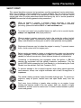
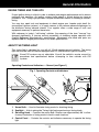
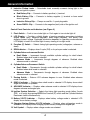
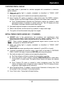
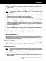
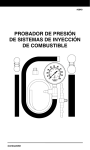
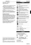
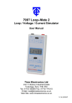
11231 Young River Ave. Fountain Valley, CA 92708 Instruction MRP #93-0299 Copyright © 2010 IEC. All Rights Reserved. © 2010 Table of Contents SAFETY PRECAUTIONS SAFETY FIRST! ........................................................................................ 1 VEHICLE SERVICE MANUALS ...................................................................... 2 GENERAL INFORMATION ENGINE TIMING AND TUNE-UPS........................................................... ABOUT THE TIMING LIGHT .................................................................... OPERATING SPECIFICATIONS ............................................................. 3 3 6 OPERATION APPLICATIONS ....................................................................................... BEFORE YOU BEGIN .............................................................................. ENGINE PREPARATION BEFORE TIMING ........................................... TIMING LIGHT CONNECTION ................................................................ VOLTMETER OPERATION ..................................................................... CHECKING DWELL ANGLE .................................................................... INITIAL TIMING CHECK (USING NO. 1 CYLINDER) ............................. ADVANCE/RETARD TIMING CONTROL CHECKS ................................ TIMING ADJUSTMENT ............................................................................ TROUBLESHOOTING ............................................................................. 7 7 7 8 8 9 9 10 11 11 MAINTENANCE CLEANING THE INDUCTIVE PICKUP CLIP ........................................... REPLACING THE INDUCTIVE PICKUP LEADS .................................... 13 13 WARRANTY AND SERVICE LIMITED ONE YEAR WARRANTY .......................................................... SERVICE PROCEDURES ....................................................................... REPLACEMENT PARTS ......................................................................... 17 17 17 i Safety Precautions SAFETY FIRST! This manual describes common test procedures used by experienced service technicians. Many test procedures require precautions to avoid accidents that can result in personal injury, and/or damage to your vehicle or test equipment. Always read your vehicle's service manual and follow its safety precautions before and during any test or service procedure. ALWAYS observe the following general safety precautions: When an engine is running, it produces carbon monoxide, a toxic and poisonous gas. To prevent serious injury or death from carbon monoxide poisoning, operate the vehicle ONLY in a well-ventilated area. To protect your eyes from propelled objects as well as hot or caustic liquids, always wear approved safety eye protection. When an engine is running, many parts (such as the coolant fan, pulleys, fan belt etc.) turn at high speed. To avoid serious injury, always be aware of moving parts. Keep a safe distance from these parts as well as other potentially moving objects. Engine parts become very hot when the engine is running. To prevent severe burns, avoid contact with hot engine parts. P RND L Before starting an engine for testing or trouble-shooting, make sure the parking brake is engaged. Put the transmission in park (for automatic transmission) or neutral (for manual transmission). Block the drive wheels with suitable blocks. Connecting or disconnecting test equipment when the ignition is ON can damage test equipment and the vehicle's electronic components. Turn the ignition OFF before connecting the Code Reader to or disconnecting the Code Reader from the vehicle’s Data Link Connector (DLC). To prevent damage to the on-board computer when taking vehicle electrical measurements, always use a digital multimeter with at least 10 megOhms of impedance. The vehicle's battery produces highly flammable hydrogen gas. To prevent an explosion, keep all sparks, heated items and open flames away from the battery. Don't wear loose clothing or jewelry when working on an engine. Loose clothing can become caught in the fan, pulleys, belts, etc. Jewelry is highly conductive, and can cause a severe burn if it makes contact between a power source and ground. 1 Vehicle Service Manuals Always refer to the manufacturer’s service manual for your vehicle before performing any test or repair procedures. Contact your local car dealership, auto parts store or bookstore for availability of these manuals. The following companies publish valuable repair manuals: Haynes Publications 861 Lawrence Drive Newbury Park, California 91320 Phone: 800-442-9637 Web: www.haynes.com Mitchell 1 14145 Danielson Street Poway, California 92064 Phone: 888-724-6742 Web: www.m1products.com Motor Publications 5600 Crooks Road, Suite 200 Troy, Michigan 48098 Phone: 800-426-6867 Web: www.motor.com FACTORY SOURCES Ford, GM, Chrysler, Honda, Isuzu, Hyundai and Subaru Service Manuals Helm Inc. 14310 Hamilton Avenue Highland Park, Michigan 48203 Phone: 800-782-4356 Web: www.helminc.com IMPORTANT! Timing procedures vary from vehicle to vehicle. ALWAYS refer to the Vehicle Emission Label or service manual for the vehicle to obtain the proper timing procedures, specifications, and location of timing marks. OBSERVE ALL SAFETY PRECAUTIONS WHENEVER WORKING ON A VEHICLE. 2 General Information ENGINE TIMING AND TUNE-UPS Proper ignition timing is critical in order to achieve peak engine performance and to ensure maximum fuel economy. An ignition system timing check is critical during any tune-up procedure. Your Timing Light provides a simple and efficient means of checking a vehicle’s timing. You may also need tools and equipment to check engine rpm, breaker point dwell (for conventional ignition systems), or to apply vacuum to the vacuum advance diaphragm on the distributor during advance checks. Your supplier offers a wide range of tools and equipment necessary to perform these tasks. With reference to today's "self-tuning" vehicles, the meaning of the term "tune-up" has changed significantly. A tune-up consists essentially of checking engine operation with Original Equipment Manufacturer's specifications. Adjustments are made and parts are replaced ONLY if engine performance is not within specifications. ABOUT THE TIMING LIGHT This timing light is designed for use with all 12-volt negative-ground vehicles. The timing light may also be used on vehicles equipped with DIS (distributorless ignition systems). Some DIS systems are not adjustable. Consult the vehicle's service manual for procedures and specifications before at-tempting to time vehicles with DIS systems. Operating Controls and Indicators — General (see Figure 1) Fig. 1. Operating Controls and Indicators 4 5 3 1 2 1. Xenon Bulb — Used to illuminate timing marks for checking timing. 2. Spotlight — Aids in aiming the Timing Light before performing a timing check. 3. Swiveling Head — Contains the xenon bulb. Rotates over approximately 90° to allow for easy illumination of timing marks in hard to reach locations. 4. Control Panel — Contains the controls and indicators necessary to operate the timing light. 3 General Information 5. Inductive Pickup Leads — Detachable leads assembly connects timing light to the battery and ignition system: Red Battery Clip — Connects to battery positive (+) terminal. Black Battery Clip — Connects to battery negative (-) terminal or bare metal chassis ground. Inductive Pickup Clip — Clamps around No. 1 spark plug cable. Green DWELL Clip — Connects to the negative (tach) side of the ignition coil. Control Panel Controls and Indicators (see Figure 2) 1. Flash Switch — Push to turn strobe light on. Push again to turn strobe light off. 2. LCD Display — Provides a digital display of engine operating parameters including engine speed (rpm), advance (degrees), dwell angle (degrees), and battery and charging system voltage. Displayed information depends on operating mode selected. LCD display is backlit in soft blue light for easy viewing in low-light areas. 3. Function (F) Switch — Selects timing light operating mode (voltage/rpm, advance or dwell). 4. RPM Indicator — Displays when 2-cycle (DIS) or 4-cycle rpm mode is selected. 5. Cylinder/Advance Increment Switch Dwell Mode — Increments through available cylinder settings for dwell check. Enabled when dwell mode is selected. Advance Mode — Increments through degrees of advance. Enabled when advance mode is selected. 6. Cylinder/Advance Decrement Switch Dwell Mode — Decrements through available cylinder settings for dwell check. Enabled when dwell mode is selected. Advance Mode — Decrements through degrees of advance. Enabled when advance mode is selected. 7. Zeroing Switch — Returns LCD advance degrees to zero. Enabled when advance mode is selected. 8. DWELL Indicator — Displays when dwell mode is selected. LCD display shows dwell angle and number of cylinders. 9. ADVANCE Indicator — Displays when advance mode is selected. LCD display shows degrees advance and engine rpm. 10. Ignition System Selection — Selects the timing light operating mode (either 2-cycle (DIS) or 4-cycle) by pressing BOTH the Function (F) switch and the Cylinder/Advance Decrement switch simultaneously. 11. Battery VOLTS Indicator — Displays when battery voltage mode is selected. LCD display shows battery voltage. 12. Charging System Battery VOLTS Indicator — Displays when voltage/rpm mode is selected. LCD display shows charging system battery voltage and engine rpm. 13. Volt Symbol — Displays when voltage modes are selected. 4 General Information 2 5 7 6 10 3 10 1 14 15 19 16 13 4 9 11 BATTERY VOLTAGE MODE 15 ADVANCE MODE 16 17 18 13 8 12 4 DWELL MODE VOLTAGE/RPM MODE Fig. 2. Control Panel Controls and Indicators 5 General Information 14. Battery Symbol — Displays when battery voltage mode is selected. 15. Flash Symbol — Blinks when strobe light is operating. 16. Ignition Mode Symbol — Displays ignition system selected. 17. Cylinder Symbol — Displays when dwell mode is selected. 18. Dwell Angle Symbol — Displays when dwell mode is selected. 19. Advance Degree Symbol — Displays when advance mode is selected. OPERATING SPECIFICATIONS Power Requirements: 10 to 16 volts DC Operating Temperature: 32 to 122°F (0 to 50°C) Tachometer Range: 240 to 9,990 RPM Timing Advance Range: 0 to +90° 6 Operation APPLICATIONS This timing light is designed for use on most late model import or domestic vehicles equipped with conventional or electronic ignition systems, or with DIS (distributorless ignition systems). BEFORE YOU BEGIN Make a thorough check before starting any test procedure and fix any known mechanical problems before performing any test. Loose or damaged hoses, wiring, or electrical connectors are often responsible for poor engine performance. Refer to the vehicle’s service manual for proper connection of vacuum hoses, electrical wiring, and wiring harness connectors. Check the following areas: All fluid levels Spark plugs and spark plug wires Air cleaner Vacuum hoses Belts Electrical wiring Electrical connectors ENGINE PREPARATION BEFORE TIMING Always prepare the engine for timing before performing a timing check. Refer to the Vehicle Emission Control Label or service manual for timing procedures and specifications for the vehicle. The Vehicle Emission Control Label is located under the hood in the engine compartment. The label is typically located on the underside of the hood, on a fender well or valve cover, or near the hood latch. Fig. 3 Typical Timing Marks 14 BTDC 10 6 0 10 20 30 0 TDC 6 ATDC 20 As a minimum, make the following preparations before timing: 16 12 8 4 1. Locate the timing mark and reference pointer. The timing mark and pointer are usually located on the crankshaft pulley or vibration damper (on the front of the engine) or on the flywheel (between the engine and transmission). Refer to Figure 3. BTDC ATDC 10 T 10 Make sure the timing mark and pointer are clean and clearly visible. Chalk the marks if necessary. 0 4 8 12 16 2. Make sure all spark plugs are in good condition and properly gapped. 7 20 10 T 0 BTDC Operation 3. Start and run the engine until it reaches its normal operating temperature. TURN THE ENGINE OFF BEFORE CONNECTING TIMING LIGHT. If applicable, check and adjust dwell to manufacturer's specifications. TIMING LIGHT CONNECTION WARNING: Always keep hands, timing light, lead wires and clips away from moving engine parts and hot surfaces. DO NOT SMOKE. 1. Turn ignition off. DO NOT CONNECT TIMING LIGHT WITH IGNITION ON OR ENGINE RUNNING. 2. Clamp inductive pickup clip around No. 1 spark plug wire (arrow points toward spark plug). See Figure 4. DO NOT ALLOW THE INDUCTIVE PICKUP CLIP TO CONTACT THE EXHAUST MANIFOLD OR OTHER ENGINE PARTS. These parts become EXTREMELY hot while the engine is running, and will damage the inductive pickup clip. Fig. 4. Inductive Pickup Clip Connection INDUCTIVE PICKUP #1 SPARK PLUG WIRE ENGINE 3. Connect the green DWELL clip to the negative (tach) side of the ignition coil (if applicable). 4. Connect battery clips to battery: Connect RED clip to battery positive (+) terminal. Connect BLACK clip to battery negative (-) terminal or chassis ground. 5. Attach pickup leads into bottom of timing light handle. The spotlight will turn on automatically. VOLTMETER OPERATION Make sure timing light is properly connected as described in TIMING LIGHT CONNECTION. ALWAYS check battery and charging system voltage before performing timing check to ensure reliable results. 1. With timing light connected and engine off, timing light is in battery voltage mode; the Battery VOLTS indicator, Volts symbol and Battery symbol will display. The LCD display will show battery voltage. 2. When the engine is started, the timing light enters the voltage/rpm mode; the Charging System Battery VOLTS indicator, Volts symbol and Ignition Mode symbol (either 2cycle (DIS) or 4-cycle) will display. The LCD display will show charging system voltage and engine rpm. 8 Operation CHECKING DWELL ANGLE Dwell angle check is performed for vehicles equipped with conventional or electronic ignition systems. Make sure timing light is properly connected as described in TIMING LIGHT CONNECTION. 1. Start and run engine until it reaches normal operating temperature. 2. Press Function (F) switch as needed to select dwell mode. The DWELL Indicator, Cylinder Symbol, and Dwell Angle Symbol will display when dwell mode is selected. Press Cylinder/Advance Increment and Decrement switches as needed to select appropriate number of cylinders for vehicle under test. The LCD display will show the number of cylinders selected and the dwell angle. 3. Note dwell angle and compare to manufacturer's specifications. 4. Refer to the vehicle's service manual for procedures to adjust dwell angle. 5. Turn ignition off and disconnect timing light from engine. INITIAL TIMING CHECK (USING NO. 1 CYLINDER) ALWAYS refer to the manufacturer's test procedures and specifications when performing timing check. Timing procedures vary from vehicle to vehicle. Refer to the Vehicle Emission Control Label or service manual for the vehicle under test. NOTE: Some vehicles equipped with computerized engine control systems may be designated as "NON-ADJUSTABLE". Make sure timing light is properly connected as described in TIMING LIGHT CONNECTION. MAKE SURE the proper operating mode is selected (2- cycle (DIS) or 4-cycle). If vehicle is equipped with distributor points, check dwell as described in CHECKING DWELL ANGLE, and adjust if necessary BEFORE performing timing check. 1. Start and run engine until it reaches normal operating temperature. The Flash Indicator will blink to indicate the timing light is operating. Press both ignition system selection switches SIMULTANEOUSLY to select either 2-cycle (DIS) or 4-cycle mode. The Ignition Mode Symbol will display the selected mode. Press Function (F) switch as needed to select voltage/rpm mode. The RPM Indicator will display when voltage/rpm mode is selected. The LCD display will show engine rpm. Adjust engine rpm as necessary. 2. Adjust timing light barrel, as needed, to ensure proper illumination of timing marks. Use the spotlight to aid in aiming the Timing Light properly. 3. Press Flash switch. Timing Light will begin flashing. 9 Operation 4. Note the position of the timing mark in relation to the reference pointer. See Figure 5. Refer to the vehicle's service manual to check and adjust timing. OBSERVE ALL SAFETY PRECAUTIONS. Fig. 5. Reading Timing Marks 5. Press Flash switch. Timing Light will stop flashing. 6. Turn ignition off and disconnect timing light from engine. 7. If disconnected, reconnect vacuum line to distributor. ADVANCE/RETARD TIMING CONTROL CHECKS Advance and retard timing controls ensure that ignition occurs at the proper time during the compression stroke. These controls include mechanical advance, vacuum advance, vacuum retard, electronic advance, electronic retard, and electronic advance/retard. Depending on make and model, a vehicle may be equipped with a single timing control device, or two or more devices may be used in combination. NOTE: Advance and retard timing test procedures vary widely from vehicle to vehicle. The following paragraphs provide general test procedures for checking mechanical advance, mechanical/vacuum advance, and vacuum retard. ALWAYS make sure initial timing and dwell are correct before checking advance/retard timing. ALWAYS refer to the service manual for the vehicle under test to obtain the proper timing procedures and specifications. OBSERVE ALL SAFETY PRECAUTIONS. Centrifugal/Mechanical Advance Make sure timing light is properly connected as described in TIMING LIGHT CONNECTION. Make sure initial timing is correct. If necessary, prepare engine for advance timing check as directed by manufacturer's instructions. 1. With timing light directed at timing marks, note position of rotating timing mark in relation to reference pointer. Reading should indicate initial timing in accordance with manufacturer's specifications. 2. Adjust engine speed to the specified RPM for advance test. 3. Press Function (F) switch as needed to select advance mode. The ADVANCE indicator and Advance Degree symbol will display when advance mode is selected. The LCD display will show "0" degrees advance and engine rpm. 4. With timing light directed at timing marks, press Cylinder/Advance Increment switch as needed to realign timing marks to initial timing or as instructed by manufacturer's specifications. Note degrees advance on LCD display and compare with manufacturer's specifications. 5. Turn off ignition and disconnect timing light from engine. 10 Operation Vacuum Advance Make sure timing light is properly connected as described in TIMING LIGHT CONNECTION. Make sure initial timing is correct. If necessary, prepare engine for advance timing check as directed by manufacturer's instructions. NOTE: A vacuum pump equipped with a vacuum gauge is needed to check vacuum advance. 1. With engine off, disconnect vacuum hose from distributor's vacuum advance port; plug vacuum hose. 2. Connect vacuum pump to distributor's vacuum advance port. 3. Start and run engine until it reaches normal operating temperature. 4. Press Function (F) switch as needed to select advance mode. The ADVANCE indicator and Advance Degree symbol will display when advance mode is selected. The LCD display will show "0" degrees advance and engine rpm. 5. With timing light directed at timing marks, note position of rotating timing mark in relation to reference pointer. Reading should indicate initial timing in accordance with manufacturer's specifications. 6. Using vacuum pump, apply specified amount of vacuum to distributor's vacuum port. 7. With timing light directed at timing marks, press Cylinder/Advance Increment switch as needed to realign timing marks to initial timing. Note degrees advance on LCD display and compare with manufacturer's specifications. 8. Turn off ignition and disconnect timing light from engine. Unplug and reconnect vacuum hose to distributor's vacuum port. Electronic Advance/Retard Refer to manufacturer's instructions for procedures to check electronic advance/retard. For some systems, it may be necessary to set the timing light's advance display to "0" and to read timing from the vehicle's timing marks. TIMING ADJUSTMENT Refer to the vehicle’s service manual for procedures to adjust timing. DO NOT ATTEMPT TO ADJUST TIMING WITHOUT MANUFACTURER’S SPECIFICATIONS. TROUBLESHOOTING NOTE: If the timing light readout becomes inoperative or locks up during use, disconnect and reconnect the timing light's positive battery clamp from the battery to reset the unit. If the timing light fails to operate, make the following checks: 1. Make sure the battery clips are firmly connected to the battery terminals. 2. Make sure the battery clip polarity is correct (red clip to positive terminal, black clip to negative terminal). 11 Operation 3. Make sure the upper and lower ferrite cores of the inductive pickup clip are clean. Clean the inductive pickup clip if necessary (refer to MAINTENANCE). 4. Make sure the inductive pickup clip is properly connected to the No. 1 spark plug cable. 5. Make sure the No. 1 spark plug is working properly: Connect the inductive pickup clip to another spark plug cable. If the timing light flashes, service the No. 1 spark plug before continuing. Low spark plug voltage or a faulty spark plug wire may cause the Timing Light to operate erratically. Try moving the inductive pickup clip to a new location on the plug wire to improve operation. Some ignition systems and/or specialty spark plug wires (solid core wires, racing wires, off-road wires) radiate above normal Electro-Magnetic Interference (EMI) and Radio Frequency Interference (RFI) which can cause improper operation of testing equipment. Contact the manufacturers of these parts for instructions on how to use an inductive pickup with their systems. 12 Maintenance CLEANING THE INDUCTIVE PICKUP CLIP Dirt or grease on the inside surfaces of the inductive pickup clip can result in erratic flashing or poor operation of the timing light. Periodically clean the contact surfaces inside the inductive pickup clip by wiping with a soft cloth. See Figure 6. Fig. 6. Cleaning the Inductive Pickup Clip REPLACING THE INDUCTIVE PICKUP LEADS The timing light is equipped with detachable leads which can be disconnected from the timing light for easy storage after use. If the test leads or clips become damaged, a replacement set can be obtained from your dealer or directly from the service center. 13 CLEAN CONTACT SURFACES Notes 14 Notes 15 Notes 16 Warranty and Service LIMITED ONE YEAR WARRANTY The Manufacturer warrants to the original purchaser that this unit is free of defects in materials and workmanship under normal use and maintenance for a period of one (1) year from the date of original purchase. If the unit fails within the one (1) year period, it will be repaired or replaced, at the Manufacturer’s option, at no charge, when returned prepaid to the Service Center with Proof of Purchase. The sales receipt may be used for this purpose. Installation labor is not covered under this warranty. All replacement parts, whether new or remanufactured, assume as their warranty period only the remaining time of this warranty. This warranty does not apply to damage caused by improper use, accident, abuse, improper voltage, service, fire, flood, lightning, or other acts of God, or if the product was altered or repaired by anyone other than the Manufacturer’s Service Center. The Manufacturer, under no circumstances shall be liable for any consequential damages for breach of any written warranty of this unit. This warranty gives you specific legal rights, and you may also have rights, which vary from state to state. This manual is copyrighted with all rights reserved. No portion of this document may be copied or reproduced by any means without the express written permission of the Manufacturer. THIS WARRANTY IS NOT TRANSFERABLE. For service, send via U.P.S. (if possible) prepaid to Manufacturer. Allow 3-4 weeks for service/repair. SERVICE PROCEDURES If you have any questions, require technical support or information on UPDATES and OPTIONAL ACCESSORIES, please contact your local store, distributor or the Service Center. (877) 336-2826 (33-MATCO) (6:00 AM-6:00 PM, Monday-Saturday PST) Web: www.matcotools.com REPLACEMENT PARTS Pro Inductive Pickup PN 5596 17 11231 Young River Ave. Fountain Valley, CA 92708 Instruction MRP #93-0299 Copyright © 2010 IEC. All Rights Reserved. © 2010