1
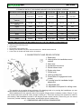
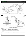
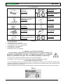
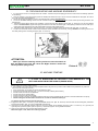
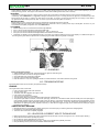
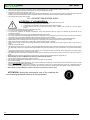
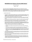
S.p.A.
INSTRUCTIONS AND MAINTENANCE MANUAL MC 2300 “REVERSO”
25/11/2002
SpA
MC 2300
INTRODUCTION Thank you for selecting a BENASSI SPA machine.
This manual contains all the information and necessary data for the preservation and proper use of the machine.
The better you know your agricultural machine, the safer will be your work; therefore we suggest you to read carefully
and understand this “INSTRUCTIONS AND MAINTENANCE” manual before starting to work.
You will find important use notice relating to the use of the machine, which will help you to fully exploit its technical
characteristics. You will also find useful information concerning carefulness and maintenance, important for your safety, guide to
use and lasting preservation of your machine’s value.
BENASSI SPA, in line with a policy of continuous technical improvement, reserves the right to change mechanical
parts, finishing and accessories. Data concerning dimensions, weights and performances are intended with DIN rules
allowances.
Pictures, descriptions and technical features are without obligation.
SERVICE AND WARRANTY BENASSI SPA put at the customers’ disposal its technical service to solve any problems concerning use and
maintenance of the machines and points out that they all have 12 months (a year) warranty after purchase as far as defective
material is concerned. In cases of difficulty please contact your retailer.
Please use BENASSI SPA products, original spare-parts and accessories; BENASSI SPA disclaims all responsibility for
any alteration or improper application.
BENASSI SPA shall not be liable for the application to its machines of accessories made by third persons, without previous
authorisation.
TABLE OF CONTENTS IN THIS MANUAL: 1)
2)
Machine specifications
Technical features of the engines mounted on the
different versions
3) Characteristics and drives captions
4) Dimensions and overall dimensions
5) Packing and transport
6) Accessories
7) Symbols and decalcomania's
8) Machine identification
9) Use of the machine
10) Control description
11)
12)
13)
14)
15)
16)
17)
18)
19)
20)
21)
Tools mounting and machine reversibility
Machine starting
Start of the work
End of the work
Use of the machine-Milling unit reversibility
Maintenance and machine lubrication
Garaging
Troubleshooting
Rules for a correct use of the machine
Accident-prevention rules
CE Declaration of the machine
1 –TECHNICAL FEATURES OF THE MACHINE ENGINE
4 strokes – 5 HP / 5,5 HP.
CLUTCH
Cone lined in oil bath.
GEARBOX
with gears in oil bath – 1 fwd. speed +1 rev. with wheel disengaging.
P.T.O
power mower version: 980 R.p.m. with sense of rotation Left.
engine driven cultivator version: 640 R.p.m. with sense of rotation Right.
HANDLEBAR
adjustable in height and sideways – assembled on vibration dampers, 180° reversible.
WHEELS
tractor gummed 3.50.6 - 13.500.6 or iron.
TRACK
from cm. 38,5 with wheels 3.50.6 at cm. 43 with wheels 13.500.6.
TOOLS
power mower version:
cutterbar cm 92 with eccentric motion, brush, snow turbine.
engine driven cultivator version:
cutter cm 40-50, plough, lister.
SPEED
AT
PEAK RPM
2
power mower version: km/hr 2,3
engine driven cultivator version: km/hr 1,5
SpA
MC 2300
2 TECHNICAL DATA OF THE ENGINES MOUNTED ON THE DIFFERENT VERSIONS TECHNICAL FEATURES
MC 2300 D
MC 2300 H
MC 2300 HS
MC 2300K
MC 2300I
Engine
YANMAR
HONDA
HONDA
KAMA
INTERMOTORL
L 48 AE DI
GX 160
GC 160
KG 160
LGA 226
Weight Cultivator
version
Kg. 81
Kg. 70
Kg. 66,5
Kg. 69
Kg. 72
Weight Lawn mower
version
Kg. 85
Kg. 74
Kg. 70,5
Kg. 73
Kg. 76
Cycle
diesel
Otto (OHV)
Otto
Otto
Otto
kW - (HP)
3,48 (4,7)
4 - (5,5)
3,7 - (5)
3,6 (4,9)
4,4 (6,0)
Displacement
211 cc.
163 cc.
160 cc.
163cc.
220cc.
RPM
3.600
3.600
3.600
3.600
3.600
Consumption/HR
Kg./h 0,90
Kg./h 1.20
Kg./h. 1,15
Kg./h 1,2
Kg./h 1,8
Filter
Oil Bath
Oil Bath
Dry air filter
Oil Bath
Dry air filter
ENGINES WHICH EQUIPS THE MACHINES HAVE ALL THE FOLLOWING CHARACTERISTICS:
•
•
•
•
•
Starting with autowinding rope.
Dry air-filter.
Oil quantity in the engine 0,6 l.
Working with standard car petrol 90/100 octanes ron. Diesel fuel MC 2300 D.
Cone clutch in oil bath with lined hub for all versions.
3‐ CHARACTERISTICS AND DRIVES CAPTIONS 1. Spark plug
2. Locking lever for handlebar mount
rotation
3. Gear lever
4. Accelerator hand lever
5. Wheel release lever
6. Engine stop lever
7. Clutch lever
8. Locking pushbutton
9. Power take-off engagement lever
(cutter)
10. Locking lever for handlebar height
adjustment
11. Adjustable spur
12. Adjustable hood panel for milling cutter
The machine is an engine driven cultivator. By changing tools or by turning the handlebars you can
obtain different configurations for different uses as well.
With handlebars on the opposite side of the engine (Engine driven cultivator version, Picture 2) you
can mount back tools (such as cutter, ploughs, listers etc.). This main version of the machine is used for
soil working. With handlebars turned on the engine (Power mower version, Picture 2a) you can mount
front tools ( central cutterbar, lawn mower, snow turbine, brush, leveller, etc.).
4 – DIMENSIONS AND OVERALL DIMENSIONS 3
SpA
MC 2300
Engine driven cultivator version
Power mower version
5 – PACKING AND TRANSPORT The machine is normally delivered packed, without accessories, in carton boxes having the following dimensions and overall
dimensions:
Machine packing :
- WIDTH: 47 cm.- LENGTH cm: 71 - HEIGHT cm. 58
Mowing unit packing :
- WIDTH: 38 cm.- LENGTH cm: 40 - HEIGHT cm. 50
Accessories are normally delivered separately from the machine; with or without packing.
To take the machine out of the packing and prepare it for work, proceed in the following way:
a) Open and take the machine out of the packing, with a second person’s help; mount the wheels and lock them with the
suitable pin.
b) Unscrew the hand lever (Ref. 10 Picture 1) and mount the handlebars at the desired height.
c) Fill the engine with oil SAE 20-40 up to the mark on the oil dipstick, about 0,6 l. ( SAE 20 for low temperatures, SAE 40 for
warm climates).
d) Assemble the accessories (see Picture 3 accessories).
4
SpA
MC 2300
6 ‐ACCESSORIES Wheels torque 3.50.6
Cod. 97063300
Mowing unit
cm. 38-48
Cod. 94761600
Wheels torque 13.500.6
Cod. 97063400
Cutting unit cm. 92 with special
cutterbar and spare blade
Cod. 94564600
Plough
Cod. 91062500
Snow turbine cm.50
single-stage
Cod. 97561200
Lister with arm
Cod. 91063500
Single-blade lawn mower cm.52
Cod. 96660600
Front-end leveller
Cod. 97561100
Weight for mowing bar (only for
version with YANMAR engine)
Cod. 98061400
Kit for wheels torque 3.50.8
Cod. 97063500
Picture 3
ALSO AVAILABLE:
•
•
•
•
•
•
Transfer wheel unit cod. 97063000.
Iron wheel torque Ø 370 x 100 cod. 97063100.
Iron wheel torque Ø 370 x 50 cod. 97063200.
Front ballast Kg. 10 cod. 98061200.
Coupler head cod. 91063400.
Wheel spacer torque cod. 94961800.
7 ‐SYMBOLS and DECALCOMANIA'S On the machine, equipment and this manual there are symbols, writings and
directions accompanied by this sign: it suggests the presence of a potential
danger. Pay attention when you see it, read carefully and keep to what it says.
Do not remove or make the decalcomania's present on the machine unreadable.
It is obligatory to clean them when dirty and immediately change them if detached or damaged.
8 –MACHINE IDENTIFICATION The machine identifies itself with the type and part number of the gearbox. The part number of the engine is stamped (when
it exists) by the producer on the plate of the engine itself or on the engine case. Identification data of the machine are carried
forward on a plate placed on the machine.
Report the label’s data of the machine on the label’s facsimile in order to have them always close at hand when necessary.
Fig. 4-
5
SpA
MC 2300
9 –USE OF THE MACHINE The machine illustrated in this manual has been made only to be used in agriculture and mostly for the ground milling.
Any use out of this agricultural one is considered an improper one.
The producer disclaims all responsibility for damages or injuries resulting from the improper use of the machine.
The respect of the working conditions, maintenance and repairs established by BENASSI SPA, according to the rules, are
also part of the machine use.
The machine can be used, subjected to maintenance and repaired only by someone who has previously read this manual
and has been informed about its eventual dangers.
Any alterations made on the machine excludes responsibility byside of the BENASSI SPA for the resulting damages.
10 – DRIVES DESCRIPTION A) CLUTCH CONTROL LEVER is used to disengage the engine from the transmission, it must be operated every time you operate levers and
before stopping the machine. The lever is connected to the ENGINE-STOP (Ref. ”B” - Picture 5); To ignite the machine engage and lock the
clutch together with the lowered engine-stop, with the pushbutton outside the lever (Ref. “A” Picture 6). If the lever is not locked, the engine
will not start since it is earthed. To unlock the clutch lever it is sufficient to pull lightly the lever upwards and the locking will be automatically
released.
B) ENGINE STOP LEVER the main function of this safety device is to stop immediately the engine in the moment that one takes away his
hands from the handlebars and to lock the clutch lever in engaged position (disengagement of the engine from the driveline organs ) in
order to prevent sudden starting of the machine during the ignition phase of the engine . If the clutch lever is not locked with the button
inside the engine-stop in engaged position, the engine, being connected to earth, will not start. The engine-stop is also used to switch off
the engine at the end of the work.
C) ACCELERATOR HAND-LEVER permits to increase or decrease the engine R.P.M. (power). By pushing it downwards clockwise you
increase R.P.M.; by pushing it upwards counterclockwise you decrease them.
D) WHEEL DISENGAGE LEVER is used to disengage the wheels from transmission. This lever helps to move the machine when switched
off.
E) REVERSE LEVER is used to reverse the machine motion; by pulling the lever in the cultivator version towards the driving place, the
machine goes forwards, by pushing it forward the machine goes backwards. The speed in the cultivator version is slower than in the lawn
mower version. A safety device does not allow to engage the reverse gear when the milling cutter is in motion. See Ref. ”A” Picture 8.
Before engaging the reverse gear disengage the milling cutter.
F) P.T.O LEVER is used to engage the power take-off to the different tools. By pushing the lever forward, in the lawn mower version, you
disengage the power take-off, by pulling it towards the driving place you engage it. In the cultivator version, by pushing forward you engage
the power take-off and by pulling the lever towards the driving place you disengage it.
G) HAND LEVER FOR HANDLEBAR LOCKING is used to adjust the handlebars in the most comfortable position to work. Once you have
obtained the desired position, you have to tighten the hand lever.
H) HAND LEVER FOR STEERING COLUMN LOCKING is used to regulate sideways the handle and to 180° reverse the handle itself. By
unscrewing the hand lever you release the steering column, which can pivot; once you have obtained the desired position tighten strongly.
To 180° reverse the steering column take off the reverse levers and P.T.O and put them on again. The hand lever is pawl operated (see
hand lever for handlebar locking ).
¾
¾
¾
6
FILLING AND VENT OIL CAP (Ref. ”A” - Picture 7).
DISCHARGE GEARBOX OIL CAP. (Ref. ”A” Picture 14)
LEVEL OIL SCREW (Ref. “B” Picture 7)
SpA
MC 2300
11‐ TOOLS MOUNTING AND MACHINE REVERSIBILITY ¾
It is very easy to mount or to change tools to the machine. Tools are all quick coupling type and don’t need screws or fastening spanners
for the locking.
¾ Tools are coupled in the machine body (male and female) and locked with a pin. The pin must be locked with the lever (Ref. “B” Picture
8) in order to avoid its disengagement.
¾ Assure that the tool part (male) to couple in the machine body is always well lubricated.
¾ To turn the handlebar steering column from the Cultivator version (back tools) to the Power mower version (front tools) proceed in the
following way:
1) Take off the speed selector levers PTO completely, unscrew the hand lever steering column (Ref. “H” Picture 5), turn 180° the steering
column counterclockwise, tighten thoroughly the hand lever and insert the levers again, not forgetting to lock them with its cotter pins,
making them pass through the two holes with fairlead on the left of the handle support.
2) Take off the safety locking rod for reverse gear, (Ref. “A” Picture 8), slipping off the two special cotter pins, (Ref. “C” Picture 8).
¾ To pass from the Power mower version to the Cultivator version proceed in the same way, turning clockwise the steering column. Put
the safety locking rod for reverse gear again, (Ref. “A” Picture 8).
ATTENTION:
When you turn the steering column you have to turn the wheels as
well: the Right to the Left, the Left to the Right. Picture 9 shows the
correct position (see groove)
Picture 9
12 MACHINE STARTING BEFORE USING THE MACHINE MAKE SURE YOU LEARNT HOW TO STOP
IT; IN CASE OF BREAKDOWN OR NECESSITY TAKE IMMEDIATELY THE
LEFT HAND AWAY FROM THE HANDLE (ENGINE STOP).
Before starting the machine always control :
¾ the oil levels in the engine with the proper oil dipstick and in the gear box by means of the suitable screw (make this only when the
machine is new and every 50 hours );
¾ that in the air-filter (if in oil bath) oil reaches the reference notch;
¾ that tyres have the right pressure ( Atm. 1,3) and are correctly oriented (see Picture 9 );
¾ that all screws and nuts are well fastened;
¾ that all levers are in neutral position;
¾ that the clutch lever has some freeplay;
¾ that there is fuel in the tank, the refuelling must be done with a funnel complete of filter in order to avoid the introduction of impurity;
¾ Before starting the machine make sure there are not walls or obstacles behind you.
To start the machine proceed in the following way:
1) Engage the clutch, (Ref. “A” Picture 5), lower the ENGINE STOP lever, (Ref. “B” Picture 5) and lock both with the rectangular pushbutton
inside the left handle, (Ref. “A” Picture 6) (ENGINE STOP device).
2) Close the air to the carburettor (starter), open the fuel cock, position the accelerator hand lever, (Ref. “C” Picture 5), at ½ gas and pull
vigorously the rope of the ignition, (Ref.”15” picture 1). When the engine is running release the starter.
3) Warm up the engine for some minutes before starting to work.
When the engine is new, make some running in period.
7
SpA
MC 2300
13 – START OF THE WORK Accurately inspect the work area, removing foreign objects ( iron wires, stones, sticks, glasses etc.), since they could cause dangerous and
sudden reactions of the machine.
Engage the clutch, the ENGINE STOP pushbutton will release itself, then put into gear and power take-off, giving little clutch-touches if it
does not immediately engage.
Accelerate opportunely the engine and release the clutch to start working.
ATTENTION If the power take-off is engaged, you cannot engage the reverse gear. In this case disengage the power
take-off and then engage the reverse gear. It is impossible to insert the milling cutter when the reverse gear is engaged.
14 – END OF THE WORK Once you have ended your work, to stop the engine close the fuel cock and push the STOP ENGINE button or release the ENGINE STOP
lever. (Ref. ”B” Picture 5).
15 USE OF THE MACHINE – MILLING UNIT REVERSIBILITY The principal uses of the machine are:
Cultivator version (See Picture 2);
Power mower version (See Picture 2a).
IMPORTANT :
Before doing the operations described below, switch off the engine.
The milling unit (Picture 11) can be mounted so that the mowing rotation corresponds to the advancing wheel rotation or
contrary to it. See the dart indication on the mowing unit side.
To change the rotation take out the hood panel for milling cutter unscrewing the two bolts (Ref. “A” Picture 10) and the bolt
(Ref. B Picture10).
Slip the milling transmission unit off by pulling the lever (Ref. B Picture 8), remove the spur (Ref. A Picture 11), taking off the
bolt (Ref. A Picture 11) and mount it again upside-down. Then mount the hood panel for milling cutter again on the
transmission unit upside-down making all the inverse process .
The milling cutter hood panel can enable, through two adjustable sides (Ref. “B” and “C” Picture 11) two working width, cm.
40 and 50.
In the narrower version, the milling blades of the external cutters have to be screwed and turned inwards (Ref. ”D” Picture11).
16 MAINTENANCE AND LUBRICATION A good maintenance and a perfect lubrication are both necessary operations to keep your machine perfectly efficient. The machine is
normally delivered packed and without engine oil, as it is indicated on the note applied to the engine.
ENGINE
Please follow the specific “ENGINE USE AND MAINTENANCE” booklet provided with the machine for instructions, use and maintenance of
the engine.
It is a good rule to control the oil level every 5 hours of work and to change it every 50 hours. Use oil SAE 40 in summer and SAE 20 in
winter. The first oil change must be done after 10 hours of work.
8
SpA
MC 2300
Control that the air-filter is clean, if the filter is in oil bath control the level every 8-10 hours of work or even more frequently if you are
working in dusty grounds. Use engine oil to restore the oil level; before refilling the oil tank, wash it carefully.
GEAR BOX
Control the oil level every 50 hours of work by taking out the cap on the gearbox case (the machine must be in the horizontal position).
If necessary, add oil SAE 80-90. It is suggested to change oil at least once a year . To empty the oil in the gear box, unscrew the cap of the
inferior part of the box (Ref. “A” Picture 14), take out the oil cap (Ref. “A” picture 7) to allow the oil flowing out more easily. Put the inferior
cap again and fill with oil though the cap (Ref. ”A” Picture 7) up to the screw level (Ref. “B” Picture 7).
MILLING CUTTER
Before starting to work, control that all screws are well fastened, especially those of the mill hoes.
Control the oil level of the milling cutter transmission unit every 100 hours of work , by taking out the cap on the lid (Ref. “E” Picture 11). Oil
must fill almost completely the gearbox case. Use SAE 80-90 oil.
CUTTERBAR
¾
¾
¾
¾
¾
Before starting to work, control that all screws are tight fastened.
Every 4 hours of work lubricate the inside of the blade head.
Every 10 hours of work lubricate the eccentric ferrule - (Ref. “A” Picture 12).
Every 20 hours of work lubricate the linkage between the cutterbar and the machine.
Periodically is needed to control bladeholders (Ref. “B” Picture 12) so that the blade has not too much freeplay or is fastened too tight. If
the cutting of the grass after the adjustments is not satisfying, the blade needs to be grinded or changed.
17 ‐GARAGING Before garaging the machine:
¾ Wash it carefully with Diesel fuel, change the engine oil, gear box and milling unit .
¾ Empty the fuel tank and wash or change the air-filter.
¾ Oil and lubricate every joints and mechanism.
¾ Change or repair eventual damaged parts.
¾ Park the machine in a dry room, putting its wheels on wooden boards or, even better, lifted from the ground.
18 ‐ TROUBLESHOOTING Eventual troubles which can be solved by the operator (worker) :
ENGINE :
The engine doesn’t start; control that:
¾
¾
¾
¾
¾
¾
¾
Fuel in the tank reaches half of the tank itself .
The fuel cock is open.
The starter must be engaged if the engine is cold.
Fuel arrives to the carburettor.
The vent cap on the tank is not clogged.
The carburettor castings are open; otherwise clean them with compressed air.
The ignition spark works: to test this, unscrew the spark plug, reconnect it to the electric cable, lean the metallic part of the spark plug to
mass (working cylinder) and turn the engine pulley as for the starting . If the ignition spark does not spark among the electrodes, control
the joints of the electric cable. Otherwise change the spark plug with another one . If even this attempt fails, the breakdown has to be
attributed to the lighting set (points, capacitor, coils etc.). In this case we suggest to apply to the nearest service relating the engine
mounted on the machine.
GEARS DO NOT ENGAGE :
¾ Regulate the clutch by unscrewing the register screw (Ref. “B” Picture 6) till you obtain a good clutch disengagement.
¾ Pay attention: do not eliminate totally the freeplay.
¾ The clutch wire must not be completely engaged.
19 – RULES FOR A CORRECT USE OF THE MACHINE ¾
¾
¾
¾
¾
Make a good running in period to the engine and the machine (for at least 10 hours do not get over 70 % of the engine capacity ).
Always use the clutch before operating any levers.
Do not leave the clutch disengaged for a long time.
Never force the speed selector levers and PTO, if they do not engage leave gradually the clutch.
Keep the steering column joint and the handlebar cleaned and oiled.
9
SpA
MC 2300
¾
¾
¾
¾
Never force the engine; when smoke comes out from the exhausting pipe, it means that the engine is under stress.
Do not work for long periods of time at full speed, in particular during warm periods.
Periodically control the tyre pressure ( Atm. 1,3)
During the mounting of the different tools do not damage the dowels (Ref. ”D” Picture 8) and the splines, control that screws and the
fastening spine of the tools are well locked, especially screws of the mill hoes and the fastening screws of the cutterbar.
¾ Do not leave the machine under the rain.
20 – ACCIDENT‐PREVENTION RULES ATTENTION, IT IS DANGEROUS:
¾
¾
¾
¾
¾
¾
¾
¾
¾
¾
¾
¾
¾
¾
¾
¾
¾
¾
¾
¾
¾
¾
¾
¾
¾
To leave the engine running in closed rooms; exhaust gases are highly toxic.
To refuel with the engine running or overheated.
To accelerate going to reverse; the engine must be at minimum speed.
To make tests, to clean and to repair tools (milling cutter, cutterbar, lawn mower etc.) with the engine
running.
To touch the just switched off engine (some parts may burn).
To move with the cutterbar without protection.
To execute the operations of transport, maintenance, repair and lubrication with the engine not switched off and without all the
protections mounted.
On means of transport the machine must be well fastened with proper locking.
The cutter protections must be adjusted according to the depth of the work , so that the part of the tool which cuts the ground remains
uncovered; never make hoeing operations without the back hood panel on the machine.
Keep always efficient the safety disposals ( above all the automatic engine stop ) and the protections of the rotating elements.
Before starting to work make sure there are not persons or obstacles in the machine range of action inferior to 5 meters.
Wear proper shoes and clothes, do not wear large or fluttering clothes (scarf or foulard).
Never work in sloping grounds without having assured the machine stability. Attention! Do not work in grounds with a more than 50 %
slope.
Keep the fuel in proper tanks.
The refuelling must be done in airy places, with the engine switched off and cold. During this operation do not smoke, if the fuel comes
out (especially petrol) dry the wet parts and if possible blow away with compressed air, move the machine in a dry place before starting
it.
To move the machine from a work ground to an another one or during the reverse manoeuvres, before starting the work again always
disengage the power take-off to stop the moving organs.
The waste disposal of lubricators and batteries must be done in conformity with the rules in force in the country where the machine is
used.
Before leaving the machine, disengage the power take-off, stop the engine and take away the plug spark cap.
Read carefully the Use and Maintenance booklet provided with the machine.
The use of the machine is forbidden to persons under 16 .
The operator is responsible for the damages, since he is the driver of the machine.
Dry the petrol leakage.
Refill the tank with the engine switched off. The refuelling and/or the fuel pouring off must always be done outside, far from fire or heat
sources. Do not smoke during this operation.
Before starting to use the engine driven cultivator, it is necessary to learn how to rapidly switch the engine off, to familiarise with the
drives and to learn how to properly use the machine. Do not make the engine run where outlets with carbonic oxide could accumulate.
We disclaim all responsibility for incidents caused by non-observance of these rules.
ATTENTION: during the continuative use of the machine the
use of hearing protection devices is recommended.
10
SpA
MC 2300
21 ‐ CE DECLARATION CONFORMITY OF THE MACHINE 40010 San Matteo della Decima BO Italy Via Lampedusa n°1
We declare under our responsibility that the machine is conformity with the essential safety and health protection in accordance
with Directive 98/37/EC, to the requirements of Directive 2000/14/EC applicable to it.
TYPE ENGINE DRIVEN CULTIVATOR
MODEL MC 2300
For verification of the conformity with the above-mentioned Directives reference has been made to following specifications: UNI
EN 709; EN-ISO 12100-1 e EN-ISO 12100-2
MANAGING DIRECTOR
S. Matteo della Decima li 25/11/2002
RESULT AND TESTS
Sound power level LwA= 90 - 102 dB (A)
Test conditions: height 1,6 Mt handlebar centre
Handlebar vibration :11,3 -19,6 m/sec2
INSTRUCTIONS FOR THE CORRECT MOUNTING OF THE LEVERS
CORRECT
WRONG
11
SpA
MC 2300
S.p.A.
VIA LAMPEDUSA 1
40010 S. MATTEO DELLA DECIMA (BO) - ITALY
TEL. 0039/051/82.05.34 TELEFAX 0039/051/682.61.64
Web: www.benassi.eu e-mail: [email protected]
Retailer stamp
12