1
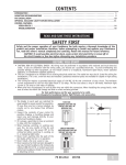
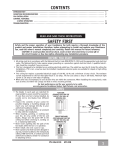
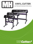
CONTENTS INTRODUCTION . . . . . . . . . . . . . . . . . . . . . . . . . . . . . . . . . . . . . . . . . . . . . . . . . . . . . . . . . . . . . . . . . . . . . . 1 MOUNTING RECOMMENDATIONS. . . . . . . . . . . . . . . . . . . . . . . . . . . . . . . . . . . . . . . . . . . . . . . . . . . . . . . . . . 2 FAN INSTALLATION . . . . . . . . . . . . . . . . . . . . . . . . . . . . . . . . . . . . . . . . . . . . . . . . . . . . . . . . . . . . . . . . . . . 3 CONTROL FEATURES: VERSA•TOUCH OPERATION . . . . . . . . . . . . . . . . . . . . . . . . . . . . . . . . . . . . . . . . . . . . . . . . . . . . . . . . . .10 TROUBLESHOOTING . . . . . . . . . . . . . . . . . . . . . . . . . . . . . . . . . . . . . . . . . . . . . . . . . . . . . . . . . . . . . . . . . . .12 PRODUCT SPECIFICATIONS. . . . . . . . . . . . . . . . . . . . . . . . . . . . . . . . . . . . . . . . . . . . . . . . . . . . . . . . . . . . . . .13 READ AND SAVE THESE INSTRUCTIONS SAFETY FIRST Safety and the proper operation of your Casablanca fan both require a thorough knowledge of the product and proper installation; therefore, before attempting to install and operate your Casablanca fan, read this owner’s manual completely and carefully. Retain this manual for future reference. CAUTION: To avoid possible electrical shock, make certain that electricity is turned off at the circuit breaker or fuse box before attempting any installation procedure. BEFORE YOU START • All wiring must be in accordance with the National Electric Code ANSI/NFPA 70-1993 and the appropriate local electrical codes. The National Electric Code requires proper grounding as a precaution against electrical shock. A qualified electrician should be consulted if you are unsure. • This fan is designed to be installed on an existing electrical outlet box. The outlet box must be UL Listed for ceiling fan installations, if it is not, a new box must be installed. Casablanca extension poles are available for sloped or high ceiling installations. • This ceiling fan requires a grounded electrical supply of 120 VAC, 60 Hz and a minimum 15 amp circuit. The maximum current requirement for the fan with light fixture is 1.48 amps Star / 1.28 amps Starlet. The fan uses about .85 amps (102 watts) Star / .65 amps (78 watts) Starlet. Maximum light current is .63 amps or 75 watts of lighting. • Where wire nuts are employed, be sure all bare wires are within the connectors. When installing the canopy hatch, make sure all wires are within the canopy and that no wires are being pinched. For best performance and for your warranty to be valid, use only genuine Casablanca blades, light fixtures, and accessories. SAFE USE • The blades in each pack are matched for equal • • • • • • weight to assure smooth fan operation. If more than one fan is being installed, be careful not to mix blades from different cartons. Inspect the contents of your carton for possible shipping or handling damage and report any such damage directly to your authorized Casablanca dealer. It is always a good idea to have an assistant to help with the installation. When cleaning, painting, or working near your fan, be very careful of the fan and blades. Always turn the power OFF to the ceiling fan before servicing it, working on it, or replacing light bulbs. Never insert anything into the path of the fan blades while the fan is in operation. Never install a fan over a pool or spa. Never operate a fan that has been damaged in any way. Contact Casablanca Fan Company by calling 1-888-227-2178), or contact your local authorized Casablanca dealer for assistance in obtaining service. FUSE BOX (REMOVE FUSE FOR THE CIRCUIT YOU WILL BE WORKING ON) 18″ 70″ CIRCUIT BREAKER (TRIP BREAKER FOR THE CIRCUIT YOU WILL BE WORKING ON) PN C2843001 AT0209 84″ 1 MOUNTING RECOMMENDATIONS Before mounting your Casablanca fan, read the following helpful recommendations. The location of the fan, air circulation, and fan size are all important factors to consider before installation. Location Ceiling fans have practical uses in almost every room in your home. We suggest you follow these mounting recommendations as you decide where to install your Casablanca fan. • For safety reasons, the fan blades must be a minimum of 7′ above the floor. • Do not locate the fan in a doorway or above a swinging door. • In any installation, the tips of the blades must be at least 18″ from the wall in order to provide sufficient clearance for the blades. • In bedrooms, fans work best when mounted above the foot of the bed. • Over pool tables, be sure to provide plenty of clearance to avoid damage from pool cues. • In low ceiling locations, our optional low ceiling adapter (LCS) - available at extra cost can be used to gain 31/2″ (not applicable to Stealth, Venus and Silhouette series). • In kitchens be sure to allow for open cupboard doors to clear the fan blades. • Do not install a fan close to, or over, a pool or spa. High humidity combined with corrosive gases will destroy the finish and warp the blades. Fan Size Variable fan speed capability permits the use of a full-size 52″ fan even in smaller rooms. For very large rooms, two fans may be needed. SLOPED CEILING INSTALLATIONS Suggested Extension Pole Lengths Ceiling Height Pole Length 8′ Standard 8′ 6″ Standard 9′ 6″ 9′ 6″ 12″ 10′ 12″ 11′ 18″ 12′ 24″ 13′ 36″ 14′ 48″ When to Use Extension Poles For best performance and best appearance, an extension pole should be used with your Casablanca fan when installing on high (cathedral) ceilings or sloped ceilings. Casablanca offers standard poles in increments of 6″ up to 5′. See your Authorized Casablanca Dealer for details. NOTE: Fan may wobble or vibrate if pole length is not long enough and inside blade is too close to downslope or side wall. Extending pole length will usually solve problem. Calculation of 32° Use the tear-off Ceiling Angle Template card inserted in this manual. It provides you with a simple ‘go’ or ‘no-go’ for installing your fan on a sloped ceiling. 2 EXTENSION POLE 32° MAXIMUM HANG-TRU® ANGLE 32º BLADES MUST BE A MINIMUM OF 7′ ABOVE THE FLOOR 7′ MINIMUM EXAMPLE 1 This slope is less than 32˚. It is OK to install your fan. EXAMPLE 2 This slope is 32˚. This is the maximum slope that will allow the fan to hang straight down. It is OK to install your fan. EXAMPLE 3 This slope is more than 32˚. Your fan will not hang straight down, an adapter is necessary. Contact your local Authorized Casablanca Dealer in regards to purchasing a “Slope Ceiling Adapter.” Star™ / Starlet ™ INSTALLATION INSTRUCTIONS Unpacking: Before assembling and installing your ceiling fan, remove all parts from the shipping cartons and check them against the parts listed here. Before discarding packaging material, be certain that all parts have been removed. SETUP Setup: Remove the fan body from the box and place the body of the fan on top of a cloth on a flat surface. This will protect the fan body from being scratched during assembly. PERMA•LOCK™ HARDWARE LOCKING BOLT (MOTOR COUPLING) DOWNROD & BALL ASSEMBLY FAN PREPARATION IMPORTANT SAFETY INFORMATION! BEFORE STARTING THE INSTALLATION OF YOUR CEILING FAN, INSTALL THE THREADED DOWNROD INTO THE MOTOR COUPLING AND LOCK THE ASSEMBLY Prepare for fan installation as follows: Step A. Route the wires from the motor through the Perma•Lock™ downrod and ball assembly. Tip: The downrod has a tapered thread that is designed to lock completely when correctly installed. Step B. Thread the downrod into the motor coupling and turn it clockwise until it stops turning, ensuring that the pole has bottomed out. Step C. Securely tighten the locking bolt to ensure safe operation of your fan. MOTOR WIRES TAPERED THREAD GROUND WIRE DOWNROD & BALL ASSEMBLY LOCKING BOLT MOTOR COUPLING CAUTION: Failure to fully lock in the downrod before securely tightening the locking bolt may cause the fan to separate from the downrod during normal operation! 3 CEILING HARDWARE 1″ x 8-32 ROUND HEAD SCREWS (2) WIRE NUT (4) LAG SCREW AND WASHER (1) CROSSBAR MOUNTING BRACKET FLAT WASHER (2) GETTING STARTED Installing a New Ceiling Fixture Outlet Box If you do not have an existing fixture located where you wish to place your Casablanca fan, an approved ceiling fixture outlet box must be installed and wired. Warning: To reduce the risk of fire, electrical shock, or personal injury, mount to outlet box marked acceptable for ceiling fan support using the mounting hardware provided with the outlet box. Using Existing Ceiling Fixture Outlet Box After turning the power OFF at its source (either circuit breaker or fuse box), lower the old fixture and disconnect the wiring. Check the ceiling fixture outlet box to be sure that it is marked ‘Approved for ceiling fan mounting’. If it is not, a new box must be installed. CROSSBAR MOUNTING BRACKET INSTALLATION Proceed with installation as follows: Step 1. Place the wires from the ceiling outlet box to one side of the crossbar mounting bracket. Attach the bracket, with ground wire and ridges down, to the ceiling fixture outlet box with the mounting hardware included with the outlet box. Tighten the screws firmly by hand only, being careful not to bend the bracket by over tightening. CAUTION: To reduce the risk of personal injury, use only the mounting hardware provided with the approved outlet box to install the crossbar mounting bracket. JOIST CEILING WIRING GREEN GROUND WIRE CEILING FIXTURE OUTLET BOX (CEILING FAN RATED) CROSSBAR MOUNTING BRACKET (RIDGE SIDE DOWN) WASHERS (2) 1” X 8-32 ROUND-HEAD SCREWS (2) LAG SCREW AND WASHER (1) 4 Star™ / Starlet ™ CANOPY HARDWARE CANOPY HATCH CANOPY SCREW (4) CANOPY LOCK WASHER (4) CANOPY PHILLIPS SCREWDRIVER CANOPY INSTALLATION Step 2. Attach the canopy to the crossbar mounting bracket with three of the 8-32 x 21/4″ long canopy screws and canopy lock washers. Tighten the screw firmly by hand only. Note: On sloped ceilings, align the canopy opening towards the top or room peak. CROSSBAR MOUNTING BRACKET CANOPY CANOPY SCREW CANOPY LOCK WASHER 5 BLADE HARDWARE BLADE SCREW (4 PER BLADE) RUBBER WASHER (4 PER BLADE) BLADE (3) METAL WASHER (4 PER BLADE) BLADE INSTALLATION Step 3. Assemble the blades to the motor using the blade screws, rubber washers and metal washers. BLADE SCREW & WASHERS Hand tighten firmly. BLADE SCREW METAL WASHER RUBBER WASHER 6 Star™ / Starlet ™ HANGING THE FAN Step 4. To hang the fan body in the canopy, hold the fan body firmly and insert the ball into the canopy opening. Check that no wires were pinched. Rotate the fan body until the slot in the nylon ball fits into the pin opposite the canopy opening. BALL SLOT PIN CANOPY ELECTRICAL CONNECTIONS Step 5a. Attach the fan wires to the ceiling fixture outlet box wiring by twisting the bare ends of the wires together and then securing with a wire nut. Test that the connection is secure by pulling on the wire nut. Connect in this order: Step 5b. Wiring Connections • GREEN leads from mounting plate and fan to GROUND conductor of power source. Secure with wire nut. • WHITE wire from fan to white NEUTRAL wire in ceiling fixture outlet box. Secure with wire nut. • BLACK power wire from fan to BLACK power wire in ceiling outlet box. Secure with wire nut. 2 BLACK WIRES 2 WHITE WIRES 3 GREEN WIRES WIRE NUT CANOPY HATCH INSTALLATION Step 6. Tuck the wires into the canopy with the wire nuts pointed upwards, so that the WHITE and BLACK wires are on opposite sides of the canopy and all wires are clear of the canopy opening. Step 7. Install canopy hatch with the last canopy screw and lock washer. To do this, tilt the fan body away from the hatch opening. Tighten the screws firmly by hand only. Step 8. Straighten the fan, then check to ensure that there is no movement between the canopy and ceiling or Hang-Tru ball and top support shaft. CANOPY HATCH LOCK WASHER CANOPY CANOPY SCREW TILT THE FAN TO INSTALL LAST CANOPY SCREW 7 ATTACHING THE LIGHT FIXTURE Step 9a. Before getting started, remove the rubberband from the plug connector. STEPS 9a - 9c Step 9b. Install two of the three light adapter screws into the light adapter plate. Thread the plug connector through the hole in the center of the light adapter plate. Step 9c. Align the two key slot holes with the two screws and rotate the light adapter plate clockwise. Install the third light adapter screw and securely tighten all three screws. Tighten the screws firmly by hand only. LIGHT ADAPTER SCREWS LIGHT ADAPTER PLATE Step 9d. Connect the light fixture plug to the plug from the bottom of the fan. STEPS 9d LIGHT FIXTURE STEPS 9e Step 9e. Align the light fixture to the three screw holes on the light adapter plate using the light fixture screws, then attach the light fixture to the fan. LIGHT FIXTURE SCREWS 8 Star™ / Starlet ™ INSTALLING THE HALOGEN BULB IMPORTANT! When installing the halogen bulb, carefully cut off the end of the plastic sleeve the bulb comes in and hold the bulb by the plastic sleeve to screw it into the socket. Step 10. Screw the 75-watt halogen bulb into the socket. Do not touch the glass bulb with your fingers it is extremely important that the glass be clean. If it is accidentally touched, or dirty, clean carefully with a tissue. A dirty glass will cause the bulb to fail almost immediately. HALOGEN BULB NOTE: In compliance with US Federal Energy Regulations, this ceiling fan contains a device that restricts the light fixture to a maximum of 190 watts. Exceeding that limit or the marked limit on this product may result in a fire hazard or improper operation. LIGHT SOCKET HALOGEN BULB INSTALLING THE GLASS SHADE Step 11. Position the indentations in the outer rim of the glass shade so that they line up with the tabs on the inside surface of the fan light fixture rim. Carefully lift the glass shade up inside the light fixture as far as it will go. Rotate the shade in a clockwise direction until it is held tightly in place by the three tabs. TAB TIP: At first the shade is a very loose fit in the fixture and can be ‘wiggled’ a little from side to side. It is a great help when rotating the glass shade to ‘wiggle’ it at the same time. GLASS SHADE GLASS SHADE INDENTATION 9 VERSA•TOUCH2™ CONTROL INSTALLATION VERSA•TOUCH2™ HARDWARE (not to scale) 12v Battery W-72 Control Wood Screw 1" (2) Drywall Anchor 6-32 (2) W-72 Control Holder Screw 6-32 X 3/8" (2) Screw 6-32 X 1" (2) CONTROL BRACKET INSTALLATION SAFETY FIRST: To reduce the risk of electrical shock, this fan must be installed with an isolating wall control/ switch. CAUTION! Do not use with wall dimmer. WARNING: To reduce the risk of fire or electric shock, do not use this fan with any solid state speed control device. Use only the control provided with this fan. Step 12. Follow instructions for the type of transmitter control bracket you will be using. STANDARD TOGGLE SWITCH INNER MOUNTING HOLES SWITCH COVER PLATE ROCKER LIGHT SWITCH OUTER MOUNTING HOLES CONTROL BRACKET CONTROL BRACKET SWITCH COVER PLATE Standard Light Switch Rocker Light Switch Step A. Remove the two screws holding the switch cover plate. Do not remove the cover plate. Step A. Break off the two tabs by pushing outward. Step B. Orient the control bracket as shown and line up the two inner mounting holes with those on the switch. Step C. Insert and tighten the screws using the provided screwdriver. Wall Installation Step A. Locate a 2x4 wall stud in a convenient location. Step B. Orient the control bracket as shown over the 2x4 stud. Step C. Insert the 1" wood screws in either the inner or outer mounting holes and tighten using the provided screwdriver. 10 Step B. Remove the two screws holding the switch cover plate. Do not remove the cover plate. Step C. Orient the control bracket as shown and line up the two inner mounting holes with those on the switch. Step D. Insert and tighten the screws using the provided screwdriver. NOTE: The wall anchors and 6-32 x 1" screws may be used in situations where mounting to a stud is not possible. Use the inner mounting holes. After securing the anchor, discard the anchor’s pointed screws and use the 6-32 decor ovalhead screws supplied. ANCHOR PANHEAD SCREW WOOD SCREW 1" DRYWALL ANCHOR DECOR OVALHEAD SCREW 6-32 X 1" ® REMOTE OPERATION Fan Control To start the fan. Press the selected speed button to run the fan at the desired speed. LOW=Low speed MED=Medium speed HIGH=High speed To turn off the fan, press the FAN OFF button. Airflow Direction To reverse the airflow, press the REVERSE button. REVERSE operates at any speed whether the fan is on or off. The fan returns to its set speed after reversing. Light Control Turn the light on or off independently from the fan by pressing the LIGHT button. If you press the button for more than 0.7 seconds, it becomes a dimmer. The light varies from “bright" to “dim” over approximately 8 seconds. If you continue to hold the LIGHT button, this sequence will reverse when the light reaches its brightest or dimmest level. Release the button when the desired level is reached. Send Signal LED LIGHT MED HIGH LOW FAN OFF REVERSE Memory Feature The last light fuction and fan speed will resume when power is turned back on. Auto Resume Quick (pressing less than 0.7 seconds) on/off operation of the LIGHT button maintains the desired brightness level set previously. CHANGING TRANSMITTER FREQUENCY SETTING Note: All fans leave the factory set to “00000.” VERSA•TOUCH 2 CONTROL (BACK) You will only have to change the dip switch settings in the remote if you are using more than one fan in the same area and want to control them separately. Step 1. At the circuit breaker or fuse box, turn the power off for the fan you want to change. Step 2. Open the battery door of the Versa•Touch control and remove the batteries. Step 3. Change the dip switch settings, assuring that they are different from the previously installed Versa•Touch fan. Step 4. Re-install the batteries and the battery door on the control. Step 5. At the circuit breaker or fuse box, turn the power back on for the fan whose frequency you are changing. Step 6. Within 20 seconds of restoring power, push the HIGH, MED, and LOW buttons (in that order). DIP SWITCH SET TO “10000” DIP SWITCH SET TO “01001” WARNING! Note: You may want to label your controls to assure you do not mix them up. If the fan is not functioning after installation: Do not turn the power off at the circuit breaker, then back on, for the previously installed Versa•Touch2 fan(s), as you may inadvertently change the frequency settings for it as well. 2 Step 1. Check to make sure that batteries are installed correctly in the control. 3 Step 2. Turn the power off to the fan (from the circuit breaker) for at least 5 seconds. Step 3. Turn the power back on (at the circuit breaker) and push the HIGH, MED, and LOW buttons–in that order–within 20 seconds. Step 4. The fan should now function properly. CIRCUIT BREAKER OR FUSE BOX 1 PRESS IN THIS ORDER TO SET NEW FREQUENCY: 1. HIGH 2. MED 3. LOW 11 TROUBLESHOOTING TIPS Please refer to this troubleshooting guide before requesting service or contacting your dealer for assistance. PROBLEM POSSIBLE REMEDIES Fan will not start • Check the main circuit fuses, circuit breakers, and wall switch position. Check all wire connections. Make sure the power is turned off during this inspection. • The 9-pin connector is not making good contact. Check the 9-pin connector in the receiver mounted in the switch housing • The battery is weak. Install a fresh battery. • The fan receiver is defective. Replace fan receiver. • Check the frequency setting: Turn the power off at the circuit breaker, only for the fan that is not functioning. Check that the jumper switches match in both the receiver and the transmitter. Fan wobbles or shakes excessively • Be sure the canopy pin is set properly into the slot on the ball. • The hanger bracket and/or ceiling outlet are attached too loosely. Make sure the hanger bracket is attached tightly to the ceiling outlet box and the downrod assembly is secured firmly. • Check that the bladeholders have not been bent during installation and the blades are balanced. • The downrod is attached to downrod base too loosely. Make sure all the screws are securely tightened. Fan is noisy during operation • Check and tighten the light fixture retaining screws, glass shade screws, and/or lightbulb(s). • Tighten the canopy screws and mounting plate assembly. Make sure the wire nuts inside the canopy and switch housing are not touching the metal parts and that they have not fallen off the wire splices. Tighten as necessary. • Tighten the blade holders to the flywheel (or direct drive motor) and the blades to the bladeholder screws. • Make sure all screws in the motor housing are snug but not overly tight. Fan does not run on low speed • If fan is new, it may need to be “broken in.” Run at high speed for several days. Battery life is short • Replace with alkaline batteries. Light works, but fan does not work • The fan wires are not connected properly. Fan and light run only on full speed • The fan receiver is defective. Replace fan receiver. Fan is missing one speed • The fan receiver is defective. Replace fan receiver. Fan does not change speed, but light works • The fan receiver is defective. Replace fan receiver. Reverse does not work • The fan receiver is defective. Replace fan receiver. Fan starts working by itself • There is frequency interference. Change frequency. Fan operates only when transmitter is close • Check that antenna wire is not touching metal plate. Fan works, but light does not dim • The fan receiver is defective. Replace fan receiver. Fan works, but light does not work • The fan receiver is defective. Replace fan receiver. • A lightbulb is defective. Replace lightbulb. • The light socket is broken. Replace socket. NOTE: In compliance with US Federal Energy Regulations, this ceiling fan contains a device that restricts the light fixture to a maximum of 190 watts. Exceeding that limit or the marked limit on this product may result in a fire hazard or improper operation. 12 Star™ / Starlet ™ PRODUCT SPECIFICATIONS Model Name: Model Number: Star™ C28GXXM Dimensions: NOTE: Dimension B light fixture includes and glass. A =11.8" B =14.35" C = 3" D =8.09" E =7.7" Model Name: Model Number: Starlet™ C29GXXM Dimensions: NOTE: Dimension B light fixture includes and glass. A =11.7" B =14.35" C = 3" D =8.09" E =7.7" Weight: Weight: 27 lbs. 20 lbs. Motor: Blade Span: Blade Iron Pitch: No. of Blades: Technology: Lightbulb: 172mm x 20mm Direct Drive™ 52" 15° 3 Versa•Touch2® W-72 (1) 75-watt halogen Airflow: Electricity Use*: Airflow Efficiency*: Motor: Blade Span: Blade Iron Pitch: No. of Blades: Technology: Lightbulb: 5,640 cfm 66 watts 84 cfm/watt 153mm x 12mm Direct Drive™ 36" 15° 3 Versa•Touch2® W-72 (1) 75-watt halogen Airflow: Electricity Use*: Airflow Efficiency*: 3,074 cfm 50 watts 62 cfm/watt * Performance data is for fan only. No lighting wattage is included. 13