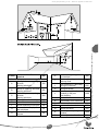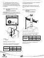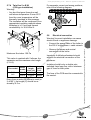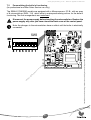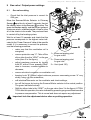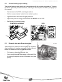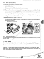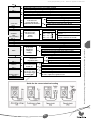
1
www.gotoplumbing.co.uk - Boiler & Appliance Manuals HIGH EFFICIENCY CONDENSING COMBINATION BOILER Instructions for use Installation and servicing G.C. 47-920-51 Semia Condens F30 E G.C. 47-920-52 w w w .g ot op l um bi ng .c o. uk -B oi le r& Ap pl ia nc e M an u al s Semia Condens F24 E w w w .g ot op l um bi ng .c o. uk -B oi le r& Ap pl ia nc e M an u al s www.gotoplumbing.co.uk - Boiler & Appliance Manuals www.gotoplumbing.co.uk - Boiler & Appliance Manuals Instructions for use Important information ...........................................................2 2 Guarantee registration..........................................................3 3 Appliance use ........................................................................4 4 Servicing ................................................................................4 5 Recycling ...............................................................................4 6 Operating the boiler (user instructions) .............................5 ia nc e M an u Control panel ................................................................................5 Commissioning and lighting .........................................................5 To program daily timeclock ...........................................................5 Temperature adjustment ...............................................................6 Ap pl 6.1 6.2 6.3 6.4 al s 1 Turn the boiler off ..................................................................6 8 Fault finding...........................................................................6 9 Frost protection.....................................................................9 .c ng bi um w .g ot op l Maintenance/After Sales Service .........................................9 w 10 Boiler frost protection ...................................................................9 Frost protection activation ............................................................9 w 9.1 9.2 o. uk -B oi le r& 7 1 Instructions for Use Index www.gotoplumbing.co.uk - Boiler & Appliance Manuals 1 Important information WARNINGS Gas Leak or Fault Turn off the gas emergency control valve immediately. Eliminate all sources of ignition, i.e. smoking, blowlamps, hot air guns, etc. Do not operate electrical lights or switches either on or off. Open all doors and windows, ventilate the area. Sheet Metal Parts This boiler contains metal parts (components) and care should be taken when handling and cleaning, with particular regard to edges. Sealed Components Under no circumstances must the User interfere with or adjust sealed parts. Control of Substances Hazardous to Health This boiler is for use only on G20 natural gas, but the 30cxi may be converted for use on G31 gas (Propane L.P.G.). Under Section 6 of The Health and Safety at Work Act 1974, we are required to provide information on substances hazardous to health. The adhesives and sealants used in this appliance are cured and give no known hazard in this state. al s Gas Category an u Gas Safety (Installation and Use) Regulations In your own interests and that of safety, it is the Law that ALL gas appliances are installed by a competent person in accordance with the current issue of the above regulations. M Insulation Pads / Ceramic Fibre nc e These can cause irritation to skin, eyes and the respiratory tract. If you have a history of skin complaint you may be susceptible to irritation. High dust levels are usual only if the material is broken. Normal handling should not cause discomfort, but follow normal good hygiene and wash your hands before eating, drinking or going to the lavatory. If you do suffer irritation to the eyes or severe irritation to the skin seek medical attention. Ap r& le oi -B uk This boiler is tested and certificated for safety and performance. It is, therefore, important that no alteration is made to the boiler, without permission, in writing, by Saunier Duval. Any alteration not approved by Saunier Duval, could invalidate the certification, boiler warranty and may also infringe the current issue of the statutory requirements. pl ia Testing and Certification o. CE Mark w w w .g ot op l um bi ng .c This boiler meets the requirements of Statutory Instrument, No. 3083 The Boiler (Efficiency) Regulations, and therefore is deemed to meet the requirements of Directive 92/42/EEC on the efficiency requirements for new hot water boilers fired with liquid or gaseous fuels. Type test for purposes of Regulation 5 certified by: Notified body 0087. Product/production certified by: Notified body 0086. The CE mark on this appliance shows compliance with: 1. Directive 90/396/EEC on the approximation of the laws of the Member States relating to appliances burning gaseous fuels. 2. Directive 73/23/EEC on the harmonisation of the Laws of the Member States relating to electrical equipment designed for use within certain voltage limits. 3. Directive 89/336/EEC on the approximation of the Laws of the Member States relating to electromagnetic compatibility. 2 Electrical Supply The boiler must be earthed. All system components shall be of an approved type and all wiring to current I.E.E. wiring regulations. External wiring must be correctly earthed, polarised and in accordance with the relevant standards. In GB this is BS 6891. In IE this is the current edition of I.S.813 “Domestic Gas Installations”. The boiler must be connected to a permanent 230V ac, 50Hz supply. Connection of the whole electrical system of the boiler, including any heating controls, to the electrical supply must be through one common isolator and must be fused 3 Amp maximum. Isolation should be by a double pole switched fused spur box, with a minimum gap of 3mm for both poles. The fused spur box should be readily accessible and preferably adjacent to the appliance. It should be identified as to its use. Alternatively connection can be made through an unswitched shuttered socket and 3A fused 3-pin plug both to the current issue of BS 1363 may be used, provided they are not used in a room containing a bath or shower. Wiring to the boiler must be PVC 85°C insulated cable, not less than 0.75mm2 (24/0.20mm). www.gotoplumbing.co.uk - Boiler & Appliance Manuals Thank you for installing a new Saunier Duval appliance in your home. Saunier Duval appliances’ are manufactured to the very highest standard so we are pleased to offer our customers’ a Comprehensive Guarantee. This product is guaranteed for 24 months from the date of installation or 30 months from the date of manufacture, whichever is the shorter, for parts. In addition this product is guaranteed for 12 months from the date of installation or 18 months from the date of manufacture, whichever is the shorter, for labour. The second year of the parts guarantee, from the beginning of the 13th month onwards after installation, is conditional upon the boiler having been serviced by a CORGI registered gas installer, in accordance with the manufacturer’s recommendations. We strongly recommend regular servicing of your gas appliance, but where the condition is not met, any chargeable spare parts of components issued within the applicable guarantee period still benefit from a 12 month warranty from the date of issue by the manufacturer. We recommend you complete and return as soon as possible your guarantee registration return literature, supplied in the document envelope. If your guarantee certification return literature is missing you can obtain a copy by telephoning the Saunier Duval Customer Service number 00 44 (0)1773 525914. al s REGISTER YOUR SAUNIER DUVAL APPLIANCE DIRECTLY BY CALLING nc e M an u 00 44 (0)870 240 3413 ng .c o. uk -B oi le r& Ap pl ia Customer service: Saunier Duval GB Great Britain: Tel. 00 44 (0)1773 525914 Fax. 00 44 (0)1773 828070 Saunier Duval, Nottingham Road, Belper, Derbyshire. DE56 1JT w w w .g ot op l um bi Saunier Duval IE Ireland: Tel. 00 3531 4508120 Taney Distribution Unit 4, Riverside Industrial Estate Bluebell Avenue Dublin 12 Technical Advice Line: Tel. 00 44 (0)1773 828400 General and Sales enquires: Tel. 00 44 (0)870 606 4351 Fax. 00 44 (0)1773 820569 The code of practice for the installation, commissioning & servicing of gas central heating 3 Instructions for Use 2 Guarantee registration www.gotoplumbing.co.uk - Boiler & Appliance Manuals 3 Appliance use 4 Servicing Saunier Duval’s appliances are manufactured according to the latest technical evolutions and current safety regulations. • Clean the case of the appliance with wet soapy cloth. • Do not use any abrasive cleaning product as they could damage the housing or plastic parts. This appliance is used to produce hot water using gas. Any other use is considered inappropriate and is forbidden. • Also see section 12 & 35. 5 Recycling The manufacturer shall not be responsible for any damage caused by another use. In that case the user shall be the responsible party. w w w .g ot op l um bi ng .c o. uk -B oi le r& Ap pl ia nc e M an u al s The appliance comprises many recyclable parts. The packaging, the appliance and the content of the package shall not be thrown together with domestic waste but eliminated according to the current regulations. 4 www.gotoplumbing.co.uk - Boiler & Appliance Manuals 6 Operating the boiler (user instructions) Control panel 5 1 7 6 9 2 8 3 4 10 s 6.3 al 6.2 Pressure gauge Safety lockout indicator Timeclock Timeclock toggles Timeclock mode selector an u 6 7 8 9 10 pl To program daily timeclock Ap Commissioning and lighting ia nc e M Legend 1 Operating indicator 2 Operating mode selection 3 Heating temperature adjustment 4 DHW temperature adjustment 5 Display of the temperature / error codes Set the current time, by turning the dial [8] clockwise until the current time is shown against the indicator ‘ ’. oi -B uk - the boiler is connected to the electrical supply (the green indicator [1] blinks). le r& • Make sure that: .c o. - the gas service cock is open. bi ng • Turn the selector [2] bringing it in the or WINTER position. SUMMER The operating indicator [1] on the control panel turns on: the boiler is ready to run. Push in plastic toggles [9] against the time you wish the heating to be off. w w .g ot op l um The timeclock can operate in three positions: automatic ‘ ’, heating permanently off ‘0’, and heating permanently on ‘1’. w • Turn the selector [2] to modify the operating mode of the boiler: To select, move the lever [10] to the desired position. Central heating and domestic hot water NOTE: In case the electrical supply fails the timeclock will not operate as it has no back-up battery backup. Therefore, it will be necessary to reset the current time once electrical supply is restored. Domestic hot water only Installer mode 0 reset Stand-by and appliance frost protection 5 Instructions for Use 6.1 www.gotoplumbing.co.uk - Boiler & Appliance Manuals 6.4 Temperature adjustment 7 Turn the boiler off • Turn the selector [2] on the 0 / reset position (the green indicator [1] blinks). 6.4.1 Domestic hot water temperature adjustment [4] to adjust the • Turn the knob domestic hot water max temperature. We advise you to turn off the appliance gas supply if you leave home for a long period. 6.4.2 Heating temperature adjustment • Turn the knob [3] to change the heating system temperature. 8 Fault finding s [1] an u al GREEN LED M The green led can be off, flashing (slowly or rapidly) or on. le r& Ap pl ia nc e OFF: the boiler is electrically disconnected. In these conditions the boiler obviously doesn’t work. The Automatic Anti Freezing and Anti Blocking functions can’t be activated (prevents damage to boiler during long period of inactivity). The external general switch could be off. ng .c o. uk -B oi FLASHING (slowly): the boiler has power but the SUMMER/WINTER Selector is in central position (0). The boiler will not provide heating or hot water but the boiler protection systems are operating (Anti Freezing and Anti Blocking functions may ignite the boiler and as such require the gas supply to be open). op l um bi FLASHING (rapidly): the Chimneysweep Function (which is reserved for the installer) is on by mistake. w w w .g ot Turn it off bringing the SUMMER/WINTER selector on the central position (0) until the green led flashes slowly. ON: the boiler is on and the SUMMER/WINTER selector is in the SUMMER Position or in the WINTER Position. The boiler will provide heating and hot water on demand. 5 1 7 6 9 2 8 3 4 10 6 www.gotoplumbing.co.uk - Boiler & Appliance Manuals RED LED [7] - FAULT CODES AND LOCKOUTS Led OFF: the boiler is functioninging correctly. Led FLASHING: signals a boiler fault. The display [5] will show a fault code: Fault code “06” - the heating system temperature sensor (inside the boiler) is damaged. Call a Qualified Technician to repair. Led ON - The display [5] shows a flashing code. Things to try: Code “01” - If the boiler has just been installed, or adjustments have been made to the gas pipes. al s If the air-gas mix ratio is incorrect then this will prevent combustion and can force the boiler into a state of lockout. In order to correct the mix you should repeat the ignition process several times with the SUMMER/WINTER Selector on the 0 / reset position until the red led turns off. an u Code “01” - Ignition problems if no work has been carried out. Ap pl ia nc e M Ensure that the SUMMER/WINTER selector is on the 0 / reset position until the red led turns off. If this does not happen or the boiler goes back into lockout please ask your installer to check the following points: Check the CO2 levels of the boiler are correct. Please refer to Technical Data table in the section reserved for installers (in this manual); • Check the flue outlet for leaks and inspect general condition clearliness. Please refer to “Flue connection” in the section reserved for installers (in this manual). .c o. uk -B oi le r& • um bi ng Technical Note for the TECHNICIAN: if the Flame Control Unit is not detecting a flame it could be due to one of the following reasons: op l • the flame has not ignited; w w w .g ot • the flame control unit has become disconnected from the burner. 7 Instructions for Use The red led [7] can be off, flashing or on. www.gotoplumbing.co.uk - Boiler & Appliance Manuals Code “05” - The boiler is overheating and the Safety Thermostat has triggered. Move the SUMMER/WINTER Selector on the 0 / reset position until the red led turns off (this may take a while to allow the boiler to cool). Once the led is off move the selector to the desired position (Summer or Winter ). If the boiler locks out again please call the group service for assistance. Code “05” - The boiler flue is overheating and the Flue Safety Thermostat has triggered; The thermostat must be replaced by the installer. Please try the following process, if it does not work then call group service for assistance. Move the SUMMER/WINTER Selector on the 0 / reset position until the red led turns off (this may take a while to allow the boiler to cool). Once the led is off move the selector to the desired position (Summer or Winter ). If the boiler locks out again please call the group service for assistance. Code “21” - You have insufficient water pressure (0.5 bar or lower). M an u al s Repressurise the system to the optimum pressure of between 1-1,5 bar (cold) by following the procedure outlined in the paragraph “Commissioning” in the section reserved for installers (in this manual). w w w .g ot op l um bi ng .c o. uk -B oi le r& Ap pl ia nc e If a system continues to lose pressure it would suggest a system leak and the system should be inspected for water loss. Also check that all radiators bleed points are closed or have not been recently opened before checking the system. 8 9 Frost protection 10 Maintenance/After Sales Service 9.1 Please note that an incorrectly serviced appliance can affect the safety of the appliance and can lead to injury. Boiler frost protection In case of frost risk, do as follows: • Make sure the boiler is supplied with electrical power and gas. To ensure the continued efficient and safe operation of the appliance it is recommended that it is checked and serviced as necessary at regular intervals. The frequency of servicing will depend upon the particular installation conditions and usage, refer to guarantee registration. • Turn the selector [2] on the 0 / reset position (the green indicator [1] blinks). The frost protection system operates the boiler as soon as the temperature in the heating circuit is under 5°C. The boiler stops as soon as the water temperature in the heating circuit reaches 30°C. an u Frost protection activation M 9.2 al s If this appliance is installed in a rented property there is a duty of care imposed on the owner of the property by the current issue of the Gas Safety (Installation and Use) Regulations, Section 35. Servicing/ maintenance should be carried out by a competent person in accordance with the rules in force in the countries of destination. To obtain service, please call your installer or Saunier Duval service team. -B w w w .g ot op l um bi ng .c o. uk • If you leave home for a long period, see chapter “Draining of the appliance” in the section reserved for installers (in this manual). oi le r& Ap pl ia nc e • If you leave home for a few days, select the minimum heating temperature on the control panel of the boiler and just decrease the setpoint temperature on your room thermostat. 9 Instructions for Use www.gotoplumbing.co.uk - Boiler & Appliance Manuals www.gotoplumbing.co.uk - Boiler & Appliance Manuals Installation and servicing Index 1 Comments on the instructions ..........................................12 2 Appliance description.........................................................12 2.1 2.2 2.3 Data label ...................................................................................12 Mandatory WARNING for EEC countries ...................................12 Block diagram .............................................................................13 3 Appliance location ..............................................................13 4 Safety instructions and regulations ..................................14 al an u Appliance installation .........................................................16 w w .g ot op l um bi ng .c o. uk -B oi le r& Ap pl ia Recommendations before mounting ..........................................16 Dimensions .................................................................................17 List of delivered equipment ........................................................18 Fixing to the wall .........................................................................18 Gas and water connection ..........................................................19 Connection to the condensate trap ............................................20 Flue connection ..........................................................................22 Flue restrictor .............................................................................22 Horizontal concentric flue Ø 60/100 (C13 type installation) ...... 24 Vertical concentric flue Ø 60/100 (C33 type installation) ........... 24 Twin flue 2 x Ø 80 (C53 type installation) ...................................25 Electrical connection ..................................................................25 External controls .........................................................................26 Wiring diagram ...........................................................................28 w 5.1 5.2 5.3 5.4 5.5 5.6 5.7 5.7.1 5.7.2 5.7.3 5.7.4 5.8 5.8.1 5.9 nc e M 5 Safety instructions ......................................................................14 Regulations ................................................................................15 s 4.1 4.2 6 Commissioning ...................................................................29 7 Specific adjustments ..........................................................29 7.1 7.2 8 Pump speed ...............................................................................29 Personalizing the boiler’s functioning .........................................31 Draining of the appliance ...................................................32 8.1 Heating circuit .............................................................................32 10 www.gotoplumbing.co.uk - Boiler & Appliance Manuals 9 Gas valve / Output power settings ....................................33 9.1 9.2 9.3 9.4 9.5 Gas valve setting ........................................................................33 Central heating output setting ....................................................34 Domestic hot water flow rate setting ..........................................34 Slow opening setting ..................................................................35 Changing gas type .....................................................................35 Fault finding.........................................................................35 11 Control / Commissioning ...................................................38 12 User information .................................................................38 13 Spare parts ..........................................................................38 14 Maintenance ........................................................................39 16 um .g ot w Technical data .....................................................................43 16.1 17 To replace fan .............................................................................40 To replace air pressure switch ....................................................40 To replace pump .........................................................................41 To replace gas valve ...................................................................41 To replace domestic heat exchanger..........................................42 To replace thermistor ..................................................................42 To replace overheat thermostat ..................................................42 w 15.1 15.2 15.3 15.4 15.5 15.6 15.7 op l Replacement of parts..........................................................40 w 15 Burner pressure tables ...............................................................44 Boiler schematic .................................................................45 11 Installation and servicing instructions strictly reserved for qualified gas installers ng .c o. uk -B oi le r& Casing ........................................................................................39 Combustion chamber .................................................................39 Burner .........................................................................................39 Heat exchanger ..........................................................................39 Reassembly of parts removed for servicing ...............................40 Flue system ................................................................................40 Operation of fan ..........................................................................40 bi 14.1 14.2 14.3 14.4 14.5 14.6 14.7 Ap pl ia nc e M an u al s 10 www.gotoplumbing.co.uk - Boiler & Appliance Manuals Member States relating to appliances burning gaseous fuels. 1 Comments on the instructions • Please give all of the instructions to the user. The user shall keep them for future reference. We accept no liability in case of damage due to the non-compliance of the instruction manual. - Directive 73/23/EEC on the harmonisation of the Laws of the Member States relating to electrical equipment designed for use within certain voltage limits. - Directive 89/336/EEC on the approximation of the Laws of the Member States relating to electromagnetic compatibility. IMPORTANT. With regards to the Manual Handling Operations, 1992 Regulations, the following lift operations are recommended as the appliance weight exceeds a one-man lift. 2 Appliance description 2.1 Data label The data label certifies the origin where the product was manufactured and the country for which it is intended. Warning! The appliance shall only be used with the gas types indicated on the data label. M an u al s • Clear the route before attempting the lift. e ia nc Mandatory WARNING for EEC countries Ap pl • Keep load as close to body as possible. le r& • Do not twist - reposition feet instead. oi • If two persons performing lift, ensure co-ordinated movements during lift. .c o. uk This appliance is designed, approved and inspected to meet the requirements of the intended market. The data label indicates where the product was manufactured and the country for which it is intended. -B 2.2 • Ensure safe lifting techniques are used - keep back straight - bend using legs. w w w .g ot op l um bi ng This appliance meets the requirements of Statutory Instrument, No. 3083 The Appliance (Efficiency) Regulations, and therefore is deemed to meet the requirements of Directive 92/42/EEC on the efficiency requirements for new hot water appliances fired with liquid or gaseous fuels. • Always use assistance if required. Manufacturer’s instructions must not be taken as overriding statutory requirements. Reference in these instructions to British standards and statutory regulations/ requirements apply only to the United Kingdom. For Ireland the current edition of I.S.813 «Domestic Gas Installations» must be used. This appliance certificated to the current issue of EN 483: 2000 for performance and safety. It is important that no alteration is made to the appliance, without permission, in writing, from Saunier Duval. Any alteration that is not approved by Saunier Duval could invalidate the warranty and could also infringe the current issue of the Statutory Requirements. Type test for purposes of Regulation 5 certified by: Notified body 0063. Product/ production certified by: Notified body 0086. The CE mark on this appliance shows compliance with: - Directive 90/396/EEC on the approximation of the laws of the 12 www.gotoplumbing.co.uk - Boiler & Appliance Manuals 2.3 Block diagram FLUE 1 2 4 5 6 7 8 9 10 11 12 13 14 15 16 17 18 19 20 21 Drain valve Pressure gauge / thermometer By-pass Pump Heating system safety valve 3 bar Expansion vessel Overheat thermostat Condense syphonic trap Automatic air vent Recuperator Flue overheat safety thermostat Air pressure switch Fan Flue hood Primary heat exchanger Burner Thermistor Hydraulic 3-way valve Water valve Domestic plate to plate heat exchanger 22 Gas valve 23 low pressure sensor DOMESTIC WATER .g ot w • In IE reference should be made to the current edition of I.S.813 «Domestic Gas Installations» and the current ETCI rules. w w 3 Appliance location • This appliance is not suitable for outdoor installation. • Make sure you keep the minimum clearances to ensure total accessibility for servicing. Top: 150 mm; bottom: 200 mm; side: 5 mm. • This appliance may be installed in any room, although particular attention is drawn to the installation of an appliance in a room containing a bath or shower where reference must be made to the relevant requirements. In GB this is the current I.E.E. WIRING REGULATIONS and BUILDING REGULATIONS. • The appliance must be mounted on a flat wall, which is sufficiently robust to take its weight. 13 Installation and servicing instructions strictly reserved for qualified gas installers INLET (white) FLOW (green) GAS (white) op l um HEATING OUTLET (black) bi ng .c o. WARNING: This schematic is for information only. RETURN (green) uk -B oi le r& Ap pl ia nc e M an u al s CONDENSE (orange) www.gotoplumbing.co.uk - Boiler & Appliance Manuals • The appliance is room sealed, so when it is installed in a room or space, a permanent air vent is not required. to provide information on substances hazardous to health. The adhesives and sealants used in this appliance are cured and give no known hazard in this state. • Do not install the appliance above another appliance that could damage it (for example, above a cooker that might emit steam or grease) or in a room, which has a lot of dust in the atmosphere which is corrosive. In the event of the appliance overheating the safety devices will cause a safety shutdown. If this happens, call your installation/servicing company. 4 Safety instructions and regulations Warning! This appliance must be earthed. This appliance must be wired in accordance with these instructions. Any fault arising from incorrect wiring cannot be put right under the terms of the Saunier Duval guarantee. al pl ia nc e M an u The following safety instructions must be imperatively followed during the maintenance and the replacement of spare parts. r& Ap • Stop the appliance (see chapter “Turn the boiler off” in the “Instructions for use” section, in this manual). oi le Safety instructions • Deactivate the appliance from the mains power supply with the socket or the double-pole switch (with a minimum gap of 3mm for both poles). um bi ng .c o. uk If the gas pressure at the input of the appliance is outside the range specified, you shall not start the appliance. If the cause of the problem cannot be found nor solved, please contact the Gas Utility company. -B 4.1 s This appliance is tested and certificated for safety and performance. It is, therefore, important that no alteration is made to the appliance, without permission, in writing, from Saunier Duval. Any alteration not approved by Saunier Duval, could invalidate the certification, appliance warranty and may also infringe the current issue of the statutory requirements. op l • Turn off the gas control valve. .g ot • Close the shut off valves located on the connection sockets. w w Warning! Incorrect installation can cause electric shock or appliance damage. w • Drain the appliance when you want to change the hydraulic parts of the appliance. - When making the connections, locate the sealing washers properly so as to avoid any gas or water leakage. • Let the appliance cool down before undertaking any maintenance operation. - Never use a wire brush or stiff-bristle scrubbing brush to clean the heat exchanger as this could damage the appliance. • Protect all the electrical components from water when you achieve any operations. - Under no circumstances must the User interfere with or adjust sealed parts. Under Section 6 of The Health and Safety at Work Act 1974, we are required • Use only new O-rings and gaskets. 14 www.gotoplumbing.co.uk - Boiler & Appliance Manuals • After having carried out work on the gas carrying components check that they are correctly fitted and sealed by checking for leaks. reference should be made to the current ETCI rules for Electrical Installation. In GB the following Codes of Practice apply: BS4814, BS6798, BS5440 Part 1 and 2, BS5546 Part 1, BS5449, BS6891, BS6700, BS7074 Part 1 and 2, BS7593, BS7671. In IE: I.S.813, BS5546, BS 5449, BS 7074, BS 7593. • When the work is complete check the boiler operates correctly. 4.2 Regulations When installing and commissioning the appliance, the regulations below shall be observed in their current version: Where no British Standard exists, materials and equipment should be fit for their purpose and of suitable quality and workmanship. The installation of this appliance must be carried out by a competent person in accordance the rules in force in the countries of destination. Manufacturer’s instructions must not be taken as overriding statutory requirements. an u al s In your own interests and that of safety, it is the Law that ALL gas appliances must be installed by a competent person only, in accordance with the current issue of the above regulations. Ap pl If the appliance is to be installed in a timber frame building it should be fitted in accordance with the Institute of Gas Engineers document IGE/UP/7/1998. If in doubt seek advice from the local gas undertaking or Saunier Duval. -B uk - The Gas Safety (Installation and Use) Regulations. oi le r& - The manufacturer’s instructions supplied. .c o. - The appropriate Buildings Regulations either The Building Regulations, The Building Regulations (Scotland), The Building Regulations (Northern Ireland). op l um bi ng The installation is subject to building regulation approval, notify the Local Authority of intention to install. w .g ot - The Water Fittings Regulations or Water byelaws in Scotland. w w - The Health and Safety at Work Act, Control of Substances Hazardous to Health (COSHH). - The Current I.E.E. Wiring Regulations. Where no specific instructions are given, reference should be made to the relevant British Standard Code of Practice. In IE, the installation must be carried out by a competent person and installed in accordance with the current edition of I.S.813 «Domestic Gas Installations», the current Building Regulations and 15 Installation and servicing instructions strictly reserved for qualified gas installers ia nc e M In GB the installation of the appliance must be carried out by a competent person as described in the following regulations: www.gotoplumbing.co.uk - Boiler & Appliance Manuals that is really required without taking into account the maximum power that the boiler can supply. Nevertheless, we advise you to have a flow big enough so that the temperature difference between outgoing and return is under or equal to 20°C. The minimum flow rate is indicated in the chapter “Technical Data” at the end of this instruction manual. 5 Appliance installation All the dimensions in this chapter are expressed in mm. 5.1 Recommendations before mounting 5.1.1 Domestic hot water circuit design The circuit should be designed to avoid any unnecessary flow losses (decrease the number of elbows). The piping route should be designed in such a way that it avoids any air locks and make purging of gas from the system easier. Bleeders should be placed at each high point of the system as well as on any radiators. Total water volume accepted by the heating circuit depends, amongst other things, on the cold static load. The expansion tank fitted in the boiler is delivered set in plant (see chapter “Technical Data” at the end of this instruction manual). At commissioning, it is possible to change this pressure in case of a larger static load. We advise you to provide a drain valve at the lowest point of the system. an u al s The boiler will operate with a minimum supply pressure but with a low flow. Optimum performance will be achieved with a pressure of 1 bar (cold). M 5.1.2 Heating circuit design uk .c o. Warning: If the materials used are of a different type, some corrosion can occur. In that case, we advise you to add an inhibitor to the heating circuit water (according to the manufacturer’s recommendations) that could avoid gas production and oxide formation. -B oi le r& Ap pl ia nc e SEMIA CONDENS boilers can be used for any kind of installation: serial or derivated double tube, single tube, under floor heating, etc... Heating surfaces can be made up with heaters, convectors or unit heaters. .g ot op l um bi ng If thermostatic radiator valves are used, we advise you not to fit in a room where a room thermostat is fitted. w w • In case of an old installation, the system should be flushed. See section 5.1.4. w The pipework sections should be fixed by using the following flow/pressure curve (see chapter “Heating circuit adjustment”). The system will be calculated according to the flow corresponding to the power • If the boiler is not immediately set, protect all the pipe fittings so as to avoid that any plaster element or paint could impede the connection. 16 www.gotoplumbing.co.uk - Boiler & Appliance Manuals 5.1.3 Water treatment In the case of an existing installation, it is Essential that prior to installing the new boiler the system is thoroughly flushed. For optimum performance after installation of a new system, the boiler and its associated central heating system should also be flushed. Flushing should be carried out in accordance with BS7593: 1992 using a cleanser such as Sentinel X300 or X400, Fernox Superfloc or Salamander corrosion guard cleaner. For long-term corrosion protection, after flushing, an inhibitor suitable for stainless steel heat exchangers should be used, refer to the current issue of BS 5449 and BS 7593 on the use of inhibitors in central heating systems. Examples are Sentinel X100 Fernox or Salamander corrosion guard inhibitor. Dimensions 284 223 s Cold water inlet (white) Room thermostat Electrical power supply Gas (white) 116 223 -B uk 750 2 w 942_1 .g ot 39 40 30 46 53 w 88 w 52 52 op l SC 1 941_2 um C F TL G 13 R M bi ng .c o. 735 oi le r& Ap pl ia CONNECTIONS FOR FLUE 17 1 Flue products outlet 2 Air inlet for concentric system Installation and servicing instructions strictly reserved for qualified gas installers nc e M 116 347 F T L G al 400 R Heating return (green) M Heating flow (green) SC Condense outlet (orange) (flexible pipe) C Hot water outlet (black) an u 5.2 www.gotoplumbing.co.uk - Boiler & Appliance Manuals 5.3 List of delivered equipment The boiler is delivered in two packages: - The boiler - One isolating valve pack: - 2 heating isolating valves - 1 domestic cold water isolating valves - 1 gas isolating valves - One safety discharge pipe pack: - 1 safety discharge pipe - 1 1/2 in. gasket e M an u al s - One installation and documentation pack: - 1 user and installation manual - 1 guarantee envelope - 1 gas conversion instructions sheet - 1 log book - 1 condense drain pipe - a set of 1/2 in. gaskets - a set of 3/4 in. gaskets ng .c o. uk -B oi le r& Ap pl ia nc - One pipe pack: - 2 central heating pipes - 2 gas/cold water pipes - 1 hot water pipe - a set of 1/2 in. gaskets - a set of 3/4 in. gaskets - 1 wall template - 1 hanging bracket w w Fixing to the wall w 5.4 .g ot op l um bi The flue is supplied separatly and will depend upon the configuration of the installation. • Make sure the material you use fits those of the appliance. 18 WHITE WHITE BLACK ORANGE GREEN GREEN 1033_R01 • Chose the location of the appliance. See chapter “Appliance location”. www.gotoplumbing.co.uk - Boiler & Appliance Manuals • The hanging bracket will be adapted to the features of the bearing wall and will have to take into account the weight of the boiler (please refer to Technical Data table in this manual);. The heating safety discharge valve must be connected, using not less than 15mm o.d. pipe, to discharge, in a visible position, outside the building, facing downwards, preferably over a drain. • Drill the holes for the fixing screws in accordance to the diagram below and to the size of the wall template delivered with the appliance. The pipe from the safety discharge valve must not discharge above an entrance, window or any type of public access area. • Set the seals on the different pipe fittings. The pipe must have a continuous fall and be routed to a position so that any discharge of water, possibly boiling, or steam cannot create any danger to persons, damage to property or external electrical components and wiring. • Make connections to boiler, gas, water and heating cocks with the tube assemblies supplied in piping pack. To ease future servicing it is advisable to use a compression type fitting to extend the safety discharge valve tube. 5.5 Warning! Relief valve connections should not be used for any other purpose. • Place the boiler above the hanging bracket. Ap r& le oi -B um bi ng .c o. uk • Before undertaking any operation, carefully clean the pipes with an appropriate product in order to remove impurities such as filings, welds, different oils and greases that may be present. These foreign bodies may enter the boiler and disrupt the operation. pl ia nc Gas and water connection .g ot op l • Do not use any solvents that could damage the heating circuit. w w w • Do not brase the nozzles set on place: this operation could damage the seals and the taps tightness. • Only use the genuine seals delivered with the appliance. • Check that there is no leakage. Repair if need be. 19 Installation and servicing instructions strictly reserved for qualified gas installers e M an u al s • Slowly lower the boiler. www.gotoplumbing.co.uk - Boiler & Appliance Manuals 5.6 Connection to the condensate trap • Connect the flexible pipe to a discharge system leading to the sewer in compliance with the instructions below: OK • Use the condensate drain flexible connection pipe supplied. • Ensure there is a conbinual fall of 2.5° (44 mm/m). • Do not let the condensate drain flexible connection fall into the trap. • Do not use copper pipes. OK w w w .g ot op l um bi ng .c o. uk -B oi le r& Ap pl ia nc e M an u al s Important notice: The float in the condensate trap also ensures fume tightness. Therefore, it is not necessary to add water in the condensate trap. 20 21 um op l .g ot w uk o. .c ng bi -B r& le oi Ap ia pl e nc Installation and servicing instructions strictly reserved for qualified gas installers w w 1041_R00 al an u M s www.gotoplumbing.co.uk - Boiler & Appliance Manuals www.gotoplumbing.co.uk - Boiler & Appliance Manuals Different flue outlet configurations can be carried out. • Whatever the kind of flue system chosen, observe the minimum distances indicated in the chart on the next page to position the flue terminals. • Consult your supplier for more information about the other possibilities and associated accessories. 5.7.1 Flue restrictor 5.7 Flue connection Depending on the length of the flue system, it may be necessary to install the flue restrictor “D”. The length of the system is specified for each flue configuration. Warning! You can only use flue accessories approved for the SEMIA CONDENS. Then, install the plastic adaptor “A”. al s A D w w w .g ot op l um bi ng .c o. uk -B oi le r& Ap pl ia nc e M an u Saunier Duval’s horizontal flue automatically provides a 3° angle that enables the return of the condensates to the appliance. 22 www.gotoplumbing.co.uk - Boiler & Appliance Manuals S Position of the flue terminal Horizontal flues directly below an opening, A air brick, opening windows above an opening, air brick, B opening windows horizontally to an opening, C air brick, opening windows D below gutter, drain/soil pipe E below eaves F below a balcony or car port from vertical drain pipes G and soil pipes from internal/external H corners to a boundary alongside the terminal above adjacent ground or I balcony level from surface or a boundary J facing the terminal K facing terminals from opening (door/ L window) in car port into dwelling M vertical from a terminal N horizontally from a terminal Vertical flues P from another terminal Q above roof level from adjacent opening R window S from adjacent wall to flue mm H* 300 w w w .g ot op l um bi Position 300 300 25 25 25 25 25 23 300 300 600 1200 1200 1500 300 600 300 1000 300 Installation and servicing instructions strictly reserved for qualified gas installers ng .c o. uk -B oi le r& Ap pl ia nc e M an u al s R www.gotoplumbing.co.uk - Boiler & Appliance Manuals H*: This dimension comply with the building regulations, but it may need to be increased to avoid wall staining and nusance from pluming depending on site conditions. A Plume mangement kit can be installed at the extremity of the duct. Every time a 90° elbow is used (or 2 off 45°), the length (L) should be reduced by 1 m. 5.7.2 Horizontal concentric flue Ø 60/100 (C13 type installation) 5.7.3 Vertical concentric flue Ø 60/100 (C33 type installation) e M L r& Ap pl ia nc 45° an u 1035_R01 al s IMPORTANT: turn the coaxial socket 45° (as shown in the picture) when horizontal concentric flue Ø 60/100 is used. -B oi le L o. uk 1 ng 1034_R00 Flue model w .g ot op l um bi This value is reached with the length of the maximum duct (L) + 1 90° elbow. w Ø 60/100 vertical w Legend 1 Gasket This value is reached with the length of the maximum duct (L) + 1 90° elbow. Ø 60/100 horizontal Boiler model F24 E F30 E Boiler model F24 E F30 E Restrictor Max. length L if length 5m <2m 4m <1m Every time an extra 90° elbow is used (or 2 off 45°), the length (L) should be reduced at by 1 m. Maximum flue index: 150 Pa Flue model Maximum flue index: 150 Pa .c 72 Restrictor Max. length L if length 4m <2m 3m <1m 24 www.gotoplumbing.co.uk - Boiler & Appliance Manuals For separator correct and wrong positions, refer to the following diagram: 5.7.4 Twin flue 2 x Ø 80 (C53 type installation) Warning! LL21 1043_R00 - Any duct that goes through a wall and whose temperature is over 60°C from the room temperature will be thermally insulated at this passage. The insulation will be composed of an appropriate insulating material whose thickness is ≥ 10 mm and thermal conductibility λ ≤ 0.04 W/m.K. L1 5.8 Electrical connection Warning! Incorrect installation can cause electric shock or appliance damage. al s 188 pl ia nc • Observe the phase and neutral connection on the boiler. Ap Maximum flue index: 150 Pa r& le oi -B uk o. This value is reached with 2 elbows, the separator and the maximum duct length (L1+L2). Important: A skilled professional should achieve the electrical connection of the appliance. .c F24 E F30 E ng Ø 80 twin Max. Restrictor length if length L1+L2 L1+L2 (L2) 10 (9) m always 10 (9) m always bi Boiler model um Flue model Isolation should be by a double pole switched fused spur box, with a minimum gap of 3mm for both poles. w w .g ot op l The fuse of the PCB must be connected to the neutral. w Every time an extra 90° elbow is used (or 2 off 45°), the length (L) should be reduced by 0.5 m. 25 Installation and servicing instructions strictly reserved for qualified gas installers e M an u • Connect the power cable of the boiler to the 230 V single-phase + earth network. www.gotoplumbing.co.uk - Boiler & Appliance Manuals 5.8.1 External controls The boiler will work for heating AS DELIVERED without a room thermostat fitted provided the two wires on the integral external controls lead REMAIN LINKED TOGETHER. ANY EXTERNAL HEATING CONTROL MUST BE POTENTIAL FREE (see Figure 1). ON NO ACCOUNT MUST ANY ELECTRICAL VOLTAGE BE APPLIED TO EITHER OF THE TERMINALS OF THE WHITE EXTERNAL CONTROLS LEAD WARNING: This boiler must be wired in accordance with these instructions. Any fault arising from incorrect wiring may invalidate the terms of the guarantee. 1) INTERNAL TIME CLOCK WITH EXTERNAL ROOM THERMOSTAT If a room thermostat is required it must be connected to the external controls lead as shown in figure 1, using a suitable electrical connection. POTENTIAL FREE ROOM THERMOSTAT an u al s FUSED MAINS SPUR OR FUSED 3 PIN PLUG 617R01 le WHITE EXTERNAL CONTROL LEAD oi BLACK MAINS LEAD r& Ap pl ia nc e M BOILER -B Internal time clock (factory fitted) External potential-free room thermostat CONNECTION WITH EXTERNAL PROGRAMMER um bi 2) ng .c o. uk Figure 1 .g ot op l Any eventual external programmer must be connected in series with the room thermostat (see figure 2) w w w IMPORTANT: the boiler time clock must be linked across (see the REMARK below) FUSED MAINS SPUR OR FUSED 3 PIN PLUG PROGRAMMER ROOM THERMOSTAT BOILER Figure 2 WHITE EXTERNAL CONTROL LEAD Internal time clock (factory fitted) disconnected External potential-free room thermostat External potential-free programmer 26 617A BLACK MAINS LEAD www.gotoplumbing.co.uk - Boiler & Appliance Manuals 3) CONNECTION WITH EXTERNAL CHRONOTHERMOSTAT As an alternative solution it is possible to connect a single external chrono-thermostat which makes the double function of a room thermostat and a programmer (see figure 3) IMPORTANT: the boiler time clock must be linked across (see the REMARK below) FUSED MAINS SPUR OR FUSED 3 PIN PLUG CHRONOTHERMOSTAT BOILER WHITE EXTERNAL CONTROL LEAD 617B BLACK MAINS LEAD Internal time clock (factory fitted) disconnected External potential-free chrono-thermostat an u al s Figure 3 Remove the front panel of the boiler; 2. Gain access to the PCB; 3. Disconnect the two low voltage wires connected to the clock and make a link by using the “wiring link” supplied in the Documentation Pack as shown in figure 4. uk -B oi le r& Ap pl ia 1. .c o. Figure 4 Time clock low voltage terminals from PCB (M6 18-19) 220 Vac from PCB (M1 2-4) Time clock low voltage terminals from PCB (M6 18-19) to link across w w .g ot op l um bi ng 220 Vac from PCB (M1 2-4) w “wiring link” 27 Installation and servicing instructions strictly reserved for qualified gas installers nc e M REMARK: In case of installation of an external programmer (see figure 2 and 3) the internal time clock (factory fitted) must be excluded acting in the following way: www.gotoplumbing.co.uk - Boiler & Appliance Manuals Colour abbreviations: BK Black BN Brown BU Blue GN Green GNYE Green-Yellow GY Grey OG Orange RD Red VT Violet WH White w w .g ot op l um bi ng .c o. uk -B oi le r& Ap pl ia nc e M an u al s Wiring diagram C Pump PSA Loss of water pressure switch (“NO” contact closed = in pressure) MOD Modulating coil S Thermistor MP Water valve microswitch CA Ignition and flame control unit EA Ignition electrodes ER Flame sense electrode F1 Fuse (2 A) TA Voltage-free contact for room Thermostat or Cronothermostat TC Syphonic condensate trap with overflow sensor TF Flue Overheat thermostat TS Overheat thermostat MV Fan MPV Air pressure switch AO Timeclock power supply CO Timeclock microswitch SD Display board (SE) External temperature sensor (optional) w 5.9 28 www.gotoplumbing.co.uk - Boiler & Appliance Manuals 6 Commissioning 7 Specific adjustments • Turn the mode selector to the WINTER position. The green operating indicator on the control panel turns on: the boiler is ready to operate. 7.1 • Open the isolating valves located on the pipes: they will be placed in the direction of the flow. Pump speed 1 2 • Open the automatic bleeders of the system. 3 • Open the filling loop valve situated under the boiler until you obtain a 1 bar pressure on the indicator (cold). 4 Legend 1 Speed III 2 Speed II 3 Speed I 4 Speed selector of pump an u al s • Bleed each radiator to remove the air, re-tighten bleed screws. M • Turn the selector (4) to choose pump speed I, II or III in relation to the output/ pressure curve (see next page). r& le oi -B uk ng .c o. • Make sure the display indicates a system pressure of between 1 and 2 bars. Re-fill system as necessary. Ap • Flush the domestic hot water system by opening the hot water taps for several minutes. w w w .g ot op l um bi • Make sure the condense syphon works properly. It ensures the seal only when it’s filled with condense (or water). 29 Installation and servicing instructions strictly reserved for qualified gas installers pl ia nc e • Leave the cap on the pump auto air vent open. www.gotoplumbing.co.uk - Boiler & Appliance Manuals Output/pressure curve Pressure m. H2O Semia Condens F24 E 6 977 R00 5,5 5 4,5 4 3,5 3 2,5 2 1,5 1 al s 0,5 400 600 800 1000 M 200 1200 1400 Water flow l/h r& Ap pl ia nc e 0 an u 0 oi -B 7 1038 R00 o. uk 6,5 ng .c 6 um bi 5,5 op l 5 .g ot 4,5 w w 4 3,5 w Pressure m. H2O le Semia Condens F30 E 3 2,5 2 1,5 1 0,5 0 0 200 400 600 800 1000 1200 1400 Water flow l/h 30 www.gotoplumbing.co.uk - Boiler & Appliance Manuals 7.2 Personalizing the boiler’s functioning (for professional and After Sales Service use only) The SEMIA CONDENS models are equipped with a Microprocessor P.C.B., with an array of 8 microswitches (SW3 / 1-8) which allow to make personalizing actions for the boiler’s functioning. The firm arrangements are underlined. Disconnect the power supply before touching the microswitches. Restore the power supply only after you have closed the back cover of the control panel. Note: the changes to the microswitches have no effect until the boiler is electrically connected. SW3 nc e ON le oi . w w w .g ot op l um bi ng .c o. uk -B 706_SMC_R00 r& Ap pl ia 8 7 6 5 4 3 2 1 31 Installation and servicing instructions strictly reserved for qualified gas installers ON M an u al s OFF www.gotoplumbing.co.uk - Boiler & Appliance Manuals SW3 / 1 – Natural gas Functioning = OFF. LPG Functioning = ON. All the operations to change the gas type are described on a separate document provided with the boiler. SW3 / 2 – Heating Flow Temperature Range: OFF = normal (+30°C/+80°C); ON = reduced (+25°C/+45°C). The reduced arrangement is used for low temperature systems, but the best results with this type of system are gained with the normal arrangement, using the suitable optional Low Temperature Kit. SW3 / 3 – Gives a 3 minute delay (anti-cycling) preventing ignition after the heating set temperature has been exceeded. OFF = Delay ON (for normal systems or radiators); ON = Delay OFF (for fan coil systems). SW3 / 4 – It determines the extinction and new ignition temperature for DHW: OFF = Burner OFF at 75°C and burner ON at 70°C; ON = burner OFF at the arranged temperature for DHW (T.SET) + 5°C, and burner ON at T.SET (this arrangement is suggested for water with a high percentage of scale and not treated) SW3 / 5 and 6 – Pump working mode (during heating): M an u al s 5 OFF – 6 OFF: intermittent for normal applications (with or without delay, see SW3/3) nc e 5 OFF – 6 ON: always turned off (with outside circulators) Ap pl ia 5 ON – 6 Unimportant (OFF or ON): always on (for high thermic inertia systems) uk -B oi le r& SW3 / 7 and 8 – In SEMIA CONDENS boilers they must be OFF. um Heating circuit op l 8.1 bi ng .c o. 8 Draining of the appliance w .g ot • Open the drain cock provided at the system low point. w w • Provide an air intake by opening a radiator bleed screw. • In order to drain only the water in the boiler, first shut off the heating flow and return isolating valves. 32 www.gotoplumbing.co.uk - Boiler & Appliance Manuals 9 Gas valve / Output power settings 3 9.1 4 Gas valve setting — Check that the inlet pressure is correct for G20 gas; 1 Move the Summer/Winter Selector to Chimney Sweep position for at least 3 seconds, then let the selector return to the Summer position. The green led flashes rapidly and the burner ignites at maximum rate for a defined period of time to allow all of the checks to be made. The produced heat is carried off by the heating system; C 892_R00 2 Wait for at least 10 seconds and check that the pressure corresponds to the highest value indicated in the “Power Pressure” table of the specific model. If it is necessary to correct the pressure, use the following procedure: s al oi -B uk adjust maximum pressure by turning knob “B”, with a 10 mm. spanner. Clockwise to increase, counterclockwise to decrease; 2 = Pressure tapping point for gas inlet 3 = Vent (mod. SE) um bi ng .c o. • 1 = Pressure tapping point for gas outlet remove electrical connector on modulation coil; • keeping knob “B” locked, adjust minimum pressure unscrewing screw “A” very slowly, using a 4 mm screwdriver; • refit electrical connector on the modulator and check settings; • turn off the burner by turning the Summer/Winter selector to the central position. The green led flashes slowly. • Refit the silicon tube in the “VENT” on the gas valve (item 3 in the figure). ATTENTION: after this operation, the value indicated by pressure gauge could decrease due to pressure compensation. This is normal and does not require any adjustment. w w w .g ot op l • Important: lock the adjustment device after any setting operation. 33 Installation and servicing instructions strictly reserved for qualified gas installers an u M e nc ia pl remove protection cap “C”. Take off the silicon tube from the “VENT” on the gas valve (item 3 in the figure); Ap • A r& make sure that the modulation coil is energised; le • B www.gotoplumbing.co.uk - Boiler & Appliance Manuals 9.2 Central heating output setting The central heating output can be set in accordance with the system requirements. To adjust the burner pressure, proceed as follows, referring to “Burner pressure tables” paragraph (in this manual): - Gain access to the PCB, see diagram above. - Set the ‘summer/winter’ switch to the ‘winter’ position - Light the burner and check the gas pressure - Adjust the pressure using potentiometer P1 MAX.R. on the PCB. - Refit cover to controls housing. PCB o. Domestic hot water flow rate setting ng .c 9.3 uk -B oi .g ot op l um bi The domestic hot water flow rate is factory set. However, after installation, it may be necessary to adjust the domestic hot water flow rate, proceed as follows: Fully open a domestic hot water tap. - Using a suitable water flow gauge, adjust water flow by turning the adjuster screw on the water valve (see photo). w w w - 34 704_R01 le r& Ap pl ia nc e M an u al s 701_1_R00 CONTROLS HOUSING www.gotoplumbing.co.uk - Boiler & Appliance Manuals 9.4 Slow opening setting To adjust the slow opening, proceed as follows: - switch off the boiler; - Gain access to the PCB as described on previous page NOTE: you will have 8 seconds to regulate the slow opening pressure, and after this the burner pressure increases to the highest value. To increase this period of time to 30 seconds, turn the trimmer P1 MAX.R. fully anticlockwise (it will be necessary to reset the Max Heating output after this operation). - turn on the boiler and open a cold water tap, the burner will light and the slow opening setting pressures can be checked. The setting pressure is: 7 mbar (71 mm w.g.) an u al s Turn the trimmer P4 RLA (clockwise to increase the pressure and anticlockwise to decrease the pressure) PCB w w w All the operations to change the gas type are described on a separate document provided with the boiler. 10 Fault finding You will find the list of the fault codes in the User Instructions section. Fault finding must be carried out by a skilled professional and if need be by SAUNIER DUVAL’s After Sales Service. Important: a central heating system cannot operate efficiently if it is not filled with water and if the air has not been completely removed. If those requirements are not fulfilled, the boiler could possibli generate unwanted noise. 35 Installation and servicing instructions strictly reserved for qualified gas installers Changing gas type .g ot 9.5 op l um bi ng .c 704_R01 o. uk -B oi le r& Ap pl ia nc e 701_1_R00 M CONTROLS HOUSING www.gotoplumbing.co.uk - Boiler & Appliance Manuals - To carry out electrical continuity tests across the components make sure: a) electrical supply is OFF and the multimeter is set to the : position, b) the connectors of the component to check are disconnected - During checks, verify the integrity of the wirings and their correct electrical connections TURN THE MAIN SELECTOR TO THE POSITION “STAND-BY” NO - Check the 230 V electrical supply circuit a) Is the Has the main NO green led electrical supply flashing? connector 230 V YES - PCB fuse blown across L and N ? - PCB faulty YES TURN THE MAIN SELECTOR TO “SUMMER”, SET THE HOT WATER KNOB AT MAXIMUM, TURN OFF TAPS b)Is the green led permanently on? NO - Replace PCB YES NO NO - If the red led is flashing, NTC sensor faulty YES - Insufficient water pressure (below 0,5 bar) - Low water pressure switch faulty Is there continuity on DHW flow microswitch ? (PCB-M6 connector, across) terminals 16 and 20 ) NO - Replace PCB - Check, on the PCB, switches 7 and 8 are off YES - Domestic hot water flow switch faulty s Does the boiler stay off? Is the red led permanently on ? al YES d) NO an u Is the red led off? M c) e YES ia Is the main water supply turned on? NO - Turn on valves or check the water supply feeding system YES - Flow rate regulator turned off or boiler inlet filter dirty pl NO Ap e) Does the water come through the tap? nc TURN ON THE HOT WATER TAP AT THE MAXIMUM FLOW RATE r& YES - Clean or replace the diaphragm inside domestic water priority valve - If not continuity on PCB-M6 across terminals 16-20, flow switch faulty - PCB faulty - Ignition unit faulty NO If the fan is not running: - Air pressure switch faulty, if there is not continuity across C and NC - Fan faulty, if there is 230 V across fan connectors - Ignition unit faulty, if there is not 230 V across fan connectors If the fan is running: - Air pressure switch tubes disconnected or obstructed - Air pressure switch faulty, if there is not continuity across C and NO - Replace PCB if all the above checks did not produce successful result um op l .g ot w NO Does boiler Lockout? w w Does the boiler start working and the burner ignite after a few seconds? bi ng .c o. uk -B oi le f) YES If the burner does not ignite: - Insulating gas valves turned off - Ignition electrode dirty or broken - Gas valve faulty, if the ignition unit has 230V across terminals 14 - N during the ignition phase - Overheat thermostat faulty or boiler temperature over 100°C - Flue thermostat faulty or in open circuit - Minimum gas pressure to be adjusted on the gas valve ( see manual ) If the burner ignites: - Life and neutral reversed polarity - Ionisation electrode dirty or broken. - Condensate siphon is not draining or ionization wiring disconnected - Ignition unit faulty ( no ionization ) YES 36 www.gotoplumbing.co.uk - Boiler & Appliance Manuals YES g) NO Does the pump run? YES NO h) Does the flame rise up after 8 seconds? - Check if pump is blocked - Pump faulty, if there is 230 V across pump terminals - PCB faulty, if not power is supplied to the pump - Check and adjust the gas pressures on the gas valve as indicated in the manual - Gas valve modulator faulty, if there is nearly 5 v = across the modulator terminals - PCB faulty, if there is not power to the modulator or the voltage is less than 3V = YES i) Is the water warming up to the tap? NO Is the domestic hot water flow rate greater than the one indicated in the manual ? NO - Domestic hot water exchanger dirty - Check gas valve for correct gas regulation YES - Reduce the hot water flow rate to the tap YES DECREASE THE HOT WATER FLOW RATE TO APPROXIMATELY 5 LITER PER MINUTE j) Does Check resistance NTC values In case of difficulty: the flame of the NTC sensor - Check the gas valve for correct gas 0°C = 33 k: modulate and if necessary, NO 20°C = 12,5 k: pressure after replace - Check on the PCB the 60°C = 2,5 k: a few seconds ? the NTC switches 7 and 8 are set to OFF 80°C = 1,3 k: YES TURN OFF THE HOT WATER TAP s NO e le oi -B YES - Replace PCB NO - Turn on all the radiator valves and insulating valves Are all the valves of the system YES - Bleed air out of the radiators turned on ? .c - Set switches 5 and 6 to the off position uk NO NO Are the switches 5 and 6 on the PCB in position OFF ? o. r& Ap pl ia nc Make a link on the PCB-M10 across terminals 39 and 40: - Room thermostat faulty, if the boiler starts working - Faulty time-clock,if no continuity across switch terminals - PCB faulty, if the boiler does not operate NO Does the pressure rise up over 2 bar when temperature is above 50°C YES - Verify the filling check valves are turned off - Pressurize the expansion vessel. If leaks occurs from the valve, replace the expansion vessel w w w YES END OF THE TEST NO Guide for the correct electrical reading 37 Installation and servicing instructions strictly reserved for qualified gas installers YES n) Is the water pressure stable on the pressure gauge? - Set the temperature on the room thermostat ng Do radiators heat up? NO bi m) YES um YES Is the room thermostat calling for heating? op l YES l) Does the pump start ? NO .g ot Does the boiler work? M k) an u al TURN THE MAIN SELECTOR TO “WINTER”, SET THE HEATING KNOB AT MAXIMUM, TIME-CLOCK TO “1” www.gotoplumbing.co.uk - Boiler & Appliance Manuals 11 Control / Commissioning 13 Spare parts Once the appliance is installed, check whether it operates correctly: In order to guarantee the reliability and quality of the individual components and the correct functioning of the boiler, only authentic spare parts from SAUNIER DUVAL should be used when repairing and servicing the appliance. • Start the appliance according to the indications of the operating instructions and check whether it operates correctly. • Check the appliance for leaks (gas and water) and eliminate any leakage found. • Check that the ignition is correct and that the flames of the burner are uniform. • Check that the flue exhausts properly. e M an u al s • Check the full control and safety devices, their setting and their operating states. pl ia nc 12 User information r& le oi -B ng .c o. uk • Explain to the user the appliance operating principles and demonstrate if required. Ap It is your responsability to ensure that the user knows how to use the appliance. Points to explain: .g ot op l um bi • Have a look at the operating instructions together and answer any questions if need be. w w w • Give the user all of the manuals and documents concerning the appliance and tell the user to keep them near the appliance. • Explain more precisely the safety principles they should observe. • Remind the user to regularly service the appliance (every 12 months recommended). 38 www.gotoplumbing.co.uk - Boiler & Appliance Manuals 14 Maintenance 14.3 Warning! - Undo main gas supply nut from burner. - Pull main burner forward, pull off the ignition and flame sense leads from the electrodes and remove burner from boiler. • Before performing the maintenance on the appliance, read carefully the “Safety instructions” chapter. Casing Unscrew the screws [1] and slide back the catches [2] to release the front casing [3]; 2. Push the front casing [3] upwards and remove it; 3. Unscrew the two screws [4] and pull down the control panel [5]; 3 - oi -B - Unscrew and remove four injector bar retaining screws and separate injector bar from burner. - Examine and clean injectors as necessary. .g ot op l um 6 bi ng .c o. uk 2 6 4 w w w Note: DO NOT use a wire or sharp instrument on the holes. 5 14.2 - Remove ignition and flame sense electrodes from burner. le 1 r& Ap pl ia nc Note: The washer between main burner and main burner gas supply must be kept for use on reassembly. 14.4 Combustion chamber Unscrew and remove 6 screws securing sealed chamber cover to the boiler. Pull cover forward and off boiler. 39 Heat exchanger - Locate the heat exchanger inside the sealed chamber. - Gain acces to heat exchanger by removing fan and flue hood. - Examine heat exchanger for any blockages or build up of deposits. - Clean heat exchanger with soft brush or vacuum cleaner. Installation and servicing instructions strictly reserved for qualified gas installers e 700_R01 M an u al 1. s 14.1 Burner www.gotoplumbing.co.uk - Boiler & Appliance Manuals - Slacken, but do not remove, two screws securing fan to rear of flue hood. All parts are replaced in reverse order to removal. - Supporting fan, unscrew and remove two screws securing fan to front of flue hood. 14.6 - Lower fan from top of boiler then tilt base of fan to right hand side. Gently ease fan forwards and out of boiler. - Transfer flue sensing probe assembly onto replacement fan. - Fit replacement fan in reverse order to removal. Reassembly of parts removed for servicing Flue system - Check externally to make sure that flue is not blocked - Inspect flue system to make sure that all fittings are tight and secure. 14.7 Operation of fan Switch on electrical supply and turn on gas. - Set selector switch to ‘Winter’ tion. Note: Ensure white air sensing tube is connected to upper probe and red tube to lower probe. an u al - s 14.5 nc Do not light the boiler without the sealed chamber cover fitted - - Check that fan operates when burner lit and stops when it goes out. Unscrew and remove two screws securing switch to upper panel and remove switch. - Fit electrical connections to replacement switch as follows: .c ng bi um op l .g ot w Slide flue sensing probe insulating boot away from fan. - Pull off both red and white sensing probe tubes. - Disconnect power supply and earth leads to fan. r& le oi -B uk - o. Remove electrical connections from switch. NO - BROWN NC - BLACK C - BLUE To replace fan - Pull off plastic tubes from base of switch. - w w • Before starting the replacement of parts, read the “Safety instructions” chapter carefully. 15.1 ia - Locate air pressure switch in upper right hand corner of sealed chamber. pl - Ap Light burner by operating external controls (if fitted) to call for heat. Warning! To replace air pressure switch e 15.2 - 15 Replacement of parts M posi- - Fit replacement switch in reverse order to removal. Important: Refit red tube to right hand connector and white tube to left hand connector. 40 www.gotoplumbing.co.uk - Boiler & Appliance Manuals 15.4 To replace pump - From below boiler, close isolating valves on flow and return connections. 1 Isolate boiler from gas supply. Open boiler drain valve to right of pump. - Gain access to the gas valve by lowering the controls panel. Note: It is not necessary to drain down entire heating circuit to carry out this work. - Remove clear plastic sensing pipe from gas valve. - Gain access to the pump by lowering the controls panel. - - Pull off electrical connection to pump. - Supporting pump, unscrew pump connection nuts at top and rear of pump. Remove pump by lifting forward and out of boiler. M e nc Ap r& le oi -B uk - Carefully pull off ignition box, leaving electrical wiring connected, and move clear of gas valve. - Remove electrical connections to gas valve modulating coil. - Disconnect gas inlet cock from boiler. - Undo nuts on gas valve to burner supply pipe and swing pipe clear of gas valve. - Unscrew and remove two screws securing gas valve to boiler lower frame. - Fit replacement gas valve in reverse order to removal. w .g ot op l um bi ng .c o. Unscrew and remove upper screw (1) holding gas valve ignition box onto gas valve body. w Fit replacement pump in reverse order to removal. w - pl ia - an u - - Open isolating valves on flow and return connections, - Refill, vent and pressurise boiler. Check for leaks. Note: When refitting electrical connections to gas valve modulating coil, the polarity is not important. 41 Installation and servicing instructions strictly reserved for qualified gas installers Drain down boiler heating circuit as follows: s - To replace gas valve al 15.3 www.gotoplumbing.co.uk - Boiler & Appliance Manuals 15.5 To replace domestic heat exchanger C B A H - Open isolating valves on flow and return connections, refill, vent and pressurise boiler. Check for leaks. - Open cold water isolating valve. Check for leaks. 15.6 - Pull off clip from flow pipe. - Remove electrical connections from thermistor. - Fit replacement thermistor in reverse order to removal. s G Locate thermistor clipped onto flow pipe behind and to the right of the pump. D al E - an u F To replace thermistor M e nc pl ia 2) The polarity of the connections is not important. Drain down hot water circuit of boiler as follows: Ap - Drain down heating circuit of boiler as described previously. r& - Note: 1) No heat sink compound is required. oi -B - Remove electrical connections from overheat thermostat. - Unscrew and remove two screws securing overheat thermostat to heat exchanger. - Fit replacement overheat thermostat in reverse order to removal. uk Locate overheat thermostat on left hand side of main heat exchanger at rear. bi um Remove clip (A) and pull off microswitch assembly .g ot op l - Undo connections (B), (C), (D) and (F) on 3 way valve - Grasp 3 way valve and lift upwards releasing ‘O’ ring joint (E) - Remove 3 way valve and domestic heat exchanger assembly (G) from boiler. w w w - Note: 1) No heat sink compound is required. 2) The polarity of the connections is not important. Important: Take care not to drip water into PCB housing when removing assembly. - To replace overheat thermostat - o. Open a hot tap to drain hot water circuit. ng - From below boiler, close cold water inlet isolating valve. .c - le 15.7 Fit replacement heat exchanger (G) in reverse order to removal. 42 www.gotoplumbing.co.uk - Boiler & Appliance Manuals 16 Technical data Boiler type B22-C12-C32-C42-C52-C62-C82 Description SEMIA CONDENS F24 E ll2H3+ SEMIA CONDENS F30 E ll2H3+ kW % 18.1 - 24.5 94.9 - 95.8 11.1 - 28.6 95.2 - 97.1 kW % 19.2 - 26.2 101.1 - 102.2 15.9 - 30.6 100.5 - 103.8 kW kW °C 21.08 - 28.4 11.65 - 28.4 80 17.76 - 32.74 13.3 - 32.74 80 C° C° l bar 30 - 80 25 - 45 8 1 Unit Gas category 3 3 30-70 14.0 11.7 10.0 3 6 0.8 30-70 16.4 13.7 11.7 3 6 0.8 oi -B um bi ng .c o. uk °C l/min l/min l/min l/min bar bar w w .g ot op l Domestic hot water Hot water temperature range Specific flow rate (D) (ΔT 25°C) Specific flow rate (D) (ΔT 30°C) Specific flow rate (D) (ΔT 35°C) Threshold flow rate Maximum supply pressure Minimum operating pressure w Combustion Product outlet flow rate g/s 15.9 16.4 Product outlet temperature °C 85 70 Values of product outlet (measured on nominal heating output with G20 reference gas): CO ppm 38.0 54.8 CO2 % 6.40 7.20 mg/ 163.1 122.0 NOx balance kWh 43 Installation and servicing instructions strictly reserved for qualified gas installers M e nc ia pl Ap 30 - 80 25 - 45 8 1 le bar r& Heating Heating temperature range (standard) Heating temperature range (low temp.) Expansion vessel, useful capacity Expansion tank initial pressure Safety valve, maximum service pressure (PMS) an u al s Heating output at 80°C/60°C (Hi) Efficiency calculated on net calorific value at 80/60°C Heating output at 50°C/30°C (P) Efficiency calculated on net calorific value at 50/30°C Heat input (Hs) (heating) Heat input (Hs) (DHW) Maximum hot water temperature SEMIA CONDENS F30 E mm mm mm kg V/Hz W 750 400 347 41.5 230/50 145 IP X4D 0694 BN 3710 750 400 347 43 230/50 150 IP X4D 0694 BN 3710 Unit SEMIA CONDENS F24 E SEMIA CONDENS F30 E m3/h 2.71 s Technical data depending on the gas type Natural gas G 20 (1) Flow rate at maximum input 3.12 Flow rate at minimum input m3/h mbar mm 1.11 1.27 20 1.25 20 1.30 ia nc Inlet pressure Burner injector diameter M Dimensions: Height Width Depth Net weight Supply voltage Maximum absorbed power Electric protection CE number an u SEMIA CONDENS F24 E Unit e Description al www.gotoplumbing.co.uk - Boiler & Appliance Manuals -B oi Burner pressure tables op l um bi ng .c o. PRESSURE mbar 2.1 2.3 2.7 3.2 3.7 4.3 4.9 5.5 6.1 6.8 7.5 8.2 9.0 9.8 10.6 11.4 11.6 w w .g ot HEAT OUTPUT kW Btu/hr 9.5 32566 10 34120 11 37532 12 40944 13 44356 14 47768 15 51180 16 54592 17 58004 18 61416 19 64828 20 68240 21 71652 22 75064 23 78476 24 81888 24.5 83594 uk SEMIA CONDENS F24 E w 16.1 le r& Ap pl (1) 15 °C, 1013,25 mbar 44 SEMIA CONDENS F30 E HEAT OUTPUT kW Btu/hr 11.1 37832 12 40944 13 44356 14 47768 15 51180 16 54592 17 58004 18 61416 19 64828 20 68240 21 71652 22 75064 23 78476 24 81888 25 85300 26 88712 27 92124 28 95536 28.6 97735 PRESSURE mbar 2.2 2.6 3.0 3.4 3.9 4.4 4.9 5.5 6.1 6.7 7.3 7.9 8.6 9.3 10.0 10.8 11.5 12.3 12.7 www.gotoplumbing.co.uk - Boiler & Appliance Manuals 17 Boiler schematic 945_2_R00 1 2 23 3 22 4 5 24 6 25 Ap r& 12 pl ia nc e 11 21 20 ng .c o. uk -B oi le 13 16 15 14 um op l 14 15 16 18 19 20 21 22 23 24 25 w w .g ot Overheat thermostat (manual reset control) Air pressure switch Automatic air vent Fan Flue hood Expansion vessel Primary heat exchanger Flame sense electrode Ignition electrode Burner Water valve Gas valve Syphonic condensate trap w 1 2 3 4 5 6 7 8 9 10 11 12 13 bi 19 18 45 Domestic plate to plate heat exchanger Hydraulic 3-way valve Low pressure sensor Condense outlet pipe Drain valve Pump Thermistor Recuperator Flue overheat thermostat (probe) Overheat thermostat Pressure relief valve (3 bar) Installation and servicing instructions strictly reserved for qualified gas installers M an u al s 7 8 9 10 w w w .g ot op l um bi ng .c o. uk -B oi le r& Ap pl ia nc e M an u al s www.gotoplumbing.co.uk - Boiler & Appliance Manuals w w w .g ot op l um bi ng .c o. uk -B oi le r& Ap pl ia nc e M an u al s www.gotoplumbing.co.uk - Boiler & Appliance Manuals w w w .g ot op l um bi ng .c o. uk -B oi le r& Ap pl ia nc e M an u al s www.gotoplumbing.co.uk - Boiler & Appliance Manuals 982790002/000 w w w .g ot op l um bi ng .c o. uk -B oi le r& Ap pl ia nc e M an u al s www.gotoplumbing.co.uk - Boiler & Appliance Manuals w w w .g ot op l 10/2005 - 982.160099/001 um bi ng .c o. uk -B oi le r& Ap pl ia nc e M an u al s www.gotoplumbing.co.uk - Boiler & Appliance Manuals Saunier Duval, Nottingham Road Belper,Derbyshire DE56 1JT Tel. 00 44 (0)1773 525914 Fax. 00 44 (0)1773 828070 www.saunier-duval.co.uk