1
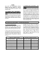
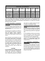
Section 2
START-UP AND OPERATION
STEAM BOILERS
WARNING:
IMPROPER SERVICING AND START-UP OF THIS EQUIPMENT MAY CREATE A
POTENTIAL HAZARD TO EQUIPMENT AND TO OPERATORS OR PERSONS IN THE
BUILDING.
SERVICING AND START-UP MUST BE DONE ONLY BY FULLY TRAINED AND
QUALIFIED PERSONNEL.
CAUTION:
BEFORE DISCONNECTING OR OPENING ANY FUEL LINE, OR BEFORE CLEANING OR REPLACING
PARTS OF ANY KIND, TAKE THE FOLLOWING PRECAUTIONS:
Turn OFF the main fuel shutoff valves, including the pilot gas cock if applicable. If the burner is a multiple
fuel type, shut OFF all fuel supplies.
Turn OFF all electrical disconnects to the burner, boiler and any other equipment or systems electrically
interlocked with the burner or boiler.
All cover plates, enclosures, and guards must be in place at all times except during maintenance and
servicing.
2.1 FIRING RATE ADJUSTMENT - ATMOSPHERIC GAS UNITS
2.1.1 The following procedures must be followed
carefully before putting the boiler in operation.
Failure to do so will present severe hazards to
equipment, operating personnel and building
occupants.
2.1.2 ADJUST PILOT BURNER
Carefully follow the Lighting Instructions in the
boiler manual for the proper adjustment of the
pilot burner. This is absolutely essential before
attempting to adjust the main burner.
2.1.3 ADJUST BOILER INPUT(S)
The boiler input must be adjusted for both
maximum and minimum input values which are
listed on the boiler nameplate. First adjust the
maximum input rating using the method
described in Lighting Instructions in the Boiler
Manual. Refer to the following information for the
adjustment of the minimum input. To determine
the adjustment
which firing rate system is used, see the boiler
Equipment List and Wiring Diagram.
2.1.4 ADJUST BOILER MINIMUM INPUT
After setting the correct Maximum input as
described in the Lighting Instructions, proceed to
adjust the minimum input as outlined below. This
applies only to those boilers which are designed
and equipped for two-stage (High/Low/Off) firing
or Modulation. On those boilers which are
equipped for ON/OFF firing only, no minimum
input adjustment is required. NOTE: the low firing
rate input is adjustable only on boilers equipped
with two-stage or modulating motorized gas
valves (V4055, V9055, or AH4 actuators) or with
motor-operated modulating butterfly gas valves.
The other two-stage firing systems (VR850 or
VR852 combination valves or dual diaphragm
valve type bypass systems) have a nonadjustable minimum input rate.
NOTE
THE LOW FIRE ADJUSTMENT SHOULD
RESULT IN A GAS PRESSURE ON THE
BURNER MANIFOLD EQUAL TO 1" WATER
COLUMN FOR NATURAL GAS AND 3" FOR
PROPANE GAS.
2.1.5 MINIMUM INPUT ADJUSTMENT COMBINATION GAS VALVES (VR850 OR
VR852)
The minimum input on these gas valves is NOT
adjustable. The maximum input must be properly
set as outlined in Lighting Instructions. See the
manufacturer's instructions on the VR850 or
VR852 included in the Boiler Manual for further
information.
2.1.6 MINIMUM INPUT ADJUSTMENT - DUAL
DIAPHRAGM GAS VALVE HIGH/LOW BY-PASS
SYSTEM
The minimum input on this control system is NOT
adjustable. The maximum input must be properly
set as outlined in Lighting Instructions. This
system consists of two V48A (120 volt coil) or two
V88A (24 volts coil) diaphragm gas valves which
are piped in parallel. The minimum input is
controlled by an orifice plug installed in a coupling
in the by-pass piping (low fire valve piping), sized
for approximately 1" w.c. manifold pressure at low
fire natural gas (2" w.c. if propane gas). When the
high fire gas valve is not activated, gas flows only
through the bypass piping. When the high fire gas
valve is activated, gas will flow though both
valves achieving full input.
2.2 FIRING RATE ADJUSTMENT - GAS METER READINGS
2.2.1 CHECKING BURNER INPUT
The burner input rate can be checked by taking
readings from the gas meter. Please note
checking the rate with a meter is the only way to
be sure of input. Manifold readings are only an
approximate value and may vary from unit to unit.
In order to obtain accurate data, there must be no
other appliances using gas from the same meter
while the burner input rate is being checked. The
test hand on the meter should be timed for
several revolutions. The input rate in cubic feet
per hour is
Table 2.2A - Pressure Correction
calculated from this timing. The method is
described in Lighting Instructions. If the meter is
not calibrated for gas temperature and pressure,
correction factors must be applied to determine
correct rate in SCFH (standard cubic feet per
hour). Consult the National Fuel Gas Code (ANSI
Z223.1, NFPA 54) or the local gas utility for
further information. Refer to Table 2.2A for
correction factors for the gas pressure at the
meter. Refer to Table 2.2B for the gas
temperature correction factors.
Table 2.2B - Temperature Correction
Gas Pressure at Meter
Correction Factor
Gas Temp. at Meter
Correction Factor
7" w.c.
1.017
40 F
0.920
14" w.c.
1.034
50 F
0.902
21" w.c.
1.051
60 F
0.885
1 psig
1.061
70 F
0.868
2 psig
1.136
80 F
0.852
5 psig
1.340
90 F
0.836
2.3 SAFETY SHUT-OFF DEVICES (FLAME SUPERVISION)
2.3.1 FLAME SUPERVISORY SYSTEM
The boiler is equipped with a flame supervisory
system, either the Thermocouple type (such as a
combination gas valve or a pilotstat) or electronic
type (such as the RA890, or RM7895). The
purpose of this device is to detect the main or
pilot flame, depending on the type of device, and
control the gas valves accordingly. The device
must be checked for proper operation. See
Lighting Instructions in the Boiler Manual for the
correct procedure. The flame supervisory system
must be tested to assure that it will shut off the
main gas valves in case of a
flame loss. In addition to the information given in
Lighting Instructions, operating sequence and
troubleshooting information may be found in the
manufacturer's instructions in the Boiler Manual.
2.3.2 AUTOMATIC (ELECTRIC) IGNITION
SYSTEMS
On boilers equipped with automatic electrically
ignited pilots, follow the procedures described in
Lighting Instructions and test the controls for
proper operation.
2.4 LIMIT CIRCUIT CUT-OUT TEST
2.4.1 PROTECTIVE DEVICES
All operating and limit controls and low water
cutoffs must be tested for proper operation.
2.4.2
STEAM
PRESSURE
OPERATING
CONTROL
The steam pressure in the boiler is regulated by
the Boiler Operator. This is a pressure control
which senses the steam pressure and turns the
boiler on and off accordingly. This control must be
operationally tested. Adjust the pressure setting
on the control to a pressure less than the boiler
pressure (as shown on the boiler pressure
gauge). The control should turn the boiler off.
Restore the control setting to normal. The boiler
should cycle on.
2.4.3 HIGH LIMIT CONTROL
At least one additional pressure control is
provided as the high limit control. It is set at a
pressure above the operator to act as a back-up
should the operator fail. The high limit control
must be operationally tested. With the boiler
operating, decrease the pressure setting of the
limit control below the current pressure of the
boiler. The boiler should cycle off. Restore the
high limit control setting to normal (pushing rest
button if it is a manual reset type). The boiler
should now cycle on.
2.4.4 LOW WATER CUT-OFF(S)
Most boilers are supplied with a float-operated
primary low water cut-off (and pump control or
water feeder combination) or electric probe type
auxiliary control. These water level controls are
intended to sense (and control) the level of the
water in the boiler. They operate to shut off the
boiler if the water level drops below their sensing
level. The low water cut-off and water level
controls must be operationally tested by manually
lowering the boiler water level (by opening the
boiler blowdown valve for probe controls, and by
opening the control blowdown valve for float type
controls). The boiler should cycle off when the
water level drops below the control point of the
low water cut-off. When the water level is
restored, the boiler should cycle back on.
Depress the manual reset button of devices
which require manual reset in order to restore the
boiler to operation. Carefully read the enclosed
literature on the low water cut-off controls,
particularly installaing, operating and servicing.
2.4.5 COMBINATION LOW WATER CUT-OFF &
FEEDER
The low water cut-off/feeder supplied with some
boiler serves as a low water cut-off (see above)
and also causes make-up water to be added to
the boiler should the water level drop below its
control point.
This type of control must be operationally tested
as for low water cut-offs and also to assure that
the make-up water is introduced as needed.
Carefully read the enclosed literature on the Low
Water Cut-off controls, particularly installing,
operating and servicing.
2.4.6 OTHER CONTROLS
Additional controls as required for the particular
installation may also be provided. Refer to the
literature on these devices included in the Boiler
Manual. All such devices must be operationally
tested to assure reliable operation of the boiler
and system.
2.4.7 BOILER FEED SYSTEM
The boiler feed pump must be operationally
tested to assure that it can provide boiler
feedwater at the pressure and in the amount
needed for safe and reliable boiler operation.
2.4.8 CHEMICAL FEED SYSTEM & SOFTENER
Check the performance of the boiler water
softener and chemical treatment system.
Chemically test the feedwater to be certain it
complies with the recommendations of the
chemical treatment consultant.
2.5 RECOMMENDED DRAFT AND COMBUSTION READINGS
ATMOSPHERIC GAS-FIRED BOILERS
BOILER SERIES
DRAFT AT BOILER
OUTLET
(i.w.c.)
CO2 @ HIGH
FIRE
O2 @
HIGH FIRE
CO
(ppm)
SMOKE
NO.
F
-0.01 TO -0.04
7.5 TO 8.5 %
5.0 TO 7.5 %
< 400
0
CL
-0.02 TO -0.04
7.5 TO 9.0 %
4.8 TO 7.5 %
< 400
0
K
-0.02 TO -0.06
8.0 TO 9.5 %
4.0 TO 6.7 %
< 400
0
FORCED DRAFT GAS FIRED BOILERS
BOILER SERIES
DRAFT AT
BOILER
OUTLET (i.w.c.)
CO2 @
HIGH FIRE
O2 @
HIGH FIRE
CO
(ppm)
SMOKE
NO.
D
-0.01 TO -0.04
7.5 TO 9.5 %
4.0 TO 7.5 %
< 400
0
HED
-0.01 TO -0.04
7.5 TO 9.5 %
4.0 TO 7.5 %
< 400
0
CL
0.0 TO -0.04
8.5 TO 10.0 %
3.2 TO 5.0 %
< 400
0
HECL
0.0 TO -0.06
8.5 TO 10.0 %
3.2 TO 5.0 %
< 400
0
RV & RW
+0.50 TO -0.10
9.0 TO 10.0 %
3.2 TO 5.0 %
< 400
0
AB
+0.25 TO -0.06
9.0 TO 10.0 %
3.2 TO 5.0 %
< 400
0
FORCED DRAFT OIL FIRED BOILERS
BOILER SERIES
DRAFT AT
BOILER
OUTLET (i.w.c.)
CO2 @
HIGH FIRE
O2 @
HIGH FIRE
CO
(ppm)
SMOKE
NO.
D
-0.01 TO -0.04
10.0 TO 12.0 %
4.0 TO 7.2 %
< 400
0
CL
0.0 TO -0.04
10.0 TO 12.0 %
4.0 TO 7.2 %
< 400
0
RV & RW
+0.50 TO -0.10
11.5 TO 12.5 %
3.7 TO 5.0 %
< 400
0
AB
+0.25 TO -0.06
11.5 TO 12.5 %
3.7 TO 5.0 %
< 400
0
NOTE: THE VALUES FOR CO2 AND O2 ARE SHOWN FOR HIGH FIRE ONLY. THE VALUES FOR LOW
FIRE OR MID RANGE WILL GENERALLY BE LOWER, PARTICULARLY FOR ATMOSPHERIC GASFIRED BOILERS. DRAFT SHOULD BE MEASURED APPROXIMATELY 24" FROM TOP OF BOILER,
BEFORE ANY DRAFT CONTROL.
2.5.1 DRAFT ADJUSTMENT - ATMOSPHERIC
GAS BOILERS
Refer to Section 1.8.6 for the adjustment method
for barometric dampers. Adjust the damper so as
to yield a draft which results in values of CO2 and
CO within the allowable limits listed above in the
appropriate table.
Draft adjustments are generally not required for
boilers equipped with draft diverters. The diverter
must
be
installed
without
modification.
Combustion readings are required, however, to
assure that the boiler operation is both safe and
efficient.
Draft measurement should preferably be made
with an inclined tube manometer. If a draft gauge
is not available, check to be sure the flue gases
are being carried up the venting system by
passing a lighted taper or match around the edge
of the draft hood relief opening (or barometric). If
the venting system is operating correctly, the
match flame will be drawn toward the draft hood
relief opening. Otherwise the products of
combustion will tend to push the flame and
extinguish it.
CAUTION
IF THE PRODUCTS OF COMBUSTION ARE
BEING EMITTED INTO THE ROOM (VENTING
SYSTEM NOT OPERATING CORRECTLY),
THE BOILER MUST NOT BE OPERATED
UNTIL PROPER ADJUSTMENTS OR REPAIRS
ARE MADE TO ASSURE ADEQUATE DRAFT
THROUGH THE VENTING SYSTEM.
2.5.2 DRAFT ADJUSTMENT -FORCED DRAFT
BOILERS
Draft adjustments are generally not necessary on
forced draft boilers. The draft must be measured
as part of the start-up procedure. The measured
draft at the boiler flue should fall within the
recommended range specified in the appropriate
table.
On some installations the draft may be excessive
due to a high chimney. In these cases, the draft
should be adjusted within the recommended
range specified in the above appropriate table.
This may be done using a barometric damper, a
restrictor, or a locking quadrant damper. Such
devices must be installed and adjusted by a
qualified technician.
2.5.3
COMBUSTION
ADJUSTMENTS
FORCED DRAFT
Refer to the separate burner manual for the
procedures for burner adjustments. The burner
must be adjusted for smooth lightoff. Combustion
parameters should be within the range specified
in the above appropriate table. In no case should
the level of CO be allowed to exceed the limit
given, and the smoke spot reading must also not
exceed the value shown.
2.6 OPERATING INSTRUCTIONS
2.6.1 FAMILIARIZATION WITH MANUAL(S)
The user of the boiler must familiarize himself
with this manual and the burner manual for forced
draft boilers to be sure he is prepared to operate
and maintain the boiler properly.
2.7 MAINTENANCE SCHEDULE
2.7.1 POSTING SCHEDULE
Post a maintenance schedule in accordance with
the recommendations in this manual. A copy of a
typical schedule is included in this manual.
Section 3
The operating instructions should be kept in the
pocket in the boiler for F Series boilers, or
adjacent to the boiler for all others.
READ THE MANUAL BEFORE ATTEMPTING A
START UP.
CARE AND MAINTENANCE
STEAM BOILERS
•
•
•
•
CAUTION:
The boiler area should be kept free of combustible materials, gasoline and other flammable liquids.
The boiler and venting system must be kept free of obstructions of the air louvers and draft hood
relief openings.
The following procedures must be conducted as outlined to assure safe operation of the boiler.
All cover plates, enclosures, and guards must be in place at all times except during maintenance
and servicing.
3.1 REQUIRED PRECAUTIONS DURING TEMPORARY USE
GENERAL
A boiler is often utilized in new construction to
assist in curing of building components or to
provide temporary heat for the construction crew
or for other purposes during the time the building
is under construction. If precautions are not taken
during this time to protect the boiler, a great deal
of damage can occur before the ultimate owner
takes over the building.
1. Knowledge of burner/boiler operation.
It is the mutual responsibility of the installing
contractor and the boiler owner to consider the
effect of temporary usage on the boiler warranty.
The following should be observed so as to assure
the longevity of the boiler.
4. Notification to the manufacturer (or
manufacturer's agent) to provide start-up services
if the boiler was purchased with start-up by a
factory representative.
OPERATOR SKILLS/RESPONSIBILITIES
During the temporary use period, a single
individual must be assigned responsibility for the
care and operation of the boiler. This person's
responsibility must include, but not be limited to,
the following:
2. Possession and understanding of boiler/burner
operating instruction manual.
3. Assurance that the boiler is fed with only
treated water at all times and that chemical
treatment and blowdown procedures are always
followed.
5. Adherence to all of the start-up procedures
noted in the boiler/burner manual.
6. Considerations of warranty should the boiler be
used for temporary heat without adherence to the
recommended start-up and operating procedures
outlined in the instruction manuals.
3.2 CLEANING THE BOILER AND SYSTEM - NEW SYSTEMS
BOIL OUT PROCEDURE
The internal surfaces of a newly installed boiler
will have oil, grease or other protective coatings
used in manufacturing. Such coatings must be
removed since these coatings lower the heat
transfer rate and could lead to overheating of a
tube and reduce operating efficiency. Before
boiling out procedures may begin, the burner
must be ready for firing. The operator must be
familiar with the procedure outlined in the
boiler/burner operating instruction manuals.
In combination with system contamination,
bacteria may cause objectionable odors,
sometimes resembling natural gas. It is important
to keep these fumes from air intakes which would
distribute them throughout the building. On steam
humidification systems this is especially critical.
Consult your local water treatment chemist for
further information.
CAUTION
The boil out procedure outlined must be
performed by, or under the direct supervision of,
a qualified technician. The chemicals used
present a hazard of burns and physical injury if
mishandled. Always use suitable face mask,
goggles, protective gloves and garments when
handling caustic chemicals. Do not permit the
chemical to come into contact with skin or
clothing. Always follow the safety precautions on
the container's label. Add chemicals slowly and in
small amounts to prevent excessive heat and
agitation. Do not add water to acid. Do not add
water to dry chemical. This will cause splattering
and/or explosion and severe risk of personal
injury.
Boiling out under pressure is not recommended.
If boil out under pressure is required, competent
assistance must be provided.
Your water consultant or water treatment
company will be able to recommend a cleaning or
boil out procedure. In the event that such service
is unavailable or as yet not selected, the following
may be used.
1. The boil out of the boiler and system is neither
difficult nor expensive. The chemicals needed for
cleaning are readily available. Trisodium
phosphate, and sodium hydroxide (lye) are the
most commonly used chemicals. Use only one
type of solution in the system. The amount of
chemical required will vary according to
conditions, but an amount of one pound of
chemical per fifty gallons of water is suggested.
2. Before introducing the solution into the boiler,
an overflow pipe should be attached to the top of
the boiler and routed to a safe point of discharge.
3. Remove all safety valves to ensure that none
of the solution will come into contact with the
valve seats. Use care in removing and reinstalling
valves.
4. All valves in the piping to and from the system
must be closed to prevent the chemical solution
from getting into the system.
5. Gauge glasses must be protected from contact
with the boil out chemicals.
6. Fill the boiler with clean softened water until the
water level reaches the upper header. Then add
the cleaning solution into the upper header. Add
more clean water until the boiler is completely
filled. The water used for this initial fill should be
at room temperature, and must be softened as
noted.
7. After filling, fire the boiler intermittently (at
fire) at a frequency as necessary to hold
boiler solution at boiling point temperature.
NOT PRODUCE STEAM PRESSURE. Boil
water, supervised at all times, for at least
hours.
low
the
DO
the
five
8. After the five hour boil out, begin to add a small
amount of fresh softened water so as to create a
slight overflow of the overflow pipe. This will carry
out impurities which have accumulated at the
water surface. Continue to apply heat and
overflow until the water emitted from the overflow
pipe clears. Then shut off burner.
9. Let the boiler cool to 120 F or less. Then drain
the boiler. Use caution that the water is
discharged with safety.
10. Remove the inspection/cleanout openings in
the boiler upper and lower headers and wash the
waterside surfaces thoroughly using high
pressure water stream.
11.
Inspect the boiler's internal (waterside)
surfaces thoroughly after the procedure. If the
surfaces are not clean, repeat the boil out.
12. After boil out, close all openings. Install relief
valves, gauge glasses and other components as
necessary. Completely fill the boiler with fresh,
softened, ambient temperature water. Fire the
boiler at low fire until water temperature of at least
180 F is reached. This will drive off dissolved
gases.
13. The boiler is now ready to operate.
IMPORTANT
If boiler is not to be operated within 24 hours, a
lay-up procedure is required. Refer to instruction
for lay-up.
3.3 SYSTEM CLEAN OUT
Many boilers have been ruined with system
contaminants such as pipe dope, cutting oil,
metal shavings or chips and other debris which
are left in the piping. If these contaminants are
not removed, they will end up in the boiler.
SYSTEM CLEANING PROCEDURE
For steam systems, the boiler will need to be
connected to the header utilizing steam to purge
the piping and thus push the debris out of the
system. However, at this time all condensate
must be wasted until it runs clear and water
analysis of the condensate indicates that it is free
of contaminants. Steam trap strainers must be
periodically opened and cleaned of any debris
which accumulates.
During this system clean out, the boiler make-up
water must be properly softened and treated. At
the conclusion of the system clean out, the
condensate must be reconnected.
For old or existing steam systems, the installation
process may have jarred debris loose. Following
the boil out of the new boiler, the condensate
should be wasted until it is within proper
guidelines. Check all steam trap strainers to
assure their cleanliness. Refer to the succeeding
section on replacement boiler installations.
3.4 REPLACEMENT BOILER INSTALLATIONS:
PROTECTION AGAINST CORROSION & SEDIMENT
BOILER MUST CONTROL FEED WATER
The water feed to the boiler must be controlled by
the boiler-mounted water level control. It is
unacceptable to use gravity return or to let the
water feed be controlled by a condensate/
receiver/ condensate pump system. The water
feed to the boiler must be controlled:
by a feed pump control which is mounted on
the boiler. This control is to activate the feed
pump on a boiler feed system. It will be
necessary to supply such a system if not already
installed. - OR by an automatic water feeder mounted on the
boiler. This is used only on systems requiring
100% make-up, such as humidification, steam
process, etc.
NOTE
It is not recommended to provide the make-up for
a closed steam heating system to the boiler by
means of a water feeder. It is preferred that
system make-up be connected to the condensate
return tank of a boiler feed system.
A boiler feed system may be used in conjunction
with an existing condensate receiver system by
allowing the receiver system to pump condensate
into the boiler feed system tank.
CLEAN OR REPLACE ALL SYSTEM PIPING
AND HEATING UNITS
Arrange for chemical and mechanical cleaning of
the entire system. A chemical treatment company
should be consulted for the proper means of this
chemical cleaning.
Replace any piping considered to be deteriorated
beyond safe or cleanable condition. Flush the
system clean, being certain to isolate the boiler.
DO NOT FLUSH THE SYSTEM THROUGH THE
BOILER
NOTE: For some old systems, there is a
reluctance to clean the piping because of the
possibility of leaks occurring in badly corroded
lines. Should the customer refuse cleaning, it is
necessary to install filtration equipment. Install
either a fibrous filter or a centrifugal filter in the
boiler return piping. This will collect and remove
sediment from the system. A booster pump may
have to be installed as well to overcome the
additional pressure drop introduced in the line by
the filter. When filling the system, provide
chemical treatment as outlined in Section 3.5.
CAUTION
Failure to properly clean the system or to install
mechanical sediment removal equipment can
result in tube blockage and severe corrosion plus
damage to pumps, controls, and air removal
device.
3.5 BOILER WATER TREATMENT
PURPOSE OF WATER TREATMENT
Water treatment is required for satisfactory
operation of the boiler. It must be devised to
prevent depositing of scale and to prevent
corrosion from acids, oxygen and other such
harmful elements that may be in the water supply.
A qualified water treatment chemist should be
consulted and the water systematically treated.
OBJECTIVES
The basic objectives of water treatment are:
1. Prevent the accumulation of scale and
deposits in the boiler.
2. Remove dissolved gases from the
water.
3. Protect the boiler against corrosion.
4. Maintain the highest possible boiler
fuel efficiency.
5. Decrease the amount of boiler down
time from cleaning.
WATER SOFTENER
It is highly recommended that a zeolite water
softener be used for all make-up to the boiler. It is
intended that this be used in addition to the
chemical treatment of the boiler. Water softening
removes calcium and magnesium, the primary
causes of hard boiler scale.
CONTINUOUS MONITORING REQUIRED
Water treatment should be checked and
maintained whenever the boiler is operating. The
boiler operator should be sure that the boiler is
not operating for long periods without proper
water treatment. Water treatment may vary from
season to season or over a period of time.
Therefore, the water treatment procedure should
be checked not less than four times a year, and
possibly more frequently as the local water
conditions may indicate.
3.6 EXTERNAL "FIRE-SIDE" CLEANING
PURPOSE
Carbon (soot) is an insulator and is corrosive.
The heating surface of a boiler must be kept free
from soot accumulation to keep the boiler
operating at its highest efficiency and to avoid
damage from corrosion.
SOOT REMOVAL
If the yearly inspection of the boiler tube surfaces
reveals a build-up of either soot or rust (usually
due to condensation), the tubes should be
thoroughly brushed. (Tube cleaning brushes are
available from Bryan Steam) To inspect and, if
necessary, clean the tube surfaces and flue
collector, first remove the tube access panels.
Examine the exterior of the tubes for evidence of
soot or rust. Using a flashlight, carefully look
between the tubes. There should be an
unobstructed opening between all tubes, and the
top surfaces of the tube must be free from soot
accumulation. Also inspect the interior of the flue
collector. Brush or vacuum the soot from all
surfaces. Be sure to cover atmospheric burners
with a protective cover during cleaning to prevent
soot from falling into them.
If the buildup of soot is appreciable, the flue gas
venting system must be thoroughly inspected
internally as well, and cleaned as necessary.
IMPORTANT
If either soot or condensation is apparent, a boiler
service technician should be consulted. The
presence of soot indicates poor combustion and
possibly hazardous boiler operation. Failure to do
so may result in fire, explosion potential, or
asphyxiation. A combustion test and burner
adjustments should be undertaken at once.
Rust on the tubes indicates that boiler-operating
temperatures are too low. The set point of the
boiler operating control must be no less than
130 F for natural gas or propane firing, and
170 F for oil fired boilers. Boilers equipped with
outdoor reset control must also follow these
limits.
3.7 SUGGESTED MAINTENANCE SCHEDULE
DAILY
1. Make visual inspection of gauges, monitors, and
indicators and record readings in boiler log.
2. Make visual check of instrument and equipment
settings against factory recommended specifications.
3. Check operation of float type low water cutoffs to
ensure control is functioning. The lower piping
connections of float type level controls should have a
suitable blowdown valve piped into a proper drain. This
valve should be opened periodically to allow any sludge
accumulated in the control to be flushed out. On closed
loop water heating systems this should not be often
required. Consult manufacturer's instructions.
WEEKLY
1. On units equipped with firing rate control, verify that it
is functioning correctly by adjusting control and
observing if input changes accordingly.
2. Make visual inspection of igniter and pilot flame. For
an atmospheric unit, confirm pilot flame is as shown in
this manual (Section 1.9) and that the main burners light
off correctly (smoothly) and that the flame is clean and
normal. For units with a power burner, check pilot flame
signal strength as specified in burner manual.
3. Check pilot and main fuel valves for correct operation.
Open limit switch - make audible and visual check check valve position indicators and check fuel meters, if
supplied.
4. Confirm boiler area is free of combustible materials
and that there is nothing obstructing air openings, draft
hood relief openings, etc.
5. Check combustion safety controls for flame failure
and flame signal strength as specified in manufacturer's
instructions located at the back of this manual for
atmospheric units or in the burner manual for units
equipped with a power burner.
6. Check all limit controls as specified in manufacturer's
manual.
MONTHLY
1. Make visual inspection of linkage and proper
operation of flue, vent, stack, or outlet dampers. Check
draft as specified in Section 2 of this manual.
2. Check float low water cutoff as described above.
3. For those units equipped with a power burner, check
low draft, fan, air pressure and damper position
interlocks as specified in burner manual.
4. Check high and low gas pressure interlocks. Refer to
manufacturers instructions for correct procedure.
5. Check high and low oil pressure interlocks. Refer to
manufacturers instructions for correct procedure.
ANNUALLY
1. Perform leakage tests on pilot and main gas or main
oil fuel valves as specified in manufacturers instructions.
2. Check operating control, high limit, low fire start
control, and low water cutoff as specified in
manufacturers instructions.
3. For units equipped with power burners, check air
atomizing interlock, fuel valve interlock switch, purge
switch, burner position interlock, and fuel changeover
control, as specified in burner manual.
4. The boiler should be checked at least yearly by the
local gas utility company. Particular attention should be
paid to the pilot burner safety devices. The pilot burner
should be checked to ensure that prompt ignition of all
burners occurs as the gas valve opens. Refer to Section
1.9.
5. The flue gas passages and the exterior surfaces of
the boiler tubes should be inspected at least annually.
Any accumulation of soot or debris should be thoroughly
cleaned out.
6. If the yearly inspection of the boiler tube surfaces
reveals a build-up of soot (carbon) or rust, the tubes
surfaces should be thoroughly brushed. Failure to do so
may result in fire or asphyxiation hazards.
7. Check float low water cutoff as described above.
7. The boiler pressure vessel and piping should be
checked annually.
8. Check combustion safety control for pilot turndown
and refractory hold-in as specified in manufacturer's
instructions.
3.8 FLOAT-ACTUATED WATER LEVEL CONTROLS
Inspect float type water level controls for proper
operation. Visually inspect sight glasses for
evidence of scale forming residues. Refer to
section 3.9 for gauge glass maintenance.
On closed steam heating systems, the float low
water cutoff should be blown down by means of
opening a blowdown valve on the lower
connection of the cutoff once per day.
On humidification or
blowdown schedule
recommendation from
maintenance program
the boiler.
process systems, the
should be based on
a water treatment and
specifically designed for
At the annual inspection, all float type level
controls should be disassembled, cleaned and
inspected thoroughly. When re-installed these
controls must be given an operational test.
3.9 WATER GAUGE GLASSES
INSTALLATION
Check with the maintenance supervisor and
engineering for the proper glass to be used.
Compare the box and the glass label or marking
to ascertain that the gauge glass ratings or
temperature and pressure are suitable for use on
the boiler. Use new gaskets when replacing
glass. The gaskets used should be the same type
as those originally supplied with the boiler. Make
certain that the gauge glass valves are properly
aligned.
All bolts and nuts must be free running and well
lubricated, preferably with a graphite type
lubricant. Washers under nuts and bolt heads are
desirable. DO NOT tighten while equipment is in
operation.
MAINTENANCE
Inspect the gauge glass regularly for any signs of
clouding or scratching. In new processes, the
gauge glass should be inspected daily until the
need for replacement becomes apparent. This
will help establish the routine inspection cycle.
The gauge glass should be blown down daily so
as to remove accumulated sediment from the
valves.
INSPECTION
To examine for scratches, shine a bright
concentrated light at about a 45 angle. Anything
that glistens brightly should be inspected closely.
Any scratch which glistens and will catch a
fingernail, or crescent-shaped or star-shaped
mark is cause for replacement. This is because
scratches, corrosion, chips and surface damage
weaken the glass. If inner surface appears cloudy
or roughened, and will not respond to cleaning
procedures, this is evidence of chemical attack. If
severe, this is cause for replacement.
REPLACEMENT OF GLASS
Any glass that has been removed from its
mounting in process boilers, regardless of the
reason for removal, should be discarded and
replaced with a new glass and gaskets. Used
glasses may contain hidden damage and
represent a safety hazard.
Be sure that the replacement glass is suitable for
service conditions.
Protective shields to keep cold air, water, or
falling objects from glass must be replaced.
4.0 IDLE BOILER CARE AND LAY-UP
GENERAL
Corrosion damage to boilers is often the result of
improper lay-up during non-operating periods.
Substantial damage can occur in only a few days
in proper precautions are not taken. This damage
is irreversible and will reduce boiler reliability,
increase maintenance costs and eventually
shorten the useful life of the boiler tubes.
Idle boilers are vulnerable to attack when air
contacts untreated wet metal surfaces. To prevent
corrosion, the boiler metal must be protected by
either keeping the surfaces completely dry or
excluding air from the boiler. Air exclusion is
accomplished either by keeping the boiler
completely full of water (short term lay-up) or filling
the boiler with nitrogen gas (long-term lay-up).
The nitrogen gas prevents air infiltration and does
not react with the metal.
In addition to the corrosion damage that occurs,
the metal particles that are released will form an
insulating scale on the tubes when the boiler is
returned to service. These corrosion products will
accumulate on critical heat transfer areas of the
boiler, increasing the potential for localized
corrosion and over heating.
PRE-OPERATIONAL CLEANING AND LAY-UP
Proper lay-up techniques must be used on an idle
boiler even if it has never been in operation.
Before pre-operational lay-up, the boiler must be
chemically cleaned as outlined in Section 3.2 of
this manual. This is required, as noted in this
section, to remove preservatives, oil and grease
from the tube surfaces. Follow the short term or
long term lay-up procedure as appropriate.
TAKING BOILERS OFF LINE
In operation, boiler water contains suspended
solids which are held in suspension due to water
circulation and the action of treatment chemicals.
Unless care is exercised when draining the boiler,
these suspended solids settle on the tube
surfaces and will air dry to an adherent deposit,
sometimes requiring chemical cleaning to remove.
In addition, these deposits may be misleading
regarding the effectiveness of the chemical
treatment program.
PRE-SHUTDOWN PRECAUTIONS
For a period of three to seven days prior to
shutdown, manual blowdown frequency should be
increased. During this period, the lower
conductivity limit should be below 3500 micromohs per centimeter. The feed of internal
treatment must be increased to maintain a specific
residual concentration. Continuous blowdown
(when used) should be kept to a minimum so the
reduction of solids is achieved by the increased
manual blowdown.
WASHDOWN
As the boiler cannot be washed immediately, the
heat in the boiler may cause baking of residual
sludge. The boiler should not be drained until
cooled enough to prevent this. However, never
leave the boiler filled with water for any extended
period of time without taking measures to prevent
corrosion.
LAY-UP CONSIDERATIONS
There are two basic methods of steam boiler layup: Wet lay up or Dry lay-up. The choice of which
method should be used depends on:
• The possibility that the boiler may need to
be placed in operation on short notice.
• Disposal of lay-up solutions
• Freezing potential
Wet Lay-up is recommended for relatively short
outages, such as seasonal lay-up. This method
has the advantage of allowing the boiler to be
brought on line with short notice. But it can pose
problems if there is any likelihood of freezing.
Dry Lay-up is recommended for longer periods of
boiler shut-down or storage. But it is practical only
if boiler can be drained hot (120 F to 170 F) or if
external drying can be provided.
WET LAY-UP OF STEAM BOILERS - SHORT
TERM
In the wet lay-up procedure, the boiler is to be
filled with chemically treated water and sealed to
prevent air in-leakage. Nitrogen gas under slight
pressure can also be used to displace air and
protect the boiler surfaces from corrosion. The
following steps should be taken for wet lay-up of a
boiler:
1a. Procedure for operational boiler:
At least thirty minutes before the boiler comes off
line, add the following chemicals:
Sodium Sulfite - 0.5 lbs. per 100 gallons water
Polymeric Sludge Dispersant - 0.1 lbs. per 100
gallons water
Caustic Soda - 0.3 lbs. per 100 gallons water
1b. Procedure for idle boiler:
If the boiler has never been on line or has been
out of service for cleaning - Select the highest
quality water available to fill the boiler. Steam
condensate, softened water, filtered fresh water,
and boiler feedwater are generally acceptable for
lay-up. Raw city water is not recommended and
should not be used.
Prepare the chemical solution described in (1a) in
a separate tank. Adhere to the safety precautions
described in Section 3.2 of this manual. Add the
concentrated lay-up solution to the boiler during
the time it is being filled.
After the boiler is filled and the lay-up solution has
been added, the boiler is to be operated for thirty
minutes at low fire to circulate and mix the
chemicals.
2. After filling, the boiler must be closed or
blanked tightly. The power supply to the boiler
must be cut off. Vent all air from the top of the
boiler to allow complete fill with the required
solution. Nitrogen gas at 5 psig may be introduced
though a suitable opening to prevent air inleakage during the lay-up period. An alternative to
the nitrogen gas (see safety precautions under dry
lay-up) is to install a 55 gallon drum or auxiliary
vessel as shown in Figure 3.11A. This is to be
fitted with a cover and filled with properly treated
water. This vessel or drum should be connected
to an available opening in the top of the vessel. Its
purpose is to create a hydrostatic head and to
allow a ready visual check of water level loss or
in-leakage during the lay-up period.
chemical. Then repeat Step. 2. Pay attention to
the maintenance of the valves being used to
isolate the boiler to prevent leakage and resultant
dilution of the lay-up solution.
ALTERNATE METHOD
An alternate wet lay-up method is to pipe clean
continuous blowdown water from a properly
treated boiler into any convenient bottom
connection on the idle boiler, allowing the water to
flow through the boiler and out the top (through
any convenient top opening) to the sewer. This
method will insure a continuous, complete fill with
warm, properly treated water. It also prevents inleakage of air by keeping the boiler slightly
pressurized. It may also provide enough heat to
keep the fireside of the boiler dry and possibly
produce adequate freeze protection.
DRY LAY-UP OF STEAM BOILERS - LONG
TERM
The dry lay-up method recommended requires
that the boiler be drained, dried as completely as
is possible, all opening and valves closed.
Nitrogen gas at 5 psig is introduced to the boiler to
pressurize it and prevent air in-leakage. The
success of the procedure depends on the
thorough drying of the boiler metal surfaces after
draining and the exclusion of air during the lay-up.
CAUTION
Figure 3.11A: WET LAY-UP STATIC HEAD
DRUM
3. During lay-up, test the boiler weekly to assure
the proper levels of sulfite and alkalinity. To do
this, take a sample of the boiler water from the
surface blowdown line or other high point. The
test results should be:
Sodium Sulfite 200 ppm minimum
Phenolphthalein Alkalinity (as CaCO3)
400 ppm minimum
If the tests indicate chemical concentration has
decreased, chemical may be introduced to the
boiler by putting it in the drum shown in Fig.
3.11A. Then lower the boiler water level to
introduced it into the boiler. Then operate the
boiler at low fire to circulate the water and mix the
The use of nitrogen for blanketing is
recommended in both the wet and dry lay-up
procedures. Even though nitrogen in dilute
quantities is non-toxic, it will not support life.
Precautions must be taken before entering
equipment filled with nitrogen for inspections or
any other purposes. These precautions shall be
as follows:
disconnection of nitrogen supply line
complete purging and venting of the equipment
with fresh air
testing oxygen levels inside before any attempt
to enter
all confined entry guidelines applicable to site
must be followed
Appropriate caution signs shall be posted around
the equipment to alert personal that nitrogen
blanketing is in use. A boiler laid up dry must be
tagged with information that the unit is not to be
operated until the boiler is properly refilled.
1. Drain the boiler before the steam pressure falls
to zero. Then pressurize with 5 psig nitrogen gas
through a suitable top opening during draining.
The nitrogen pressure is to be maintained through
draining and subsequent storage.
An alternate method is to completely dry a clean
boil (by blowing hot dry air though the boiler) and
then purge the air from the boiler and pressurize
with 5 psig nitrogen. Be aware that all metal
surfaces which are not completely dry are
vulnerable to corrosion, particularly if oxygen is
present.
2. If a boiler has been down for repairs and is to
be laid up, it should be operated to pressurize with
steam and then drained and pressurized with
nitrogen as in step 1.
3. All connections must be blanked or tightly
closed.
Note: Operating boilers must be removed from
service to minimize adherence of boiler water
suspended solids on boiler metal surfaces. Refer
to previous instructions for boiler washdown.
RETURNING IDLE BOILER TO SERVICE
After wet lay-up
To start an idle boiler after wet lay-up, use the
following procedure:
1. If the boiler was pressurized with nitrogen,
disconnect the nitrogen supply source and vent
the boiler.
2. Using the blowdown valve, drain the boiler
partially and make up with feedwater so as to
dilute the chemical residuals to operating
concentration levels.
3. After the boiler water concentrations and the
water level are returned to proper operating
conditions, the boiler can be started in the normal
manner.
After Dry Lay-Up
To start an idle boiler after dry lay-up, use the
following procedure:
1. Disconnect the nitrogen supply source and vent
the boiler in a safe manner - external to the
building and away from air intakes. Then
thoroughly purge the boiler of nitrogen with dry air.
2. The boiler was to have been cleaned before the
lay up procedure. So it is necessary only to fill the
boiler with properly treated water. Then proceed
with start-up.