1
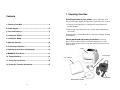
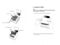
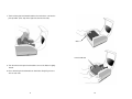
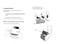
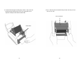
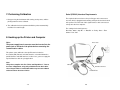
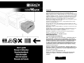
Copyright
This manual is copyrighted with all rights reserved. No portion of this manual may be copied
or reproduced by any means without the prior consent of Brady Worldwide, Inc.
While every precaution has been taken in preparation of this document, Brady assumes no
liability to any party for any loss or damage caused by errors or omissions or by statements
resulting from negligence, accident, or any other cause. Brady further assumes no liability
arising out of the application or use of any product or system described, herein; nor any
liability for incidental or consequential damages arising from the use of this document.
Brady disclaims all warranties of merchantability or fitness for a particular purpose.
Brady reserves the right to make changes without further notice to any product or system
herein to improve reliability, function, or design.
Reproduction of this material, in part or whole, is strictly prohibited without the written
permission of Brady Worldwide, Inc.
Every effort has been made to make this guide as accurate and complete as possible.
Brady Worldwide, Inc. is not responsible for labeling inaccuracies and omissions occurring
during the use of this guide.
This manual is proprietary to Brady Worldwide, Inc. and may be revised from time to time
without notice.
Brady Worldwide, Inc. disclaims any understanding to provide you with revisions, if any.
All brand or product names referenced in this manual are trademarks or registered
trademarks of their respective companies or organizations.
MINIMARKTM and MarkWareTM are registered trademarks of Brady Worldwide, Inc.
Windows is a trademark of the Microsoft Corporation.
© 2005 Brady Worldwide, Inc. All rights reserved.
www.bradyeurope.com
(US and Canada) www.bradyid.com
NOTE: This equipment has been tested and found to comply with the limits for a
Class A digital device, pursuant to part 15 of the FCC Rules. These limits are
designed to provide reasonable protection against harmful interference when the
equipment is operated in a commercial environment. This equipment generates,
uses and can radiate radio frequency energy and, if not installed and used in
accordance with the instruction manual, may cause harmful interference to radio
communications. Operation of this equipment in a residential area is likely to
cause harmful interference in which case the user will be required to correct the
interference at his own expense.
This device complies with part 15 of the FCC Rules. Operation is subject to the
following two conditions: (1) This device may not cause harmful interference, and
(2) this device must accept any interference received, including interference that
may cause undesired operation.
This ISM device complies with Canadian ICES – 001
Caution: Any changes or modifications not expressly approved by the party
responsible for compliance could void the user’s authority to operate the
equipment.
English
1
2
1. Checking Your Box
Contents
Receiving the box of your printer, you are advised to check
first for the possible shipping damage. There are two ways you can do it:
1. Checking Your Box............................................................... 4
2. Power Supply........................................................................ 5
3. Parts and Features ............................................................... 6
4. Loading the Ribbon .............................................................. 8
5. Loading the Media .............................................................. 13
6. Operator Controls............................................................... 18
7. Performing Calibration....................................................... 19
1. Inspect the outer appearances of both the box and the printer for
possible damage.
2. Raise the top cover of the printer to see if the media compartments
are in order.
If damages did occur, immediately file the claim to the shipping company
for settlement.
Having performed the primary inspections, next step,
please check whether you have received the following accessories
together with the printer. If there is any item missing, contact your local
dealer to get it.
Printer
8. Hooking up the Printer and Computer .............................. 19
9. MINIMARK Print Driver....................................................... 21
10. Troubleshooting ............................................................... 23
Parallel Cable
User’s Manual
11. Caring for Your Printer..................................................... 26
12. Reference Technical Information .................................... 27
Power Adapter
MARKWARE CD-ROM
3
4
2. Power Supply
3. Parts and Features
WARNING:
NEVER OPERATE THE PRINTER AND POWER SUPPLY IN
AN AREA WHERE THEY CAN GET WET.
Ready Indicator
1. The Power Adapter has a barrel connector on one end that must be
inserted into the power jack on the back of the printer.
Power Indicator
Top Cover
2. Plug the other end of the cord into an appropriate AC electrical outlet.
3. When plugging the connector into power jack, please leave the power
switch at "O" position and don'
t touch the 36 pin parallel connector.
AC Electrical Outlet
Serial
connector
Power Switch
Power Adapter
USB connector
Power Jack
Barrel Connector
Power Switch
Cutter
Feed Button
Parallel connector
5
6
4. Loading the Ribbon
Note:
This section is not applicable to the direct thermal printing as
a thermal ribbon is not required.
Media Hanger
1. Lift the top cover to expose the media compartment.
Release Levers
Ribbon Pick-up Holder
Ribbon Supply Holder
Thermal Printhead
2. Unlatch the print head module by pushing the two purple release
levers on the sides.
7
8
Media Compartment
4. Unwrap the ribbon roll pack and separate the ribbon roll and the bare
core.
5. Attach the edge of the ribbon on the bare core and wind it a little bit
onto the core.
6. Insert the ribbon roll into the supply holder. (First snap in the right side
and then the left side).
Release Levers
Ribbon Roll
Print Head Module
3. Turn over the print head module to expose the ribbon supply holder.
Ribbon Supply Holder
Bare Core
9
10
7. Turn back the print head module and then insert the bare core into the
pick-up holder. (First snap in the right side, then the left side).
Wheel
Print Head Module
8. Turn the wheel of the print head module to ensure the ribbon is tightly
wound.
9. Press down the print head module on both sides firmly till you hear a
click on each side.
11
12
2. Remove the media hanger.
3. Load the media roll onto the hanger.
4. Unlatch the print head module.
5. Loading the Media
The MINIMARK printer can be operated in two different options:
Cutter On / Cutter Off.
-
In cutter On mode, the printer automatically cuts the label after it
is printed ( 2 modes : cut between each label or cut at the end of
print job).
-
In cutter Off mode, the printer will not cut any label.
The Cutter On/Off modes are set in the Printer Setup in Markware.
Media Hanger
Loading the media (Continuous tape or Die-Cut labels)
1. Lift the top cover to expose the media compartment.
Media Compartment
Ribbon Roll
13
14
5. Lead the label through the media guides and the cutter (under the
bent black plate) with the other hand. The media guide can be
adjusted centrally to fit with different label width.
6. Press down the print head module firmly on both sides till you hear a
click on each side.
Print Head Module
Media Guides
15
16
7. Close the top cover and turn on the printer or press the feed button if
the printer is already on.
6. Operator Controls
Power Switch
Controls printer power
1. On : normal operation – "I" position
2. Off : the power should be turned off before connect or disconnect the
communication cables and power cables – "O" position
Feed Button
Advance the label media to first printing position
1. Press to advance a small length of continuous tape or a label
2. Press to take the printer out of a "pause" condition
Ready Indicator
Show the printers status
1. Green : printer is ready to operate
2. Blinking : printer is paused
Feed Button
Power indicator
Shows the power and error status
1. Off : printer power off
2. Green : printer power on
3. Blinking : error occurs
Note:
The feed button will not drive the printer to cut. The cutting
function can be executed only when the software setting is
ready.
17
18
7. Performing Calibration
1. Keep pressing the feed button while turning on the power, until the
printing motor becomes activated.
2. The calibration has been performed while the printer automatically
feed label for certain length.
Serial (RS-232) Interface Requirements
The required cable must have a nine-pin "D" type male connector on
one end, which is plugged into the mating serial port located on the back
of the printer. The other end of this signal interface cable connects to a
serial port at the host computer.
The settings for the Serial port are :
Baud rate : 9600 – Stop Bit : 1 – Data Bit : 8 – Parity : None – Flow
Control : Xon / Xoff
8. Hooking up the Printer and Computer
Note :
The power supply barrel connector must be inserted into the
power jack on the back of the printer before connecting the
communication cables.
Power Jack
This printer comes with both a nine-pin Electronics Industries
Association (EIA) RS-232 serial data interface, a standard Centronics
parallel interface and USB interface. In either case, you must supply the
required interface cable for your application.
Note :
This printer complies with FCC "Rules and Regulations" , Part 15,
for Class A Equipment, using fully shielded six-foot data cables.
Use of longer cables or unshielded cables may increase radiated
emissions above the Class A limits.
19
USB port
RS-232 Serial Port
Parallel Port
20
Parallel Interface Requirements
The required cable (IEEE 1284-compliant is recommended) must have a
standard 36-pin parallel connector on one end, which is plugged into the
parallel port located on the back of the printer. The other end of the
parallel interface cable connects to the parallel connector on the host
computer.
To minimize electrical noise pickup in the cable:
Keep data cables as short as possible (6ft. [1.83m] recommended).
Do not tightly bundle the data cables with power cords.
Do not tie the data cables to power wire conduits.
Notes :
1. Using Centronics allows for a much higher speed
communication than the use of a serial.
2. It is not necessary to set the switch or send any command to
select the parallel or serial port . The printer can automatically
detect it.
3. A normal USB cable is used if USB port is selected.
Installing MarkWare 3.4 and Higher MINIMARK Print
Driver
1. Install MarkWare if not previously installed.
2. Insert the MarkWare 3.4 and higher MINIMARK CD into your
CD-ROM drive. You can also download the drivers from the Brady web
site at http://www.bradyeurope.com/minimark.
(US and Canada) www.bradyid.com
Note: If the installation CD does not AutoRun, go to Start \
Windows Explorer and then select the drive (for example, D:)
where the MW3.4 and higher CD is located.
3. The Choose Setup Language box displays. Select a language and
click OK.
4. The Choose Printer Port screen displays. Click the communication
port you want to be used from the list and click Next. The print driver will
automatically install. If USB is desired, select USB001.
5. When the print driver installation is completed, a message displays
asking you to restart your computer. Choose Yes or No to restart
9. MINIMARK Print Driver
The MINIMARK print driver is bundled with the Markware 3.4 and higher
CD-ROM (on a separate print driver CD-ROM from Markware 3.5 and
higher). This driver can be installed under Windows 98SE/NT4/2000/XP.
you computer later.
Set the Parameters
After installing the driver, you can follow the path below to set
parameters:
Start
21
Settings
Printers
22
MINIMARK
Properties
Possible Problems
Solutions
Label out
. Supply the label roll out
The parameters include:
Label not installed
. Install the label roll
one of parallel (LPT), serial (COM), USB001 or File.
Label jam
. Recover the jam
Paper size Select the proper size in the menu.
B. Power and Ready LEDs blink alternately
Ports Select the correct port to link with the printer. The port may be
Orientation Set portrait or landscape according to the print direction.
10. Troubleshooting
Power LED
ON
OFF
Ready LED
OFF
ON
Normally, when the printer is in abnormal condition, the power LED will
keep blinking. The printing job and the communication between the host
and printer will stop.
Possible Problems
Ribbon out
Ribbon jam
Ribbon sensor error
To understand the problem, please check both LEDs first:
C. Only the Power LED blinks
A. Power and Ready LEDs blink at the same tempo
Power LED Ready LED
ON
OFF
ON
OFF
Possible Problems
Solutions
Miss-detect the gap . Check the label path
(Die-cut label)
. Check the label sensor
23
Remarks
If you are using
continuous label roll
and run under
Windows, you should
select the continuous
media.
Power LED
ON
OFF
Solutions
Remarks
. Supply the ribbon roll
Not applicable to
direct thermal
. Recover the jam
. Replace the ribbon sensor type.
Ready LED
ON
ON
Possible Problems
Solutions
Serial error
. Check the baud rate
Memory full
. Add the extension
RAM
Cutter failed, or jam at . Check the cutter
cutter
. Recover the jam
Hardware error
Remarks
. Call for service
24
Remarks
Not for Centronics
It occurs when cutter is
activated but connection
cable is disconnected
11. Caring for Your Printer
D. Miscellaneous
The host shows "Printer Time out"
1. Check if the communication cable( parallel, serial or USB) is
connected securely to your parallel, serial or USB port on the PC
and to the connector on the printer at the other end.
2. Check if the printer power is turned on.
Clean the following areas of the printer after 5-8 rolls of continuous tapes
or die-cut labels have been used. In each case, use a cotton bud
dampened with isopropyl alcohol. Do not soak the cotton bud
excessively.
If the power cord is connected, the power switch is at position "I" and
the power LED has still not illuminated, check the fuse inside the
power adapter case.
Cleaning
The data has been sent, but there is no output from the printer. Check
the active printer driver, if MINIMARK printer has been selected.
Vertical streaks in the printout usually indicate a dirty or faulty print
head.
Clean the print head first, if they still persist, replace the print head.
Poor printout quality.
. The ribbon may not be qualified.
. The media may not be qualified.
. Adjust the Darkness ( heat temperature ).
. Slow down the print speed.
. Refer to the next chapter and clean the related spare parts.
Thermal Print Head
Thermal paper and ribbon will release debris on the print head and
degrade printing quality. Clean the print head with isopropyl
alcohol with a cotton bud. Do not touch the heater element with
your fingers. Debris or dirt on the roller should be cleaned with
alcohol.
Paper Sensor
Debris or dirt on the paper sensor will cause a miss-read or
unstable detection of the label gap. Clean with a cotton bud
dampened with alcohol.
Note :
Always switch off the power before cleaning.
Recovery
To continue your print jobs after the abnormal conditions have been
corrected, simply press the panel button or restart the printer. Make sure
that the LED is not blinking and remember to resend your files.
25
26
12. Reference Technical Information
MINIMARK
Specifications
Printing method
Printing
resolution
Printing speed
Printing length
Printing width
Thermal Transfer
203 dpi
(8dots/mm)
1 ~ 4 ips (51~ 102 mm/s)
4" is automatically reduced to 3" if cutter On
1” ~ 45” (25mm ~ 1143mm)
Max 4.1” (104 mm)
2 MB DRAM
2 MB Flash ROM
32 bit RISC microprocessor
Reflective
See - through
LED
indicators x 2
Memory
CPU type
Media sensor
Display
Operation
interface
Communication
interface
Software
Media
Ribbon
Power source
Agency listing
Operation
environment
Cutter
Button x 1
Centronics
RS-232 serial
Bi-USB
(Full Speed)
MARKWARE, version 3.4 and higher
Continuous tapes die-cut labels; Thermal paper or Vinyl /
Polyester
Max width 4.25” (108 mm)
Min width 1.0” (25.4 mm) Thickness .0025”~. 01” (.0635mm
~. 254mm)
Wax, Wax/Resin, Resin (Outside coating ribbon)
Ribbon width –4”
Ribbon length – max 100 M
110/220 VAC ± 10%, 50/60 Hz, external power adapter
CE, UL, CUL, FCC class A, CCC
40ºF ~ 100ºF (4ºC~38ºC) ; 10~90% non condensing
Rotary Cutter
27