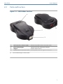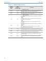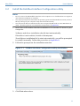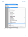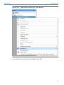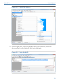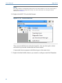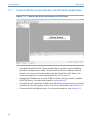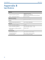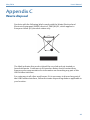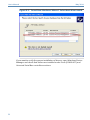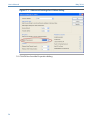
1
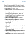
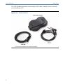
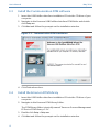
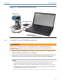
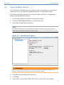
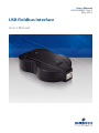
User's Manual
AW7060MNL, Rev 2
May 2014
USB Fieldbus Interface
User's Manual
User's Manual
May 2014
Copyright
© Emerson Process Management, 2014. All rights reserved. Printed in the USA.
Trademarks
The Emerson logo is a trademark and service mark of Emerson Electric Co.
AMS is a mark of one of the Emerson group of companies.
FOUNDATION™ is a mark of the Fieldbus Foundation of Austin, Texas, USA.
Microsoft and Windows are registered trademarks of the Microsoft Corporation in the United
States and/or other countries.
PACTware is a trademark of PACTware Consortium e.V.
All other marks are property of their respective owners.
Contents
Introduction ................................................. 3
Approvals and certifications ........................47
USB Fieldbus Interface .................................. 5
Specifications ............................................. 48
Software installation and device setup ........10
Waste disposal ............................................49
Fieldbus Interface Configuration
utility .......................................................... 16
Install drivers manually ............................... 50
Using with AMS Device Manager .................24
Using with an FDT Frame Application ..........32
Troubleshooting ......................................... 43
2
Disable driver signature enforcement in
Windows 8.0 and 8.1 .................................. 54
Remove pre-release driver versions on a
Windows XP operating system ....................55
May 2014
1
User's Manual
Introduction
This manual guides you in using the USB Fieldbus Interface (interface) to
power and/or configure fieldbus devices. Included here are basic setup,
configuration, and troubleshooting information, as well as guidelines on how
to use the interface with AMS Suite: Intelligent Device Manager and with a
third-party FDT Frame Application.
This manual is divided into the following sections:
• Chapter 1: Introduction – contains safety messages and information
about this manual.
• Chapter 2: USB Fieldbus Interface – contains information about the
interface, its parts, usage, and features.
• Chapter 3: Software installation and device setup – contains system
requirements, software installation instructions, and device setup
information.
• Chapter 4: Fieldbus Interface Configuration utility – contains
information on how to use the utility to power, commission, and/or
configure some parameters of fieldbus devices.
• Chapter 5: Using with AMS Device Manager – contains setup
information and instructions in using the interface with AMS Device
Manager to configure fieldbus devices.
• Chapter 6: Using with an FDT Frame Application – contains setup
information and instructions in using the interface with an FDT Frame
Application to configure fieldbus devices.
• Chapter 7: Troubleshooting – contains solutions to the most common
operating problems.
• Appendix A: Approvals and certifications – contains certifications and
approval information.
• Appendix B: Specifications – contains specifications such as operating
temperature, software, electrical information, and environmental
considerations.
• Appendix C: Waste disposal – contains the interface disposal guidelines.
• Appendix D: Install drivers manually – contains instructions on how to
install drivers manually should they fail to install automatically for
Windows XP operating systems.
• Appendix E: Disable driver signature enforcement in Windows 8.0
and 8.1 – contains information on how to disable driver signature
enforcement on Windows 8.0 and 8.1 operating systems.
• Appendix F: Remove pre-release driver versions on a Windows XP
operating system – contains instructions on how to remove previous
driver versions.
3
User's Manual
1.1
May 2014
Safety message
WARNING!
Do not connect the USB Fieldbus Interface to a live segment (with an active DCS Host and power
supply attached) if the power indicator light on the interface is amber in color. Doing so can disrupt
communications and may compromise automation safety.
4
May 2014
2
User's Manual
USB Fieldbus Interface
Topics covered in this chapter:
• Overview
• Parts and function
• Power modes
2.1
Overview
The USB Fieldbus Interface enables two-way communication between a
computer and fieldbus devices. Its primary function is to allow the setup,
configuration, monitoring, and troubleshooting of fieldbus devices through a
computer.
The interface is fully compatible with all FOUNDATION fieldbus (FF) devices
and is always configured as a "visitor."
Features
Compliant with USB 1.1 and USB 2.0 specifications
Works with standard USB cables
Can detect a Link Active Scheduler (LAS) and will take over as a LAS if it is not present on the
segment
Can be connected to any fieldbus segment containing a FOUNDATION fieldbus device
Has software support for both Device Descriptors (DDs) and FDT Device Type Managers
(DTMs)
It is particularly useful in these plant scenarios:
• Workbench setup and troubleshooting of fieldbus devices
• With a laptop in the field to configure, commission, decommission, or
troubleshoot fieldbus devices
5
User's Manual
May 2014
The USB Fieldbus Interface comes with a USB cable, lead set, user's manual*,
and installation CD*.
Figure 2-1: Box contents
6
May 2014
2.2
User's Manual
Parts and function
Figure 2-2: USB Fieldbus Interface
1
Field connection indicator light (*)
Indicates the fieldbus device connection status
2
Power indicator light (*)
Indicates the power mode of the interface
3
USB port
Enables USB connection
4
Fieldbus device connection socket
Enables fieldbus device or segment connection
(*)
See the Indicator light scenarios table.
7
User's Manual
May 2014
Table 2-1: Indicator light scenarios
Power
indicator
light
Field
connection
indicator light
Scenarios
Normal scenarios
Green
Green
The USB Fieldbus Interface is connected to an externally
powered segment and is able to communicate.
Amber
Green
The USB Fieldbus Interface is providing power to a fieldbus
segment and is able to communicate.
Off
The USB Fieldbus Interface is not connected to a powered
computer.
-ORThe USB Fieldbus Interface is connected to a computer but
the computer power is off.
-ORThe USB FF HSE Server is not running on the connected
computer.
Green
Off
The USB Fieldbus Interface is not connected to a powered
segment.
-ORThe USB Fieldbus Interface is connected to a powered
segment with the wrong polarity.
Off
Green
Amber
Red
The USB Fieldbus Interface is providing power but a short
circuit has been detected on the field connection.
Amber
Off
The USB Fieldbus Interface is providing power and
connected to an already powered fieldbus segment with
reverse polarity.
Amber
Amber
Other scenarios
Off
8
The USB Fieldbus Interface is connected normally to a
powered segment but the USB FF HSE Server is not running.
The USB Fieldbus Interface is providing power to a fieldbus
segment and the load on that segment has exceeded its
limit.
May 2014
2.3
User's Manual
Power modes
The USB Fieldbus Interface is capable of working in two power modes:
• Mode 1 - The interface does not supply power to the connected fieldbus
device or segment. The fieldbus device or segment is powered by an
external source.
Mode 1 is the default.
• Mode 2 - The interface powers the connected fieldbus device or segment
and no external power is needed.
The interface is capable of powering multiple devices on a fieldbus
segment through an external USB hub. It can provide current of up to 85
mA (typically sufficient for three or four fieldbus devices on the same
segment).
You can configure Mode 2 using the Fieldbus Interface Configuration
utility. For more information, see Section 4.2.
WARNING!
Choose only one power mode. Never attempt to use two power sources at the same time. Doing so
can disrupt communications and may compromise automation safety.
9
User's Manual
3
May 2014
Software installation and device setup
Topics covered in this chapter:
• System requirements
• Install the Fieldbus Interface Configuration utility
• Install the Communication DTM software
• Install the Emerson DTM Library
• Setup and connection
• Connect to a live fieldbus segment
Perform software installation and device setup in the following order:
1. Install the Fieldbus Interface Configuration utility.
This allows you to configure the USB Fieldbus Interface and connected
fieldbus devices.
2. Install the Communication DTM software.
This enables DTM support for connected fieldbus devices.
3. Install the Emerson DTM Library.
This allows you to use DTMs associated with Emerson devices through an
FDT Frame Application.
Note
Device DTMs are usually acquired from device suppliers. Contact your device supplier if you
have a non-Emerson device and install the appropriate third-party DTM library.
4. Set up and configure connected fieldbus devices.
3.1
System requirements
Supported operating systems
Windows 8.0 and 8.1
Windows 7 (32- or 64-bit)
Windows XP Home or Professional (32-bit) SP3
Hard disk space
At least 500MB
Hardware
USB 1.1 or USB 2.0 port
10
May 2014
3.2
User's Manual
Install the Fieldbus Interface Configuration utility
Notes
•
Do not connect the USB Fieldbus Interface to the computer or to a fieldbus device or segment
until software installation is complete.
•
You may be prompted to determine the operating system and the Windows version (32-bit or
64-bit) running on your computer. Keep this information handy.
•
You may not be able to install drivers that are not signed by Microsoft on some Windows 8.0
and 8.1 operating systems. To override this requirement, see Appendix E.
1. Insert the USB Fieldbus Interface installation CD into the CD drive of your
computer.
Software and driver installation should start automatically.
If AutoRun is not enabled, double-click setup.exe.
Should driver installation fail to start automatically, you will be prompted
to install it manually. Follow the procedure in Appendix D.
2. Follow the prompts on the installation window.
Figure 3-1: Fieldbus Interface Configuration utility installation
3. Click Finish when done.
11
User's Manual
3.3
May 2014
Install the Communication DTM software
1. Insert the USB Fieldbus Interface installation CD into the CD drive of your
computer.
2. Navigate to the Emerson USB Fieldbus Interface DTM folder and doubleclick Setup.exe.
3. Click Next and follow the prompts on the installation window.
Figure 3-2: Communication DTM installation
4. Click Finish when done.
3.4
Install the Emerson DTM Library
1. Insert the USB Fieldbus Interface installation CD into the CD drive of your
computer.
2. Navigate to the Emerson DTM Library folder.
The DTM library folder is typically named "Emerson Process Management
FF Device DTM Library v1.x.x".
3. Double-click Setup > Setup.exe.
4. Click Next and follow the prompts on the installation window.
12
May 2014
User's Manual
Figure 3-3: Emerson DTM Library installation
5. Click Close when done.
13
User's Manual
3.5
May 2014
Setup and connection
Note
Install the Fieldbus Interface Configuration utility first before setting up and connecting the USB
Fieldbus Interface. For more information, see Section 3.2
1. Connect the USB Fieldbus Interface to the computer using the USB cable
provided.
Driver installation should start automatically.
If automatic driver installation fails, you need to manually install drivers.
For instructions, see Appendix D.
2. Connect the interface to a fieldbus device or to a fieldbus segment using
the field leads.
WARNING!
Do not proceed to the next step if you are connecting to a live (powered) segment. Providing
additional power source to an already powered segment can disrupt communications and may
compromise automation safety.
3. Power the connected fieldbus device or segment.
Connect the fieldbus device or the unpowered segment to an external
power source (Mode 1), or provide power using the Fieldbus Interface
Configuration utility (Mode 2). For more information on the power
modes, see Section 2.3.
14
May 2014
User's Manual
Figure 3-4: Sample benchtop connection
3.6
Connect to a live fieldbus segment
WARNING!
Do not use the Provide Power option on the Fieldbus Interface Configuration utility when
connecting to a live segment. Doing so can disrupt communications and may compromise
automation safety.
1. Make sure the USB Fieldbus Interface is connected to the computer and
that all software and drivers are installed.
2. Plug one end of the field lead to the fieldbus device connection socket of
the interface and connect the other end to the live fieldbus segment.
Notes
• The USB Fieldbus Interface draws current of 10 mA from the segment. Make sure the
segment has enough power and has the capacity to provide this additional current.
• Make sure the lead set is connected to the live fieldbus segment with the correct polarity.
• Commissioning, decommissioning, and changing the device tag/address are not allowed
for fieldbus devices connected to a live segment.
15
User's Manual
4
May 2014
Fieldbus Interface Configuration utility
Topics covered in this chapter:
• Launch the Fieldbus Interface Configuration utility
• Power fieldbus devices
• Commission fieldbus devices
• Decommission fieldbus devices
• Change the device class
• Start or stop the USB FF HSE Server manually
4.1
Launch the Fieldbus Interface Configuration utility
• Click Start > All Programs > Emerson Process Management > USB Fieldbus Interface
> USB Fieldbus Interface.
or
• Double-click the USB Fieldbus Interface desktop shortcut.
This is only available when you have selected the desktop icon option
during software installation.
Note
If no fieldbus device is detected after 30 seconds, this dialog is displayed. Click OK to continue.
Figure 4-1: No device detected dialog
A connected fieldbus device or segment has to be powered by an external
power source or be provided power by the Fieldbus Interface Configuration
utility for it to be detected. For more information, see Section 7.2.
16
May 2014
4.2
User's Manual
Power fieldbus devices
You can power a fieldbus device or segment by connecting it to an external
power source or by using the Fieldbus Interface Configuration utility.
The following steps detail how to use the Fieldbus Interface Configuration
utility to power fieldbus devices.
1. Launch the Fieldbus Interface Configuration utility.
2. Click the USB Fieldbus Interface icon in the tree view.
3. Select the Provide Power check box.
Note
The USB Fieldbus Interface is only capable of providing an output current of up to 85 mA.
Typically, you should not attempt to connect more than three or four fieldbus devices on the
same segment when using the Provide Power option.
Figure 4-2: Provide Power option
WARNING!
Do not use the Provide Power option on a live (already powered) segment. Doing so can
disrupt communications and may compromise automation safety.
4. Click OK to acknowledge the warning.
5. Click Apply.
6. Select Yes to restart the USB FF HSE Server and use the new setting.
17
User's Manual
4.3
May 2014
Commission fieldbus devices
Commissioning sets the fieldbus device address to a valid permanent address
and sets the device tag to a valid string.
Notes
•
You need to commission fieldbus devices first before you can use them with AMS Device
Manager or with an FDT Frame Application.
•
Fieldbus devices on a live segment cannot be commissioned.
1. Launch the Fieldbus Interface Configuration utility.
2. Under the USB Fieldbus Interface icon, select the fieldbus device you
want to configure.
Note
A connected fieldbus device or segment should be powered by an external power source or be
provided power by the Fieldbus Interface Configuration utility for it to be detected.
3. Optionally, select a permanent device address from 20 to 38. Otherwise,
the first available address is assigned.
Note
The utility only accepts device addresses in the range of 20 through 38.
4. Optionally, enter a device tag.
5. Click Commission.
18
May 2014
User's Manual
Figure 4-3: Commission
Note
The commissioning process takes about 1 to 2 minutes to complete.
6. Repeat steps 2 through 5 for each device you want to commission.
4.4
Decommission fieldbus devices
Decommissioning sets the fieldbus device address to a temporary address.
Note
Fieldbus devices on a live segment cannot be decommissioned.
1. Launch the Fieldbus Interface Configuration utility.
2. Under the USB Fieldbus Interface icon, select the fieldbus device you
want to configure.
Note
A connected fieldbus device or segment should be powered by an external power source or be
provided power by the Fieldbus Interface Configuration utility for it to be detected.
3. Click Decommission.
19
User's Manual
May 2014
Figure 4-4: Decommission
4. Determine if the fieldbus device was commissioned on another host,
then select Yes or No.
• If you choose Yes, the decommissioning proceeds.
• If you choose No, you cannot decommission the device.
Decommissioning is not allowed for devices commissioned on
another host.
5. Repeat steps 2 through 4 for each device you want to decommission.
4.5
Change the device class
A connected fieldbus device can be assigned as a Link Master (LM) or as a
basic device. A Link Master contains the LAS functionality that controls
communications on a fieldbus link or segment.
1. Launch the Fieldbus Interface Configuration utility.
2. Under the USB Fieldbus Interface icon, select the fieldbus device you
want to configure.
Note
A connected fieldbus device or segment should be powered by an external power source or be
provided power by the Fieldbus Interface Configuration utility for it to be detected.
3. From the Device Class section, click Read to identify if the fieldbus device
is a Link Master or a basic device.
20
May 2014
User's Manual
Note
Only the device class of a commissioned fieldbus device can be identified. For more
information on commissioning a device, see Section 4.3.
Figure 4-5: Identify the device class
4. Switch to Basic or Link Master from the drop-down menu and click Apply.
21
User's Manual
May 2014
Figure 4-6: Change the device class
5. Click Yes to acknowledge the restart of the device.
6. Click OK to continue.
Note
Changing the device class takes about 1 minute to complete.
4.6
Start or stop the USB FF HSE Server manually
The USB FF HSE Server automatically starts when you launch the Fieldbus
Interface Configuration utility. It is typically not necessary to start or stop the
USB FF HSE Server manually.
1. Launch the Fieldbus Interface Configuration utility.
2. Click the USB FF HSE Server icon in the tree view.
3. Click Start Server or Stop Server.
22
May 2014
User's Manual
Figure 4-7: Start Server/Stop Server
Note
The USB FF HSE Server should be running in order to use the Fieldbus Interface Configuration
utility to power or configure a fieldbus device or segment.
23
User's Manual
5
May 2014
Using with AMS Device Manager
Topics covered in this chapter:
• Add a network component in AMS Device Manager
• Configure fieldbus devices in AMS Device Manager
AMS Device Manager provides a single application for predictive diagnostics,
documentation, calibration management, and device configuration. Using
AMS Device Manager gives you better visibility into the assets in your plant,
resulting in faster startup and increased availability through more costeffective maintenance and improved asset performance.
Contact your Emerson Sales/Support representative for more information on
AMS Device Manager.
5.1
Add a network component in AMS Device Manager
An FF HSE network component has to be present in order to use the USB
Fieldbus Interface with AMS Device Manager.
Notes
•
If there is an existing FF HSE network configured for another fieldbus device, you do not need
to add a new FF HSE network component.
•
You must have an updated license file that includes an HSE license. The HSE license enables
you to add an FF HSE network component in AMS Device Manager.
If you do not yet have an HSE license, contact your Emerson sales representative and place an
order for part number AW7060HSE.
1. Click Start > All Programs > AMS Device Manager > Network Configuration to open
the AMS Device Manager Network Configuration utility.
2. Click Add.
24
May 2014
User's Manual
Figure 5-1: Add a network component
3. Select the FF HSE Network component, and click Install.
25
User's Manual
May 2014
Figure 5-2: Install an FF HSE network component
4. Click Next to proceed.
5. Enter a name for the FF HSE network, and click Next.
26
May 2014
User's Manual
Figure 5-3: Enter a network name
6. Choose to automatically discover FF HSE linking devices or manually
configure IP addresses for FF HSE linking devices.
27
User's Manual
May 2014
Figure 5-4: Configure the network connection
Notes
• Choosing the PC NIC address in the Primary HSE NIC Address field displays the USB Fieldbus
Interface and any local FF HSE interfaces on the network in the AMS Device Manager
hierarchy.
• Choosing the localhost address (127.0.0.1) in the Primary HSE NIC Address field displays
only the USB Fieldbus Interface in the AMS Device Manager hierarchy.
• Manually entering IP addresses displays manually entered FF HSE networks and the USB
Fieldbus Interface in the AMS Device Manager hierarchy.
• The USB Fieldbus Interface does not support FF device alerts.
28
May 2014
User's Manual
7. Click Finish when done.
5.2
Configure fieldbus devices in AMS Device Manager
Note
Commission fieldbus devices first in the Fieldbus Interface Configuration utility before configuring
them in AMS Device Manager. For more information, see Section 4.3.
1. Click Start > All Programs > AMS Device Manager > AMS Device Manager to open
AMS Device Manager.
2. Enter your username and password, and click OK.
3. From the Device Connection or Device Explorer view, right-click the FF
HSE network icon and select Rebuild Hierarchy.
The USB Fieldbus Interface icon then appears under the FF HSE network.
Figure 5-5: USB Fieldbus Interface icon in AMS Device Manager
4.
If you are using the Device Connection View, click the
sign next to the
USB Fieldbus Interface icon to display a list of connected fieldbus devices.
5. If necessary, right-click the USB Fieldbus Interface icon and then scan new
devices.
29
User's Manual
May 2014
Scanning synchronizes the AMS Device Manager database with
connected live devices.
6. Right-click the fieldbus device you want to configure and select from the
context menus.
Figure 5-6: Fieldbus device context menus
30
Configure
Displays configuration parameters that define
the physical attributes and operating
characteristics of the device.
Compare
Lets you compare two configurations of the
device.
Service Tools or
Device Diagnostics
Displays alert conditions. These include
hardware and software malfunctions or
parameters with values beyond the device
specifications.
Overview or
Process Variables
Displays the current output from the device.
May 2014
User's Manual
For more information about the context menus and other AMS Device
Manager functions, refer to AMS Device Manager Books Online.
31
User's Manual
6
May 2014
Using with an FDT Frame Application
Topics covered in this chapter:
• Install an FDT Frame Application
• Update the DTM library
• Configure fieldbus devices in an FDT Frame Application
You can also configure fieldbus devices using third-party FDT Frame
Applications. For the purpose of this document, PACTware is used as an
example. PACTware can be downloaded from multiple sites on the Internet.
6.1
Install an FDT Frame Application
Note
Install the Communication DTM software and the Emerson DTM Library first before installing an
FDT Frame application. For instructions, see Section 3.3 and Section 3.4.
To be able to view DTMs associated with a device, an FDT Frame Application
should be installed. Follow the manufacturer's recommended software
installation instructions.
For the purpose of this document, PACTware is used.
6.2
Update the DTM library
Note
You only need to update the DTM library when a new DTM is recently added.
1. Launch PACTware.
2. Press F3 to show the Device catalog and click Update device catalog.
32
May 2014
User's Manual
Figure 6-1: Update device catalog
3. Click Yes when prompted to create a new PACTware device catalog.
4. Close the device catalog when done.
6.3
Configure fieldbus devices in an FDT Frame Application
Notes
•
Install the Communication DTM software and the DTM Library first before configuring fieldbus
devices in an FDT Frame Application. For more information, see Section 3.3 and Section 3.4.
•
If necessary, update the DTM library. For more information, see Section 6.2.
•
Make sure the USB Fieldbus Interface and fieldbus devices are correctly set up and that the
Fieldbus Interface Configuration utility is installed and running. For more information, see
Section 3.5 and Chapter 4.
1. Launch PACTware.
2. From the Project pane, right-click HOST PC and click Add device.
33
User's Manual
May 2014
Figure 6-2: Project pane
Press F2 to display the Project pane if it is not already displayed.
3. Select Emerson FF HSE Server and click OK.
Figure 6-3: Add the Emerson FF HSE Server
4. Right-click FF HSE Server on the Project pane and click Add device.
34
May 2014
User's Manual
Figure 6-4: FF HSE Server - Add device
5. Select Emerson USB Fieldbus Interface and click OK.
35
User's Manual
May 2014
Figure 6-5: Add the Emerson USB Fieldbus Interface
6. Right-click USB Fieldbus Interface on the Project pane and click Add device.
36
May 2014
User's Manual
Figure 6-6: USB Fieldbus Interface - Add device
7. Select the device you want to add then click OK.
37
User's Manual
May 2014
Figure 6-7: Add device
Only devices with DTMs available and installed appear on the list. For
more information on DTM library installation, see Section 3.4.
Repeat steps 6 and 7 if you want to add more devices to the list.
8. Right-click USB Fieldbus Interface and select Additional functions > Edit DTM
Address.
38
May 2014
User's Manual
Figure 6-8: Edit DTM Address
9. On the right pane, select the fieldbus device from the list, enter the
device address in the Node ID field, and click Apply.
Figure 6-9: Enter Node ID
39
User's Manual
May 2014
Note
The device address and Node ID should match. The device address is set and can be found in
the Fieldbus Interface Configuration utility. For more information on setting the device
address, see Section 4.3.
10. Right-click HOST PC and click Connect.
Figure 6-10: Connect devices
This connects all devices under the host PC. You can also opt to select
each device you want connected and click Connect.
Connected devices appear in bold face type in the menu tree.
11. Right-click the fieldbus device you want to configure and click Parameter.
40
May 2014
User's Manual
Figure 6-11: Parameter
This displays the various parameters you can edit for the device.
12. Configure the parameters of the device.
Note
The parameter display varies and is dependent on the device manufacturer.
41
User's Manual
May 2014
Figure 6-12: Edit device parameters
42
May 2014
7
User's Manual
Troubleshooting
Topics covered in this chapter:
• Fieldbus device not responding in AMS Device Manager
• Fieldbus device not detected in Fieldbus Interface Configuration utility
• Cannot edit device parameters in FDT Frame Application
7.1
Fieldbus device not responding in AMS Device Manager
In order to configure a fieldbus device in AMS Device Manager, you must first
commission the device in the Fieldbus Interface Configuration utility. For
more information on commissioning a device, see Section 4.3.
Uncommissioned devices are seen in AMS Device Manager as having the
(non-responding device) icon and are characterized by an empty device tag
or by the device default address.
Figure 7-1: Uncommissioned device in AMS Device Manager
43
User's Manual
May 2014
Commissioned fieldbus devices appear with their own icons in AMS Device
Manager and are characterized by a valid permanent address or by a valid
device string.
Figure 7-2: Commissioned device in AMS Device Manager
7.2
Fieldbus device not detected in Fieldbus Interface
Configuration utility
The Fieldbus Interface Configuration utility immediately detects connected
fieldbus devices. If 30 seconds have elapsed and no device is detected, the
following dialog is displayed.
44
May 2014
User's Manual
Figure 7-3: No device detected dialog
Click OK and check for the following:
• Make sure the fieldbus device or segment is powered either by an external
source or by the USB Fieldbus Interface. For more information, see
Section 2.3.
• Make sure drivers are installed and that the hardware is ready for use.
If automatic driver installation fails, install drivers manually. For more
information, see Appendix D.
• Check that there are no loose connections and that the USB cable does not
exceed 2 meters in length.
• Make sure the USB FF HSE Server is running.
45
User's Manual
7.3
May 2014
Cannot edit device parameters in FDT Frame Application
Figure 7-4: Cannot edit device parameters in PACTware
• Check the Node ID in PACTware and the Device Address in the Fieldbus
Interface Configuration utility. The Node ID and Device Address should
match. You may need to manually enter the Node ID in PACTware. For
more information on entering the Node ID, see Section 6.3.
• Update the DTM library. If a new DTM is added, you may need to update
the DTM library. For more information, see Section 6.2.
• Check physical connections. Make sure all devices are properly connected
and have access to a power source. For more information, see Section 3.5.
• Commission the fieldbus device. For more information, see Section 4.3.
46
May 2014
User's Manual
Appendix A
Approvals and certifications
Fieldbus Foundation Communication
FF Physical Layer Specification (IEC 61158-2)
FF Physical Layer Conformance Test (FF830)
CE
EN 61326-1-2006, Radiated Emissions Class B, Basic Immunity Test
Requirements.
ETL (US and Canada)
Conforms to ANSI/UL STD 60950-1; Certified to CAN/CSA STD C22.2 NO.
60950-1.
IC
This Class B digital apparatus complies with Canadian ICES-003, Issue 4:2004.
Cet appareil numérique de la classe B est conforme à la norme NMB-003 du
Canada.
FCC
This device complies with Part 15 Subpart B of the FCC Rules. Operation is
subject to the following conditions:
47 CFR, Part 15:2009, §15.107, §15.109, Class B
Any modifications made to this device that are not approved by Emerson
Process Management may void the authority granted to the user by the FCC
to operate this equipment.
47
User's Manual
May 2014
Appendix B
Specifications
Software
Supported operating systems
Windows 8.0 and 8.1
Windows 7 (32- or 64-bit)
Windows XP Home or Professional (32-bit) SP3
USB 1.1 and USB 2.0 interface
Drivers included
Application software
AMS Device Manager
Version 11.5 or later
License
AMS Device Manager HSE license
Part number AW7060HSE
Electrical
Power consumption (Mode 1)
≤ 0.2 W
Power consumption (Mode 2)
at 85 mA output current ≤ 2.5 W
at 50 mA output current ≤ 1.7 W
Power supply to a fieldbus segment
(in Mode 2)
85 mA at 10V
Environmental
48
Operating temperature
-20 °C to 60 °C (-4 °F to 140 °F)
Storage temperature
-40 °C to 85 °C (-40 °F to 185 °F)
Storage humidity
0 to 95% relative humidity
May 2014
User's Manual
Appendix C
Waste disposal
Products with the following label comply with the Waste Electrical and
Electronic Equipment (WEEE) directive, 2002/96/EC, which applies to
European Union (EU) member states only.
The label indicates this product should be recycled and not treated as
household waste. Customers in EU member states should contact their
Emerson sales representative for information on discarding any part of the
USB Fieldbus Interface.
For customers in all other world areas, if it is necessary to discard any part of
the USB Fieldbus Interface, follow the waste disposal regulations applicable in
your location.
49
User's Manual
May 2014
Appendix D
Install drivers manually
Notes
•
If you have previously installed a pre-release version of drivers, follow the procedure in
Appendix F first before installing new drivers manually.
•
The following procedure only applies to Windows XP operating systems. On Windows 7
operating systems, drivers are automatically installed.
•
There are two drivers that have to be installed manually; one for ports and another for USB
controllers. You need to complete the driver installation on the Found New Hardware Wizard
twice to install both drivers.
1. Connect the USB Fieldbus Interface to the computer using the USB cable
provided.
This facilitates manual installation of drivers through the Found New
Hardware Wizard.
2. From the Found New Hardware Wizard, select the No, not this time option
and click Next.
3. Select the Install from a list or specific location (Advanced) option and click Next.
4. Select the Search for the best driver in these locations option and select the
Include this location in the search check box.
50
May 2014
User's Manual
Figure D-1: Found New Hardware Wizard - Select driver location
5. Browse to where the drivers are located and click Next.
The drivers are typically in
C:\Program Files\Emerson Process Management\USB Fieldbus Interface
\Drivers.
6. If a Windows Logo compatibility warning is displayed, click Continue
Anyway to continue the driver installation.
The wizard installs the driver.
7. Click Finish to close the wizard and start the second driver installation.
After closing, the Found New Hardware Wizard opens again to install the
second driver.
8. Repeat steps 2 through 7 to complete the second driver installation.
Note
For the second driver installation, you may be prompted to select the driver that best matches
the connected USB Fieldbus Interface. This happens when you have previously installed a prerelease version of the driver. Always select the second entry on the dialog, then click Next.
51
User's Manual
May 2014
Figure D-2: Found New Hardware Wizard - Select best driver match
If you want to verify the proper installation of drivers, open Windows Device
Manager and check that drivers are installed under Ports (COM & LPT) and
Universal Serial Bus controllers sections.
52
May 2014
User's Manual
Figure D-3: Windows Device Manager
53
User's Manual
May 2014
Appendix E
Disable driver signature enforcement in Windows
8.0 and 8.1
1. Open the Windows 8 Charms bar.
2. Click Settings > Change PC settings.
3. From the PC Settings window, select General on the left panel.
4. On the right panel, locate Advanced startup and select Restart now.
5. From the Choose an option menu, select Troubleshoot.
6. From the Troubleshoot menu, select Advanced options.
7. From the Advanced options menu, select Startup Settings.
8. Click Restart and select Disable driver signature enforcement.
54
May 2014
User's Manual
Appendix F
Remove pre-release driver versions on a Windows
XP operating system
1. Click Start > Control Panel > Add or Remove Programs.
2. Select 770 USB Serial Converter Drivers from the list, and then click Change/
Remove.
If 770 USB Serial Converter Drivers is not on the list, proceed to Step 4.
3. Follow the prompts on the uninstallation window, then click Finish.
4. If necessary, uninstall the drivers using Windows Device Manager:
a. Launch Windows Device Manager (Start > Run, type devmgmt.msc, and
click OK).
b. Expand Ports (COM & LPT).
c. Connect the USB Fieldbus Interface to the computer through the USB
port and wait a few seconds to see if 770 Fieldbus Interface (COMxx)
appears on the list. If it does not, proceed to Step 5.
d. Right-click 770 Fieldbus Interface (COMxx), and select Uninstall.
e. Click OK to confirm the driver removal.
f.
Expand Universal Serial Bus controllers, right-click 770 Fieldbus Interface,
and select Uninstall.
g. Click OK to confirm the driver removal.
5. After removing previous driver versions, install current drivers manually.
Follow the procedure in Appendix D.
6. After installing current drivers, open Windows Device Manager.
7. Expand Ports (COM & LPT), right-click 770 Fieldbus Interface (COMxx), and
select Properties.
8. From the Port Settings tab, select Advanced.
9. From the BM Options section, set the Latency Timer value to 1 and click
OK.
55
User's Manual
May 2014
Figure F-1: Advanced Settings for COMxx dialog
10. Click OK to close the Properties dialog.
56
May 2014
User's Manual
Index
A
not responding in AMS Device Manager,
troubleshooting 43
AMS Device Manager
providing power 17
adding network component 24
setting device address 18
using to configure fieldbus devices 29
setting device tag 18
setup and connection 14
C
setup and connection, live segment 15
change the device class 20
Fieldbus Interface Configuration utility
commission fieldbus devices 18
installing 11
Communication DTM installation 12
launching 16
configure fieldbus devices
starting/stopping HSE server manually 22
using AMS Device Manager 29
using PACTware 33
connect to live fieldbus segment 15
contents of box 5
H
hard disk space requirement 10
I
D
decommission fieldbus devices 19
device class, changing 20
drivers
automatic installation 11
disable signature enforcement, Windows 8 54
installing manually 50
indicator light status 7
install Communication DTM 12
install drivers manually 50
install Emerson DTM Library 12
install FDT Frame Application 32
install Fieldbus Interface Configuration utility 11
DTM library, installation 12
L
F
launch the utility 16
features 5
FF HSE network component
adding 24
Link Active Scheduler (LAS) 20
Link Master 20
live segment connection 15
field connection indicator light status 7
fieldbus device
basic device 20
cannot edit device parameters 46
changing device class 20
commissioning 18
O
operating systems, supported 10
overview 5
configuring, using AMS Device Manager 29
P
configuring, using PACTware 33
PACTware
decommissioning 19
Link Master 20
update device catalog 32
usage 33
live segment connection and setup 15
PACTware usage 33
not detected in utility, troubleshooting 44
parts and function 7
57
User's Manual
power indicator light status 7
power modes 9
Provide Power 17
May 2014
T
troubleshooting
cannot edit device parameters, PACTware 46
fieldbus device not detected in utility 44
R
fieldbus device not responding in AMS Device
Manager 43
remove pre-release driver versions 55
U
S
setup and connection
benchtop/segment connection 14
live segment connection 15
system requirements 10
58
update device catalog 32
USB FF HSE Server
starting, stopping 22
User's Manual
Part Number: AW7060MNL, rev. 2
May 2014
Emerson Process Management
12001 Technology Drive
Eden Prairie, MN 55344 USA
T 1(952)828-3633
F 1(952)828-3006
www.EmersonProcess.com
©2014, Emerson Process Management
The contents of this publication are presented for
informational purposes only, and while every effort
has been made to ensure their accuracy, they are
not to be construed as warranties or guarantees,
express or implied, regarding the products or
services described herein or their use or
applicability. All sales are governed by our terms and
conditions, which are available on request. We
reserve the right to modify or improve the designs
or specifications of our products at any time without
notice.
All rights reserved. The Emerson logo is a trademark
and service mark of Emerson Electric Co. All other
marks are property of their respective owners.
AW7060MNL, printed in USA/05-2014