1
DS+65, DS+650 Projectors
RS232
LAN
and
communication protocol
DS+65, DS+650 RS232 and LAN Technical Reference Information
020-000056-02 Rev. 1 (08-2009)
TABLE OF CONTENT
2
1
REVISION HISTORY
4
2
SETTING UP LAN COMMUNICATION
5
2.1
SETTING THE IP ADDRESS
5
2.2
CONNECTING TO THE PROJECTOR
6
3
HOW TO USE THE PROJECTORS LAN FUNCTIONALITY
7
4
SETTING UP RS232 COMMUNICATION
8
4.1
CONNECT TO THE PROJECTOR
8
4.2
RS232 COMMUNICATION PARAMETERS
8
5
SEND AND RECEIVE BINARY PACKETS
8
5.1
ABOUT THE PROTOCOL
8
5.2
SET_OPERATIONS
8
5.3
GET_OPERATIONS
8
5.4
INCREMENT_ AND DECREMENT_OPERATIONS
9
5.5
EXECUTE_OPERATIONS
9
5.6
DESCRIPTOR_OPERATIONS
9
5.7
EXAMPLE OF SETTING PROTOCOL PARAMETERS AND SENDING A COMMAND IN CMD WINDOW
9
5.8
OSD FEEDBACK
9
6
SEND AND RECEIVE ASCII COMMANDS
10
6.1
OVERVIEW
10
6.2
MESSAGE BODY
10
6.3
MNEMONIC
10
6.4
MODIFIER
11
6.5
ADDRESSING
11
6.6
ACKNOWLEDGE/RESPONSE
11
6.7
SUPPORTED COMMANDS
12
6.8
EXAMPLES
16
6.9
AMX/CRESTON
20
6.10
TRUTH-TABLES FOR ABS-VALUES
20
DS+65, DS+650 RS232 and LAN Technical Reference Information
020-000056-02 Rev. 1 (08-2009)
APPENDIX
A, BINARY OPERATION PACKET TYPE
21
A.1
OPERATION PACKET TYPE
21
A.2
OPERATION PACKET PAYLOAD FORMAT
21
B, BINARY PACKETS IN HEXADECIMAL VALUES
22
APPENDIX
APPENDIX
C, RS232 DAISY CHAINING
28
C.1
ABOUT THE PROTOCOL
28
C.2
ADDRESS MODES
28
C.2.1 AUTO ADDRESS MODE
28
C.2.2 FIXED ADDRESS MODE
28
C.2.3 BROADCAST
28
C.3
BAUD RATE
28
C.4
SPECIAL SHORT MESSAGES
29
C.5
EXAMPLES
29
APPENDIX
D, ADJUSTING CUSTOM COLOR TEMP USING RS232
20
D.1
CHOOSE “CUSTOM COLOR TEMP”
20
D.2
ADJUST THE COLOR TEMPERATURE BY USING THE INCREMENT / DECREMENT OPERATIONS:
20
E, TRUTH TABLES
32
E.1
OSD WARNING ON
32
E.2
LAMP IGNITION STATES
32
E.3
THERMAL MONITOR STATES
32
E.4
LAMP ON STATE S
32
APPENDIX
DS+65, DS+650 RS232 and LAN Technical Reference Information
020-000056-02 Rev. 1 (08-2009)
3
1 REVISION HISTORY
4
Document
Rev
Release Date
Revised
LAN and RS-232 communication protocol and command set
1.0
15/02/06
Initial
Owner
DS+65, DS+650 RS232 and LAN Technical Reference Information
020-000056-02 Rev. 1 (08-2009)
2 SETTING UP LAN COMMUNICATION
The projector is shipped with a set of default settings, these are as follows:
Description
Value
IP address
192.168.1.90
Subnet mask
255.255.255.0
Default gateway
192.168.1.1
TCP port
1025
UDP port
1225
Username
admin
Password
admin
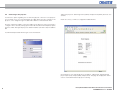
2. Doubleclick on the network connection that represents your LAN, select “properties”,
then doubleclick “Internet Protocol (TCP/IP).
Before you connect the projector to your LAN make sure that the IP address 192.168.1.90
is not already in use. If you need to change it, you have to make sure that the computer you
use is on the same subnet. This means that the computer need to have an IP address in
the range from 192.168.1.1 to 192.168.1.254.
2.1
Setting the IP address
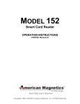
If you need to change the computers IP address, follow these steps:
3. This will take you to a screen where you can set the computers IP address:
Set the IP address and click OK on this and the previous dialog when you’re done.
1. Right click on “Network Neighborhood” / “My Network Places” on your computer, and
then select “Properties”.
DS+65, DS+650 RS232 and LAN Technical Reference Information
020-000056-02 Rev. 1 (08-2009)
5
2.2
Connecting to the projector
You have two options regarding how to make the physical connection to the projector.
You can either use a crossover twisted pair (TP) cabel directly from the computer to the
projector, or two straight-through TP cables with a HUB or a switch between them.
Type in the projectors default login name (admin) and password (admin), both are case
sensitive.
If both are correct, you will se a configuration website like this:
Now the computer should be on the same subnet as the projector, and you are ready to
configure it. This is done by starting up an internet browser, like Internet Explorer, Opera,
Firefox or similar. Then type the projectors default IP address (192.168.1.90) in the address
bar.
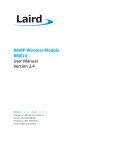
You will then be presented with the login screen shown below:
On this page you can setup the projectors IP address, subnet mask, default gateway,
projector port (TCP), rimi port (UDP), and password. This page also displays the current
version of network firmware the projector is running.
6
DS+65, DS+650 RS232 and LAN Technical Reference Information
020-000056-02 Rev. 1 (08-2009)
3 HOW TO USE THE PROJECTORS LAN FUNCTIONALITY
Once the projector is setup correctly and connected to the LAN, it’s ready to receive
commands. The LAN commands is exactly the same as for RS232 control, although you
may have to pass on the commands to the projector with a different application.
To send an eOperation to the projector, select
”Transfer” and then ”Send Text File...”.
HyperTerminal that comes with Windows, can be used for this.
- Start up HyperTerminal, click ”File” and
then ”New Connection”. Give it a name
and press OK. You will then see this dialog, here you choose TCP/IP (Winsock).
You will then be presented with a dialog which you can choose the file you want to transfer. Choose your command, click ”Open”, and the command will be transfered.
- Now type in the projectors IP address in
the ”Host address:” field, and the projectors TCP port in the ”Port number:” field.
Press OK when you’re done.
Other network options:
As you can see from the default settings table, the projectors also support commands over
the UDP protocol. HyperTerminal doesn’t support UDP but there are other applications like
the ones from SimpleComTools.
There is also quite easy to integrate this functionality if you are designing an application
yourself.
With a Crestron, AMX and other control system you now have the option to control the
projector via Ethernet in addition to RS232 using the same command set.
DS+65, DS+650 RS232 and LAN Technical Reference Information
020-000056-02 Rev. 1 (08-2009)
7
5 SEND AND RECEIVE BINARY PACKETS
4 SETTING UP RS232 COMMUNICATION
This section applies to single projector control with no address information. Please, refer
to Appendix B for detailed information about RS232 daisy-chaining.
4
ESTABLISH COMMUNICATION
The projector may be controlled either through the LAN or the RS232 interfaces. Both
interfaces can not be used at the same time. Select between LAN or RS232 control in the
menus system (se the projector user guide for further information).
4.1
Connect to the projector
Connect the projector and host using a standard serial cable with 9-pin female to the host,
and 9-pin male to the projector. Pin 2 connects to pin 2, pin 3 connects to pin 3 and pin 5
connects to pin 5.
5.1
About the protocol
The RS232 protocol is a binary protocol where each command is a series of 32 bytes in
one packet. See Appendix A for command structure. The tables in appendix B have one
row for each command.
The packet consists of a header with 7 bytes, and the packet payload, 11 bytes (see appendix A). It is important to complete the packet with an additional 14 bytes of padding,
so that the total packet size reaches 32 bytes.
The projectors can be daisy-chained using RS232. Please, refer to Appendix C for detailed information about RS232 daisy-chaining.
The bytes are numbered 1 through 32. Byte 1 is sent first, byte 32 last. Some columns in
Appendix B show the value to be sent for several consecutive bytes. These are typically
indicated by a range, ie. 14 - 16. This means that bytes 14-16 all have the same value.
4.2
The protocol allows for both SET and GET operations. To utilize GET operations the host
needs a routine for receiving and interpreting incoming packets.
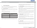
RS232 Communication parameters
Parameter
Data
Baud rate
4800, 9600, 19200
Parity
N
Databits
8
Stopbits
1
Flowcontrol
None
Table 1: RS232 parameters
Baud rate is configurable from the projector’s menu system. Default baud rate is 19200.
5.2
SET_operations
SET_operations are used to force the projector into different modes, like setting brightness and contrast setting, switching between sources, etc.
As seen in Appendix B, each packet is a series of 32 bytes. To control the projector,
simply send the desired packet to the serial port. (An example of how to do this from a
DOS-window is provided in chapter 5.7)
After receiving a packet and executing the operation, the projector will immediately send
a packet in return. The returned packet will contain a PAK (0x1E) (PAK = Packet Acknowledge), followed by the initial SET_operation sent from the host. Total packet size is 33
bytes.
5.3
GET_operations
GET_operations are used to acquire data or status from the projector, such as lamp usage hours, total on time, etc.
A response to a successful GET_operation consists of a PAK (0x1E) followed by the initial
GET_operation sent from the host. The requested value resides as a WORD in byte 17
(low byte) and byte 18 (high byte). Total packet size is 33 bytes.
8
DS+65, DS+650 RS232 and LAN Technical Reference Information
020-000056-02 Rev. 1 (08-2009)
5.4
INCREMENT_ and DECREMENT_operations
These operations are used when you want to increment or decrement the excisting value.
This returns, when successful, an acknowledgement as described in chapter 5.2 ,
and turns the projector on.
The response consists of a PAK (0x1E) followed by the initial operation sent, except for
byte 11, which carries an operation validation code, 0x01. Total packet size is 33 bytes.
5.8
OSD feedback
RS232 control commands will not produce any OSD feedback. Only keypad and IR
remote control will produce OSD feedback.
5.5
EXECUTE_operations
An EXECUTE_operation triggers a pre-programmed algorithm in the firmware to execute
a certain chain of events. The EXECUTE_operation does not contain any parameters to
indicate a desired value, but simply executes the algorithm assigned to it.
The response is equal to that of the INCREMENT/DECREMENT_operations (see 5.4).
5.6
DESCRIPTOR_operations
To aquire the valid range of an operation, set byte 8 (operation type) to 7 (DESCRIPTOR)
fill in the operation number and send the packet. A successful response will consist of
PAK (0x1E), followed by the standard 32 bytes.
5.7
Example of setting protocol parameters and
sending a command in CMD window
Setting up the COM port, and sending a “poweron” command, where “poweron” is simply a binary-file with the appropriate packet for turning the projector on:
DS+65, DS+650 RS232 and LAN Technical Reference Information
020-000056-02 Rev. 1 (08-2009)
9
6
SEND AND RECEIVE ASCII COMMANDS
6.1
Overview
The protocol exists in parallel with the already existing 32/33-byte protocol.
The protocol has the following definition:
<HEADER>
[SEPARATOR]
ADDRESS
[SEPARATOR]
MESSAGE
BODY
1 byte
1 byte
1-3 bytes
1 byte
N bytes
Field
Description
Comment
<HEADER>
ASCII character ‘:’
Required
Separator
ASCII character ‘space’
Optional
Address
1-3 bytes address
Optional
6.2
Message body
The message body structure is as follows:
MNEMONIC
[SEPARATOR]
[MODIFIER]
[SEPARATOR]
VALUES
CR
4 byte
1 byte
1 or 2 bytes
1 byte
N bytes
1 byte
Field
Description
Comment
Mnemonic
4 bytes key identifier,
not case sensitive
Required
Modifer
Single char symbol
Optional
Values
1-3 bytes address
Optional
TERM
Termination char 0x0D (CR)
Required
6.3
MNEMONIC
The Mnemonic is 4 bytes key identifier, know as the ASCII command.
Example: POWR, SABS, IVGA
10
DS+65, DS+650 RS232 and LAN Technical Reference Information
020-000056-02 Rev. 1 (08-2009)
6.4
Modifier
R
Relative change. Value given will be relative to the existing value
A
Request an acknowledge. This modifier is the only that might be applied together with another modifier. It can be
used to read back the result of the command.
?
? – current
?M – max
?N – min
6.5
Addressing
The same address mechanisms as for the binary protocol is supported in the ASCII protocol.
6.6
Acknowledge/Response
Acknowledge is optional and ON by default. Auto acknowledge can be turned on and off with ECHO commad. Also turned activated on a per command basis using modifier A.
ACK
ADDRESS
SEP
COMMAND
SEP
VALUE
TERM.
1 byte
3 bytes
1 byte
4 bytes
1 byte
6 bytes
1 byte
Field
Description
Comment
ACK
ASCII character ‘%’
Always
SEP
ASCII space
Always
VALUE
6 bytes return value
Always
TERM
Termination char 0x0D (CR)
Always
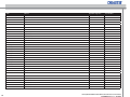
6.7
SUPPORTED COMMANDS
Modifiers
A
Request acknowledge
?
Get current value
?M
Get MAX value
?N
Get MIN value
R
Relative set
DS+65, DS+650 RS232 and LAN Technical Reference Information
020-000056-02 Rev. 1 (08-2009)
11
ASCII
Function
Operations supported
Legal modifiers
AUTO
Execute auto adjust
Execute
A
DPMS 0
DMPS Off
Get, Set
A, ?
DPMS 1
DPMS On
Get, Set
A, ?
DVST 0
DVI Setup OFF (BTB/WTW)
Get, Set
A, ?
DVST 1
DVI Setup ON
Get, Set
A, ?
FCRE
Factory Reset
Execute
A
FRZE 0
Freeze Frame Off
Get, Set
A, ?
FRZE 1
Freeze Frame On
Get, Set
A, ?
DESK
Select Orientation Desktop Front
Get, Set
A, ?
CEIL
Select Orientation Ceiling Front
Get, Set
A, ?
RDES
Select Orientation Desktop Rear
Get, Set
A, ?
RCEI
Select Orientation Rear Ceiling
Get, Set
A, ?
ORIE [0-3] See section 10
Select orientation abs value
Get, Set
A, R, ?, ?M, ?N
IR01 0
IR Sensor front, off
Get, Set
A, ?
IR01 1
IR Sensor front, on
Get, Set
A, ?
IR02 0
IR Sensor rear right, off
Get, Set
A, ?
IR02 1
IR Sensor rear right, on
Get, Set
A, ?
IR03 0
IR Sensor rear left, off
Get, Set
A, ?
IR03 1
IR Sensor rear left, on
Get, Set
A, ?
BKBK
Select Splash/Background Logo/Black
Get, Set
A, ?
LGLG
Select Splash/Background Logo
Get, Set
A, ?
LGBL
Select Splash/Background Blue
Get, Set
A, ?
LGWH
Select Splash/Background White
Get, Set
A, ?
LGBK
Select Splash/Background Black
Get, Set
A, ?
OSDC 1
OSD On
Get, Set
A, ?
OSDC 0
OSD Off
Get, Set
A, ?
GENERAL CONTROL:
12
DS+65, DS+650 RS232 and LAN Technical Reference Information
020-000056-02 Rev. 1 (08-2009)
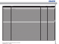
ASCII
Function
Operations supported
Legal modifiers
OSDW 1
OSD Warning On
Get, Set
A, ?
OSDW 0
OSD Warning Off
Get, Set
A, ?
POWR 1
Power On
Get, Set
A, ?
POWR 0
Power Off
Get, Set
A, ?
VRGB 0
RGB Video OFF
Get, Set
A, ?
VRGB 1
RGB Video Component
Get, Set
A, ?
SCBO 0
Secondary Color Boost off
Get, Set
A, ?
SCBO 1
Secondary Color Boost on
Get, Set
A, ?
SCAN 1
Source scan On
Get, Set
A, ?
SCAN 0
Source scan Off
Get, Set
A, ?
IVGA
Select VGA
Get, Set
A, ?
IBNC
Select BNC
Get, Set
A, ?
IDVI
Select DVI
Get, Set
A, ?
ISVI
Select S-video
Get, Set
A, ?
ICVI
Select Composite video
Get, Set
A, ?
IYPP
Select Component YPbPr
Get, Set
A, ?
IABS [0...6] See section 10
Set source abs value
Get, Set
A, R, ?, ?M, ?N
TEST 1
Test Image On
Get, Set
A, ?
TEST 0
Test Image Off
Get, Set
A, ?
LPW1
Lamp 1 Power
Get, Set
A, ?,
LTR1
Lamp 1 runtime
Get
A, ?
LHO1
Lamp 1 Total Light On Time Hours Get
Get
A, ?
LST1
Lamp 1 Status Get
Get
A, ?
LRM1
Lamp 1 Estimated Remaining Lamp Time
Get
A, ?
LPW2
Lamp 2 Power
Get, Set
A, ?,
LAMP CONTROL:
DS+65, DS+650 RS232 and LAN Technical Reference Information
020-000056-02 Rev. 1 (08-2009)
13
ASCII
Function
Operations supported
Legal modifiers
LTR2
Lamp 2 runtime
Get
A, ?
LHO2
Lamp 2 Total Light On Time Hours Get
Get
A, ?
LST2
Lamp 2 Status Get
Get
A, ?
LRM2
Lamp 2 Estimated Remaining Lamp Time
Get
A, ?
ECOM 1
Eco Mode On
Get, Set
A, ?
ECOM 0
Eco Mode Off
Get, Set
A, ?
LACT 1
Lamp Set single 1
Get, Set
A, ?
LACT 2
Lamp Set Single 2
Get, Set
A, ?
SNGL
Lamp Mode Single
Get, Set
A, ?
DUAL
Lamp Mode Dual
Get, Set
A, ?
FOIN [1,2,3]
Focus in [slow, medium, fast)
Set
A
FOUT [1,2,3]
Focus out
Set
A
ZOIN [1,2,3]
Zoom in
Set
A
ZOUT [1,2,3]
Zoom out
Set
A
IROP [1,2,3]
Iris open
Set
A
IRCL [1,2,3]
Iris close
Set
A
LSDW [1,2,3]
Lens shift down
Set
A
LSUP [1,2,3]
Lens shift up
Set
A
LSLF [1,2,3]
Lens shift left
Set
A
LSRH [1,2,3]
Len shift right
Set
A
SHUT 0
Shutter open
Get, Set
A, ?
SHUT 1
Shutter close
Get, Set
A, ?
LENS (see section 6.10)
Lens type mounted
Get
A, ?
S1T1
Select Scaling 1:1
Get, Set
A, ?
S169
Select Scaling 16:9
Get, Set
A, ?
SANA
Select Scaling Anamorphic
Get, Set
A, ?
SFLA
Select Scaling FillAll
Get, Set
A, ?
SFAR
Select Scaling FillAspectRatio
Get, Set
A, ?
LENS CONTROL:
PICTURE SETTINGS:
14
DS+65, DS+650 RS232 and LAN Technical Reference Information
020-000056-02 Rev. 1 (08-2009)
ASCII
Function
Operations supported
Legal modifiers
SLET
Select Scaling Letterbox to 16:9
Get, Set
A, ?
SLST
Select Scaling Letterbox st to 16:9
Get, Set
A, ?
SZOM
Select Scaling Zoom
Get, Set
A, ?
SCIN
Select Scaling Cinemascope
Get, Set
A, ?
See section 10
Set scaling abs value
Get, Set
A, R, ?, ?M, ?N
BRIG
Brightness
Get, Set
A, R, ?, ?M, ?N
CNTR
Contrast
Get, Set
A, R, ?, ?M, ?N
CSAT
Saturation
Get, Set
A, R, ?, ?M, ?N
SABS [0..3, 9-10, 13-14]
Color calibrated unit:
CMCU
Select Color Management Custom
Get, Set
A, ?
Select Custom mode RGB
Get, Set
A, ?
CTRD
Red Color Temperature
Get, Set
A, R, ?, ?M, ?N
CTGR
Green Color Temperature
Get, Set
A, R, ?, ?M, ?N
CTBL
Blue Color Temperature
Get, Set
A, R, ?, ?M, ?N
Select Custom mode Coordinates
Get, Set
A, ?
X-coordinate
Get, Set
A, R, ?, ?M, ?N
CMYV
Y-coordinate
Get, Set
A, R, ?, ?M, ?N
RD65
Reset coordinates to D65
Execute
A
Select Color Management Temperature
Get, Set
A, ?
Color Temperature
Get, Set
A, R, ?, ?M, ?N
Select Color Management Native (not corrected)
Get, Set
A, ?
CT65
Select colortemp 6500
Get, Set
A, ?
CT73
Select colortemp 7300
Get, Set
A, ?
CT93
Select colortemp 9300
Get, Set
A, ?
CTCU
Select custom color temp
Get, Set
A, ?
CTRD
Red color temperature
Get, Set
A, R, ?, ?M, ?N
CTGR
Green color temperature
Get, Set
A, R, ?, ?M, ?N
CTBL
Blue color temperature
Get, Set
A, R, ?, ?M, ?N
CCRG
CCXY
CMXV
CMTE
CTMP [32..97]
CMNA
Not Color calibrated unit:
DS+65, DS+650 RS232 and LAN Technical Reference Information
020-000056-02 Rev. 1 (08-2009)
15
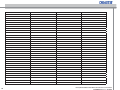
Source correction:
CRED
Red Gain
Get, Set
A, R, ?, ?M, ?N
BRED
Red Offset
Get, Set
A, R, ?, ?M, ?N
CGRE
Green Gain
Get, Set
A, R, ?, ?M, ?N
BGRE
Green Offset
Get, Set
A, R, ?, ?M, ?N
CBLU
Blue Gain
Get, Set
A, R, ?, ?M, ?N
BBLU
Blue Offset
Get, Set
A, R, ?, ?M, ?N
FREQ
Frequency
Get, Set
A, R, ?, ?M, ?N
GAFI 1
Select Gamma Film 1
Get, Set
A, ?
GAFI 2
Select Gamma Film 2
Get, Set
A, ?
GAVI 1
Select Gamma Video 1
Get, Set
A, ?
GAVI 2
Select Gamma Video 2
Get, Set
A, ?
GACO 1
Select Gamma Computer 1
Get, Set
A, ?
GACO 2
Select Gamma Computer 2
Get, Set
A, ?
WPEK [0-10]
WhitePeaking
Get, Set
A, R, ?, ?M, ?N
VHUE
Hue video
Get, Set
A, R, ?, ?M, ?N
VKEY
Vertical keystone
Get, Set
A, R, ?, ?M, ?N
HKEY
Horizontal keystone
Get, Set
A, R, ?, ?M, ?N
NROF
Noise reduction off
Get, Set
A, ?
NRAU
Noise reduction auto
Get, Set
A, ?
NRMA
Noise reduction manual
Get, Set
A, ?
Noise reduction lvl
Get
A, R, ?, ?M, ?N
PHSE
Phase
Get, Set
A, R, ?, ?M, ?N
VPOS
Vertical position
Get, Set
A, R, ?, ?M, ?N
HPOS
Horizontal position
Get, Set
A, R, ?, ?M, ?N
SZHZ
Resize Horizontally
Get, Set
A, R, ?, ?M, ?N
NRLV
16
DS+65, DS+650 RS232 and LAN Technical Reference Information
020-000056-02 Rev. 1 (08-2009)
SZVT
Resize Vertically
Get, Set
A, R, ?, ?M, ?N
SZEN 0
Resize OFF Get, Set
Get, Set
A, ?
SZEN 1
Resize ON Get, Set
Get, Set
A, ?
SHRP
Sharpness
Get, Set
A, R, ?, ?M, ?N
VAUT
Select Video Format Auto (default)
Get, Set
A, ?
VNTC
Select Video Format NTSC
Get, Set
A, ?
VPAL
Select Video Format PAL
Get, Set
A, ?
VSEC
Select Video Format SECAM
Get, Set
A, ?
VDVD
Select Video Type DVD
Get, Set
A, ?
VVCR
Select Video Type VCR
Get, Set
A, ?
FMMA
Fan main RPM
Get
A, ?
FMLM
Fan lamp 1 RPM
Get
A, ?
FMDM
Fan ballast 1 RPM
Get
A, ?
FMLS
Fan lamp 2 RPM
Get
A, ?
FMDS
Fan ballast 2 RPM
Get
A, ?
ECHO 0
Turn acknowledge off
Get, Set
A, ?
ECHO 1
Turn acknowledge on
Get, Set
A, ?
TPOU
Exhaust temperature
Get
A, ?
TPWA
Watchdog temperature
Get
A, ?
STATUS:
SWVR
Software Version Get
Get
A, ?
THRM (see section 6.10)
Thermal Monitor Get
Get
A, R, ?, ?M, ?N
RSAU
RS232 address mode auto
Get, Set
A, ?
RSFI
RS232 address mode fixed
Get, Set
A, ?
DS+65, DS+650 RS232 and LAN Technical Reference Information
020-000056-02 Rev. 1 (08-2009)
17
Mnenomic
IABS [0..2, 4..6]
SABS[0..3, 9-10, 13-14]
Table
Comments
Ignore other values returned, no source is connected.
0
0 – BNC
1
1 – VGA
2
2 – DVI
3
3 – YPbPr interlace
4
4 – S-Video
5
5 – Composite Video
6
6 – YPbPr progressive
0 – 1to1 (only VGA)
Use of other numbers may result in poor picture quality, and is
not recommended.
1 – fill all (only VGA)
2 – fill aspect ratio
3 – fill 16:9
9 – letterbox to 16:9
10 – letterbox subtitle to 16:9
13 – zoom (only Video)
14 – anamorphic
16 - cinemascope
ORIE[0..3]
0 – Desktop front
0 – Normal, everything OK
1 – Ceiling rear
2 – Desktop rear
3 – Ceiling front
THRM [0..2, 7..11]
1 – Temperature too high (shutdown)
2 – Temperature warning (close to shutdown)
7 – Fan lamp 1 stopped
8 – Fan lamp 2 stopped
9 – Fan ballast 1 stopped
10 – Fan ballast 2 stopped
11 – Fan main stopped
LENS [1..7]
1 – ultra wide
2 – wide
3 – super tele zoom
4 – tele zoom
5 – wide zoom
6 – standard
7 – no lens mounted
18
DS+65, DS+650 RS232 and LAN Technical Reference Information
020-000056-02 Rev. 1 (08-2009)
6.8
Examples
Responses/acknowledges are marked with green color. They can/will not be received if acknowledge is turned OFF (see section 6 ).
The protocol accepts one single SPACE between fields, or no SPACE between fields.
SET-commands:
POWER ON:
:
P
O
W
R
1
CR
:POWR 1#0x0D
ACKNOWLEDGE POWER ON:
%
0
0
1
P
O
W
R
0
0
0
0
0
1
CR
%001 POWR 000001CR
POWER OFF with address 100:
:
1
0
0
P
O
W
R
0
CR
:100 POWR 0#0x0D
ACKNOWLEDGE POWER OFF from address 100:
%
0
0
1
P
O
W
R
0
0
0
0
0
1
CR
%100 POWR 000000CR
DS+65, DS+650 RS232 and LAN Technical Reference Information
020-000056-02 Rev. 1 (08-2009)
19
SET current value BRIGHTNESS to value 60:
:
B
R
I
G
6
0
CR
:BRIG 60#0x0D
ACKNOWLEDGE BRIGHTNESS:
%
0
0
1
B
R
I
G
0
0
0
0
6
0
CR
%001 BRIG 000060CR
SET current value BRIGHTNESS to value 34 with address 45:
:
0
4
5
B
R
I
G
3
4
CR
:045 BRIG 34#0x0D
or
SET current value BRIGHTNESS to value 34 with address 45:
:
4
5
B
R
I
G
3
4
CR
:45 BRIG 34#0x0D
ACKNOWLEDGE BRIGHTNESS from address 45:
%
0
4
5
B
R
I
G
0
0
0
0
6
0
CR
%045 BRIG 000034CR
INCREMENT value CONTRAST:
:
C
N
T
R
R
1
CR
:CNTR R1#0x0D
ACKNOWLEDGE CONTRAST INCREMENT:
%
0
0
1
C
N
T
R
0
0
0
1
8
0
CR
%001 CNTR 000180CR
DECREMENT value CONTRAST:
:
C
N
T
R
R
-
1
CR
:CNTR R-1#0x0D
ACKNOWLEDGE CONTRAST DECREMENT:
%
0
0
1
C
N
T
R
0
0
0
1
7
9
CR
%001 CNTR 000179CR
20
DS+65, DS+650 RS232 and LAN Technical Reference Information
020-000056-02 Rev. 1 (08-2009)
INCREASE value CONTRAST BY 21:
:
C
N
T
R
R
2
1
CR
:CNTR R21#0x0D
ACKNOWLEDGE CONTRAST INCREASE:
%
0
0
1
C
N
T
R
0
0
0
2
0
0
CR
%001 CNTR 000200CR
DECREASE value CONTRAST BY 21:
:
C
N
T
R
R
-
2
1
CR
:CNTR R-21#0x0D
ACKNOWLEDGE CONTRAST DECREASE:
%
0
0
1
C
N
T
R
0
0
0
1
7
9
CR
%001 CNTR 000179CR
GET-commands:
GET current value BRIGHTNESS:
:
B
R
I
G
?
CR
:BRIG?#0x0D
ACKNOWLEDGE BRIGHTNESS GET:
%
0
0
1
B
R
I
G
0
0
0
0
5
0
CR
%001 BRIG 000050CR
GET current value BRIGHTNESS from address 123:
:
1
2
3
B
R
I
G
?
CR
:123 BRIG ?#0x0D
ACKNOWLEDGE BRIGHTNESS from address 123:
%
1
2
3
B
R
I
G
0
0
0
0
5
0
CR
%123 BRIG 000050CR
GET MIN value VERTICAL KEYSTONE:
:
V
K
E
Y
?
N
CR
:VKEY ?N#0x0D
ACKNOWLEDGE GET MIN value VERTICAL KEYSTONE:
%
0
0
1
V
K
E
Y
0
0
0
0
0
0
CR
%001 VKEY 000000CR
DS+65, DS+650 RS232 and LAN Technical Reference Information
020-000056-02 Rev. 1 (08-2009)
21
GET MAX value VERTICAL KEYSTONE:
:
V
K
E
Y
?
M
CR
:VKEY ?M#0x0D
ACKNOWLEDGE GET MAX value VERTICAL KEYSTONE:
%
0
0
1
V
K
E
Y
0
0
0
2
5
5
CR
%001 VKEY 000255CR
6.9
AMX/Crestron:
Command:
AMX:
Crestron:
Power ON
‘:POWR1’,$0d
:POWR1\r
Power OFF address 100
‘:’,$20’POWR’,$20,’0’,$0d
:\x20100\x20POWR\x200\r
or
or
‘:100POWR0’,$0d
:100POWR0\r
or
or
‘: 100 POWR 0’,$0d
: 100 POWR 0\r
SPACE characters should be used with hex notation or left out to avoid confusion/errors.
6.10
22
Truth-tables for abs-values
Mnenomic
Table
Comments
IABS [0..2, 4..6]
0 – VGA 1
1 – VGA 2
2 – DVI
3 – YPbPr interlace
4 – S-Video
5 – Composite Video
6 – YPbPr progressive
Ignore other values returned, no source is
connected.
SABS[0..3, 9-10, 13-14]
0 – 1to1 (only VGA)
1 – fill all (only VGA)
2 – fill aspect ratio
3 – fill 16:9
9 – letterbox to 16:9
10 – letterbox subtitle to 16:9
13 – zoom (only Video)
14 – anamorphic
Use of other numbers may result in poor
picture quality, and is not recommended.
ORIE[0..3]
0 – Desktop front
1 – Ceiling rear
2 – Desktop rear
3 – Ceiling front
DS+65, DS+650 RS232 and LAN Technical Reference Information
020-000056-02 Rev. 1 (08-2009)
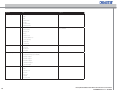
APPENDIX A, BINARY OPERATION PACKET TYPE
A.1
Operation Packet Type
The Operation packet is used by the host system to execute operations (such as Brightness, Contrast, Image Position, etc) in the target system. The Operation packet payload
size is 11 bytes.
A.2
Operation Packet Payload Format
Byte
Field Name
Field
Value
The source code definition of the Operation packet data structure is:
1-7
typedef struct
1-7
{
eOPERATION_TYPE eOpType;
WORD
WORD
DWORD
DWORD
LONG
LONG
LONG
} OPERATION_MESSAGE;
eOperation;
bIsAvail;
dwTarget;
dwValue;
lwMin;
lwMax;
lwInc;
// Operation type.
// Operation
// Operation validation.
// Operation target.
// Operation value.
// Lower limit.
// Upper limit.
// Increment.
This lets the user directly perform logical operations such as “Set Contrast = 80”.
If the user performs an OPERATION_GET, the returned packet will include operation
and target along with the value.
8
9-10
11
Operation Type
Description
Header, which consists of:
Byte 1-5: 0xBE 0xEF 0x03 0x19 0x00
Byte 6-7: CRC (not in use)
(see appendix C for an example of a
complete packet)
1
OPERATION_SET
2
OPERATION_GET
3
OPERATION_INCREMENT
4
OPERATION_DECREMENT
5
OPERATION_EXECUTE
7
OPERATION_DESCRIPTOR
Operation Number
Operation ID.
Operation Validation
Operation is valid, return only.
12
n/a (not available for use).
13-16
n/a (not available for use).
17-18
Operation Value
Value to SET or the value of the GET on
a return.
19-20
Operation Value
Not in use
21-24
Lower Limit
Lower Parameter limit.
25-28
Upper Limit
Upper Parameter limit
29-32
Increment
Increment steps within limits.
Table 2: Packet Payload format
DS+65, DS+650 RS232 and LAN Technical Reference Information
020-000056-02 Rev. 1 (08-2009)
23
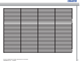
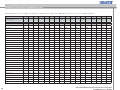
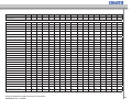
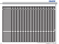
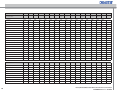
APPENDIX B, BINARY PACKETS IN HEXADECIMAL VALUES
Note! All operations in this section apply to the 32-bytes non-address protocol. Please refer to Appendix C for instructions on how to use address information.
Byte
1
2
3
4
5
6
7
Command Name:
8
9
10
operation
type
operation
-lo
operation
-hi
11,12
13
14-16
Target
17
18
oper
value lo
oper
value hi
19-32
Rev.:
SET:
24
Select BNC
0xBE
0xEF
0x03
0x19
0x00
0xEA
0xE9
0x01
0x01
0x44
0x00
0x00
0x00
0x00
0x00
0x00
Select VGA
0xBE
0xEF
0x03
0x19
0x00
0x7A
0x28
0x01
0x01
0x44
0x00
0x00
0x00
0x01
0x00
0x00
Select DVI
0xBE
0xEF
0x03
0x19
0x00
0x8B
0x68
0x01
0x01
0x44
0x00
0x00
0x00
0x02
0x00
0x00
Select S-video
0xBE
0xEF
0x03
0x19
0x00
0x29
0xEB
0x01
0x01
0x44
0x00
0x00
0x00
0x04
0x00
0x00
Select Composite video
0xBE
0xEF
0x03
0x19
0x00
0xB9
0x2A
0x01
0x01
0x44
0x00
0x00
0x00
0x05
0x00
0x00
Select Component YPbPr1
0xBE
0xEF
0x03
0x19
0x00
0x48
0x6A
0x01
0x01
0x44
0x00
0x00
0x00
0x06
0x00
0x00
Source scan On
0xBE
0xEF
0x03
0x19
0x00
0xEB
0xC9
0x01
0x23
0x44
0x00
0x00
0x00
0x00
0x00
0x00
Source scan Off
0xBE
0xEF
0x03
0x19
0x00
0x8A
0x48
0x01
0x23
0x44
0x00
0x00
0x00
0x02
0x00
0x00
Power On
0xBE
0xEF
0x03
0x19
0x00
0x12
0xD5
0x01
0x9C
0x02
0x00
0x00
0x00
0x01
0x00
0x00
Power Off
0xBE
0xEF
0x03
0x19
0x00
0x82
0x14
0x01
0x9C
0x02
0x00
0x00
0x00
0x00
0x00
0x00
Select Scaling 1:1
0xBE
0xEF
0x03
0x19
0x00
0x55
0xB2
0x01
0x16
0x44
0x00
0x00
0x00
0x00
0x00
0x00
Select Scaling 16:9
0xBE
0xEF
0x03
0x19
0x00
0xA4
0xF2
0x01
0x16
0x44
0x00
0x00
0x00
0x03
0x00
0x00
Select Scaling Anamorphic
0xBE
0xEF
0x03
0x19
0x00
0x31
0x36
0x01
0x16
0x44
0x00
0x00
0x00
0x0E
0x00
0x00
Select Scaling FillAll
0xBE
0xEF
0x03
0x19
0x00
0xC5
0x73
0x01
0x16
0x44
0x00
0x00
0x00
0x01
0x00
0x00
Select Scaling FillAspectRatio
0xBE
0xEF
0x03
0x19
0x00
0x34
0x33
0x01
0x16
0x44
0x00
0x00
0x00
0x02
0x00
0x00
Select Scaling Letterbox to 16:9
0xBE
0xEF
0x03
0x19
0x00
0x03
0x74
0x01
0x16
0x44
0x00
0x00
0x00
0x09
0x00
0x00
Select Scaling Letterbox st to 16:9
0xBE
0xEF
0x03
0x19
0x00
0xF2
0x34
0x01
0x16
0x44
0x00
0x00
0x00
0x0A
0x00
0x00
Select Scaling Cinemascope
0xBE
0xEF
0x03
0x19
0x00
0x99
0xBF
0x01
0x16
0x44
0x00
0x00
0x00
0x10
0x00
0x00
Gamma Film 1
0xBE
0xEF
0x03
0x19
0x00
0x63
0x55
0x01
0x68
0x06
0x00
0x00
0x00
0x00
0x00
0x00
Gamma Film 2
0xBE
0xEF
0x03
0x19
0x00
0xF3
0x94
0x01
0x68
0x06
0x00
0x00
0x00
0x01
0x00
0x00
Gamma Video 1
0xBE
0xEF
0x03
0x19
0x00
0x02
0xD4
0x01
0x68
0x06
0x00
0x00
0x00
0x02
0x00
0x00
Gamma Video 2
0xBE
0xEF
0x03
0x19
0x00
0x92
0x15
0x01
0x68
0x06
0x00
0x00
0x00
0x03
0x00
0x00
Gamma Computer 1
0xBE
0xEF
0x03
0x19
0x00
0x51
0x17
0x01
0x68
0x06
0x00
0x00
0x00
0x07
0x00
0x00
Gamma Computer 2
0xBE
0xEF
0x03
0x19
0x00
0xA5
0x52
0x01
0x68
0x06
0x00
0x00
0x00
0x08
0x00
0x00
DS+65, DS+650 RS232 and LAN Technical Reference Information
020-000056-02 Rev. 1 (08-2009)
Byte
1
2
3
4
5
6
7
Command Name:
8
9
10
operation
type
operation
-lo
operation
-hi
11,12
13
14-16
Target
17
18
oper
value lo
oper
value hi
19-32
Select Orientation Desktop Front
0xBE
0xEF
0x03
0x19
0x00
0x11
0x89
0x01
0x51
0x02
0x00
0x00
0x00
0x00
0x00
0x00
Select Orientation Ceiling Front
0xBE
0xEF
0x03
0x19
0x00
0xE0
0xC9
0x01
0x51
0x02
0x00
0x00
0x00
0x03
0x00
0x00
Select Orientation Desktop Rear
0xBE
0xEF
0x03
0x19
0x00
0x70
0x08
0x01
0x51
0x02
0x00
0x00
0x00
0x02
0x00
0x00
Select Orientation Rear Ceiling
0xBE
0xEF
0x03
0x19
0x00
0x81
0x48
0x01
0x51
0x02
0x00
0x00
0x00
0x01
0x00
0x00
Select Splash/Background Logo/
Black
0xBE
0xEF
0x03
0x19
0x00
0xFC
0x1E
0x01
0xA6
0x02
0x00
0x00
0x00
0x00
0x00
0x00
Select Splash/Background Logo
0xBE
0xEF
0x03
0x19
0x00
0x6C
0xDF
0x01
0xA6
0x02
0x00
0x00
0x00
0x01
0x00
0x00
Select Splash/Background Blue
0xBE
0xEF
0x03
0x19
0x00
0x9D
0x9F
0x01
0xA6
0x02
0x00
0x00
0x00
0x02
0x00
0x00
Select Splash/Background White
0xBE
0xEF
0x03
0x19
0x00
0x0D
0x5E
0x01
0xA6
0x02
0x00
0x00
0x00
0x03
0x00
0x00
Select Splash/Background Black
0xBE
0xEF
0x03
0x19
0x00
0x3F
0x1C
0x01
0xA6
0x02
0x00
0x00
0x00
0x04
0x00
0x00
OSD On
0xBE
0xEF
0x03
0x19
0x00
0x87
0x88
0x01
0x9D
0x02
0x00
0x00
0x00
0x01
0x00
0x00
OSD Off
0xBE
0xEF
0x03
0x19
0x00
0x17
0x49
0x01
0x9D
0x02
0x00
0x00
0x00
0x00
0x00
0x00
OSD Warning On
0xBE
0xEF
0x03
0x19
0x00
0x45
0x29
0x01
0xC7
0x02
0x00
0x00
0x00
0x01
0x00
0x00
OSD Warning Off
0xBE
0xEF
0x03
0x19
0x00
0xD5
0xE8
0x01
0xC7
0x02
0x00
0x00
0x00
0x00
0x00
0x00
Freeze Frame On
0xBE
0xEF
0x03
0x19
0x00
0xFA
0x76
0x01
0x0B
0x44
0x00
0x00
0x00
0x01
0x00
0x00
Freeze Frame Off
0xBE
0xEF
0x03
0x19
0x00
0x6A
0xB7
0x01
0x0B
0x44
0x00
0x00
0x00
0x00
0x00
0x00
Select Video Format Auto (default)
0xBE
0xEF
0x03
0x19
0x00
0xD9
0x90
0x01
0x13
0x44
0x00
0x00
0x00
0x10
0x00
0x00
Select Video Format NTSC
0xBE
0xEF
0x03
0x19
0x00
0x85
0x5C
0x01
0x13
0x44
0x00
0x00
0x00
0x01
0x00
0x00
Select Video Format PAL
0xBE
0xEF
0x03
0x19
0x00
0xB7
0x1E
0x01
0x13
0x44
0x00
0x00
0x00
0x06
0x00
0x00
Select Video Format SECAM
0xBE
0xEF
0x03
0x19
0x00
0xD3
0x9A
0x01
0x13
0x44
0x00
0x00
0x00
0x08
0x00
0x00
Select Video Type DVD
0xBE
0xEF
0x03
0x19
0x00
0x00
0x0E
0x01
0x09
0x44
0x00
0x00
0x00
0x00
0x00
0x00
Select Video Type VCR
0xBE
0xEF
0x03
0x19
0x00
0x90
0xCF
0x01
0x09
0x44
0x00
0x00
0x00
0x01
0x00
0x00
RGB Video OFF
0xBE
0xEF
0x03
0x19
0x00
0x55
0xB6
0x01
0xCD
0x02
0x00
0x00
0x00
0x00
0x00
0x00
RGB Video Component
0xBE
0xEF
0x03
0x19
0x00
0x34
0x37
0x01
0xCD
0x02
0x00
0x00
0x00
0x02
0x00
0x00
Test Image On
0xBE
0xEF
0x03
0x19
0x00
0xE3
0x44
0x01
0x1D
0x04
0x00
0x00
0x00
0x01
0x00
0x00
Test Image Off
0xBE
0xEF
0x03
0x19
0x00
0x73
0x85
0x01
0x1D
0x04
0x00
0x00
0x00
0x00
0x00
0x00
Eco Mode On
0xBE
0xEF
0x03
0x19
0x00
0x45
0xB9
0x01
0xD6
0x02
0x00
0x00
0x00
0x01
0x00
0x00
Eco Mode Off
0xBE
0xEF
0x03
0x19
0x00
0xD5
0x78
0x01
0xD6
0x02
0x00
0x00
0x00
0x00
0x00
0x00
Select CCA mode RGB
0xBE
0xEF
0x03
0x19
0x00
0x98
0x0D
0x01
0x48
0x06
0x00
0x00
0x00
0x01
0x00
0x00
Select CCA mode Coordinates
0xBE
0xEF
0x03
0x19
0x00
0x08
0xCC
0x01
0x48
0x06
0x00
0x00
0x00
0x00
0x00
0x00
DS+65, DS+650 RS232 and LAN Technical Reference Information
020-000056-02 Rev. 1 (08-2009)
Rev.:
25
Byte
1
2
3
4
5
6
7
Command Name:
Resize On
8
9
10
operation
type
operation
-lo
operation
-hi
0x04
11,12
13
14-16
Target
0x00
0x00
0x00
17
18
oper
value lo
oper
value hi
0x01
0x00
19-32
0xBE
0xEF
0x03
0x19
0x00
0x67
0x0A
0x01
0x8E
Resize Off
0xBE
0xEF
0x03
0x19
0x00
0xF7
0xCB
0x01
0x8E
0x04
0x00
0x00
0x00
0x00
0x00
0x00
Secondary Color Boost ON
0xBE
0xEF
0x03
0x19
0x00
0xF9
0x12
0x01
0xB6
0x02
0x00
0x00
0x00
0x01
0x00
0x00
Secondary Color Boost OFF
0xBE
0xEF
0x03
0x19
0x00
0x69
0xD3
0x01
0xB6
0x02
0x00
0x00
0x00
0x00
0x00
0x00
Projector Control Mode RiMi
0xBE
0xEF
0x03
0x19
0x00
0x21
0xA4
0x01
0xD7
0x02
0x00
0x00
0x00
0x02
0x00
0x00
Projector Control Mode External
0xBE
0xEF
0x03
0x19
0x00
0x40
0x25
0x01
0xD7
0x02
0x00
0x00
0x00
0x00
0x00
0x00
RS232 Address Mode Auto
0xBE
0xEF
0x03
0x19
0x00
0xA2
0x4E
0x01
0x57
0x03
0x00
0x00
0x00
0x01
0x00
0x00
RS232 Address Mode Fixed
0xBE
0xEF
0x03
0x19
0x00
0x32
0x8F
0x01
0x57
0x03
0x00
0x00
0x00
0x00
0x00
0x00
Brightness Increment
0xBE
0xEF
0x03
0x19
0x00
0xC1
0xC9
0x03
0x03
0x40
0x00
0x00
0x00
0x00
0x00
0x00
Brightness Decrement
0xBE
0xEF
0x03
0x19
0x00
0xAF
0x63
0x04
0x03
0x40
0x00
0x00
0x00
0x00
0x00
0x00
Contrast Increment
0xBE
0xEF
0x03
0x19
0x00
0xEB
0x5F
0x03
0x04
0x40
0x00
0x00
0x00
0x00
0x00
0x00
Contrast Decrement
0xBE
0xEF
0x03
0x19
0x00
0x85
0xF5
0x04
0x04
0x40
0x00
0x00
0x00
0x00
0x00
0x00
Vertical Keystone Increment
0xBE
0xEF
0x03
0x19
0x00
0x94
0x75
0x03
0x1C
0x40
0x00
0x00
0x00
0x00
0x00
0x00
Vertical Keystone Decrement
0xBE
0xEF
0x03
0x19
0x00
0xFA
0xDF
0x04
0x1C
0x40
0x00
0x00
0x00
0x00
0x00
0x00
Horizontal Keystone Increment
0xBE
0xEF
0x03
0x19
0x00
0x8A
0x44
0x03
0x21
0x02
0x00
0x00
0x00
0x00
0x00
0x00
Horizontal Keystone Decrement
0xBE
0xEF
0x03
0x19
0x00
0xE4
0xEE
0x04
0x21
0x02
0x00
0x00
0x00
0x00
0x00
0x00
Color Saturation Increment
0xBE
0xEF
0x03
0x19
0x00
0x01
0xB8
0x03
0x0C
0x40
0x00
0x00
0x00
0x00
0x00
0x00
Color Saturation Decrement
0xBE
0xEF
0x03
0x19
0x00
0x6F
0x12
0x04
0x0C
0x40
0x00
0x00
0x00
0x00
0x00
0x00
Horizontal Position Increment
0xBE
0xEF
0x03
0x19
0x00
0x6B
0x01
0x03
0x0E
0x40
0x00
0x00
0x00
0x00
0x00
0x00
Horizontal Position Decrement
0xBE
0xEF
0x03
0x19
0x00
0x05
0xAB
0x04
0x0E
0x40
0x00
0x00
0x00
0x00
0x00
0x00
Vertical Position Increment
0xBE
0xEF
0x03
0x19
0x00
0xFE
0x5C
0x03
0x0F
0x40
0x00
0x00
0x00
0x00
0x00
0x00
Vertical Position Decrement
0xBE
0xEF
0x03
0x19
0x00
0x90
0xF6
0x04
0x0F
0x40
0x00
0x00
0x00
0x00
0x00
0x00
Hue Increment
0xBE
0xEF
0x03
0x19
0x00
0x2B
0x2E
0x03
0x0B
0x40
0x00
0x00
0x00
0x00
0x00
0x00
Hue Decrement
0xBE
0xEF
0x03
0x19
0x00
0x45
0x84
0x04
0x0B
0x40
0x00
0x00
0x00
0x00
0x00
0x00
Sharpness Increment
0xBE
0xEF
0x03
0x19
0x00
0x94
0xE5
0x03
0x0D
0x40
0x00
0x00
0x00
0x00
0x00
0x00
Sharpness Decrement
0xBE
0xEF
0x03
0x19
0x00
0xFA
0x4F
0x04
0x0D
0x40
0x00
0x00
0x00
0x00
0x00
0x00
Phase Increment
0xBE
0xEF
0x03
0x19
0x00
0xAB
0xE0
0x03
0x10
0x40
0x00
0x00
0x00
0x00
0x00
0x00
Phase Decrement
0xBE
0xEF
0x03
0x19
0x00
0xC5
0x4A
0x04
0x10
0x40
0x00
0x00
0x00
0x00
0x00
0x00
Frequency Increment
0xBE
0xEF
0x03
0x19
0x00
0x7E
0x92
0x03
0x14
0x40
0x00
0x00
0x00
0x00
0x00
0x00
Frequency Decrement
0xBE
0xEF
0x03
0x19
0x00
0x10
0x38
0x04
0x14
0x40
0x00
0x00
0x00
0x00
0x00
0x00
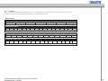
Rev.:
0x00
INCREMENT/DECREMENT:
26
DS+65, DS+650 RS232 and LAN Technical Reference Information
020-000056-02 Rev. 1 (08-2009)
Byte
1
2
3
4
5
6
7
Command Name:
0x27
8
9
10
operation
type
operation
-lo
operation
-hi
0x03
0x5C
0x03
11,12
13
14-16
Target
0x00
0x00
0x00
17
18
oper
value lo
oper
value hi
0x00
0x00
19-32
Lamp power 1 increment
0xBE
0xEF
0x03
0x19
0x00
0x95
Lamp power 1 decrement
0xBE
0xEF
0x03
0x19
0x00
0xFB
0x8D
0x04
0x5C
0x03
0x00
0x00
0x00
0x00
0x00
0x00
Lamp power 2 increment
0xBE
0xEF
0x03
0x19
0x00
0XB4
0xFE
0XB8
0x0B
0x03
0x00
0x00
0x00
0x00
0x00
0x00
Lamp power 2 decrement
0xBE
0xEF
0x03
0x19
0x00
0xDA
0x54
0XB8
0x0B
0x03
0x00
0x00
0x00
0x00
0x00
0x00
Red Brightness Increment
0xBE
0xEF
0x03
0x19
0x00
0x7E
0x02
0x03
0x05
0x40
0x00
0x00
0x00
0x00
0x00
0x00
Red Brightness Decrement
0xBE
0xEF
0x03
0x19
0x00
0x10
0xA8
0x04
0x05
0x40
0x00
0x00
0x00
0x00
0x00
0x00
Red Contrast Increment
0xBE
0xEF
0x03
0x19
0x00
0x81
0xE6
0x03
0x06
0x40
0x00
0x00
0x00
0x00
0x00
0x00
Red Contrast Decrement
0xBE
0xEF
0x03
0x19
0x00
0xEF
0x4C
0x04
0x06
0x40
0x00
0x00
0x00
0x00
0x00
0x00
Resize Vertical Increment
0xBE
0xEF
0x03
0x19
0x00
0x2E
0x1A
0x03
0x6B
0x06
0x00
0x00
0x00
0x00
0x00
0x00
Resize Vertical Decrement
0xBE
0xEF
0x03
0x19
0x00
0x40
0xB0
0x04
0x6B
0x06
0x00
0x00
0x00
0x00
0x00
0x00
Resize Horizontal Increment
0xBE
0xEF
0x03
0x19
0x00
0xBB
0x47
0x03
0x6A
0x06
0x00
0x00
0x00
0x00
0x00
0x00
Resize Horizontal Decrement
0xBE
0xEF
0x03
0x19
0x00
0xD5
0xED
0x04
0x6A
0x06
0x00
0x00
0x00
0x00
0x00
0x00
Green Brightness Increment
0xBE
0xEF
0x03
0x19
0x00
0x14
0xBB
0x03
0x07
0x40
0x00
0x00
0x00
0x00
0x00
0x00
Green Brightness Decrement
0xBE
0xEF
0x03
0x19
0x00
0x7A
0x11
0x04
0x07
0x40
0x00
0x00
0x00
0x00
0x00
0x00
Green Contrast Increment
0xBE
0xEF
0x03
0x19
0x00
0xD4
0xCA
0x03
0x08
0x40
0x00
0x00
0x00
0x00
0x00
0x00
Green Contrast Decrement
0xBE
0xEF
0x03
0x19
0x00
0xBA
0x60
0x04
0x08
0x40
0x00
0x00
0x00
0x00
0x00
0x00
Blue Brightness Increment
0xBE
0xEF
0x03
0x19
0x00
0x41
0x97
0x03
0x09
0x40
0x00
0x00
0x00
0x00
0x00
0x00
Blue Brightness Decrement
0xBE
0xEF
0x03
0x19
0x00
0x2F
0x3D
0x04
0x09
0x40
0x00
0x00
0x00
0x00
0x00
0x00
Blue Contrast Increment
0xBE
0xEF
0x03
0x19
0x00
0xBE
0x73
0x03
0x0A
0x40
0x00
0x00
0x00
0x00
0x00
0x00
Blue Contrast Decrement
0xBE
0xEF
0x03
0x19
0x00
0xD0
0xD9
0x04
0x0A
0x40
0x00
0x00
0x00
0x00
0x00
0x00
XCoordinates Increment
0xBE
0xEF
0x03
0x19
0x00
0x0F
0x2F
0x03
0xFD
0x05
0x00
0x00
0x00
0x00
0x00
0x00
XCoordinates Decrement
0xBE
0xEF
0x03
0x19
0x00
0x61
0x85
0x04
0xFD
0x05
0x00
0x00
0x00
0x00
0x00
0x00
YCoordinates Increment
0xBE
0xEF
0x03
0x19
0x00
0xF0
0xCB
0x03
0xFE
0x05
0x00
0x00
0x00
0x00
0x00
0x00
YCoordinates Decrement
0xBE
0xEF
0x03
0x19
0x00
0x9E
0x61
0x04
0xFE
0x05
0x00
0x00
0x00
0x00
0x00
0x00
White Boost Increment
0xBE
0xEF
0x03
0x19
0x00
0x44
0xA3
0x03
0xFE
0x06
0x00
0x00
0x00
0x00
0x00
0x00
White Boost Decrement
0xBE
0xEF
0x03
0x19
0x00
0x2A
0x09
0x04
0xFE
0x06
0x00
0x00
0x00
0x00
0x00
0x00
Lamp Ignition Get
0xBE
0xEF
0x03
0x19
0x00
0x62
0x93
0x02
0xA2
0x02
0x00
0x00
0x00
0x00
0x00
0x00
Thermal Monitor Get
0xBE
0xEF
0x03
0x19
0x00
0xDC
0xE8
0x02
0x97
0x02
0x00
0x00
0x00
0x00
0x00
0x00
Source Get
0xBE
0xEF
0x03
0x19
0x00
0xA1
0x16
0x02
0x01
0x44
0x00
0x00
0x00
0x00
0x00
0x00
Orientation Get
0xBE
0xEF
0x03
0x19
0x00
0x5A
0x76
0x02
0x51
0x02
0x00
0x00
0x00
0x00
0x00
0x00
Rev.:
0x00
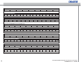
GET:
DS+65, DS+650 RS232 and LAN Technical Reference Information
020-000056-02 Rev. 1 (08-2009)
27
Byte
1
2
3
4
5
6
7
Command Name:
8
9
10
operation
type
operation
-lo
operation
-hi
11,12
13
14-16
0x02
0x9C
0x02
0x00
0x00
0x00
0x00
0x00
0x00
Target
17
18
oper
value lo
oper
value hi
19-32
Power Get
0xBE
0xEF
0x03
0x19
0x00
0xC9
0xEB
Brightness Get
0xBE
0xEF
0x03
0x19
0x00
0x38
0x9D
0x02
0x03
0x40
0x00
0x00
0x00
0x00
0x00
0x00
Contrast Get
0xBE
0xEF
0x03
0x19
0x00
0x12
0x0B
0x02
0x04
0x40
0x00
0x00
0x00
0x00
0x00
0x00
Color Saturation Get
0xBE
0xEF
0x03
0x19
0x00
0xF8
0xEC
0x02
0x0C
0x40
0x00
0x00
0x00
0x00
0x00
0x00
Light On Time Hours 1 Get
0xBE
0xEF
0x03
0x19
0x00
0x2D
0xF2
0x02
0x04
0x10
0x00
0x00
0x00
0x00
0x00
0x00
Light On Time Hours 2 Get
0xBE
0xEF
0x03
0x19
0x00
0x6C
0x76
0x02
0x31
0x04
0x00
0x00
0x00
0x00
0x00
0x00
Unit On Time Hours Get
0xBE
0xEF
0x03
0x19
0x00
0x92
0x39
0x02
0x02
0x10
0x00
0x00
0x00
0x00
0x00
0x00
Lamp On
0xBE
0xEF
0x03
0x19
0x00
0x07
0x7F
0x02
0x00
0x04
0x00
0x00
0x00
0x00
0x00
0x00
Software Version Get
0xBE
0xEF
0x03
0x19
0x00
0x08
0x2A
0x02
0xA0
0x02
0x00
0x00
0x00
0x00
0x00
0x00
Estimated Remaining Lamp 1Time
0xBE
0xEF
0x03
0x19
0x00
0x9F
0xA7
0x02
0xF4
0x02
0x00
0x00
0x00
0x00
0x00
0x00
Estimated Remaining Lamp 2Time
0xBE
0xEF
0x03
0x19
0x00
0x0A
0xFA
0x02
0xF5
0x02
0x00
0x00
0x00
0x00
0x00
0x00
Lamp Power 1 Get
0xBE
0xEF
0x03
0x19
0x00
0x6C
0x73
0x02
0x5C
0x03
0x00
0x00
0x00
0x00
0x00
0x00
Lamp Power 2 Get
0xBE
0xEF
0x03
0x19
0x00
0x4D
0xAA
0x02
0xB8
0x0B
0x00
0x00
0x00
0x00
0x00
0x00
Auto Adjust
0xBE
0xEF
0x03
0x19
0x00
0x2F
0xAE
0x05
0x03
0x42
0x00
0x00
0x00
0x00
0x00
0x00
Set CCA Coords to D65
0xBE
0xEF
0x03
0x19
0x00
0x07
0x9F
0x05
0x5E
0x06
0x00
0x00
0x00
0x00
0x00
0x00
Resize Reset
0xBE
0xEF
0x03
0x19
0x00
0x87
0x22
0x05
0x91
0x04
0x00
0x00
0x00
0x00
0x00
0x00
Factory Reset
0xBE
0xEF
0x03
0x19
0x00
0x6F
0xB9
0x05
0x01
0x22
0x00
0x00
0x00
0x00
0x00
0x00
Range Brightness
0xBE
0xEF
0x03
0x19
0x00
0xE4
0x9C
0x07
0x03
0x40
0x00
0x00
0x00
0x00
0x00
0x00
Range Contrast
0xBE
0xEF
0x03
0x19
0x00
0xCE
0x0A
0x07
0x04
0x40
0x00
0x00
0x00
0x00
0x00
0x00
Range Color/Saturation
0xBE
0xEF
0x03
0x19
0x00
0x24
0xED
0x07
0x0C
0x40
0x00
0x00
0x00
0x00
0x00
0x00
Range Red Brightness
0xBE
0xEF
0x03
0x19
0x00
0x5B
0x57
0x07
0x05
0x40
0x00
0x00
0x00
0x00
0x00
0x00
Range Red Contrast
0xBE
0xEF
0x03
0x19
0x00
0xA4
0xB3
0x07
0x06
0x40
0x00
0x00
0x00
0x00
0x00
0x00
Range Green Brightness
0xBE
0xEF
0x03
0x19
0x00
0x31
0xEE
0x07
0x07
0x40
0x00
0x00
0x00
0x00
0x00
0x00
Range Green Contrast
0xBE
0xEF
0x03
0x19
0x00
0xF1
0x9F
0x07
0x08
0x40
0x00
0x00
0x00
0x00
0x00
0x00
Range Blue Brightness
0xBE
0xEF
0x03
0x19
0x00
0x64
0xC2
0x07
0x09
0x40
0x00
0x00
0x00
0x00
0x00
0x00
Range Blue Contrast
0xBE
0xEF
0x03
0x19
0x00
0x9B
0x26
0x07
0x0A
0x40
0x00
0x00
0x00
0x00
0x00
0x00
Rev.:
EXECUTE:
DESCRIPTOR:
28
DS+65, DS+650 RS232 and LAN Technical Reference Information
020-000056-02 Rev. 1 (08-2009)
APPENDIX C, RS232 DAISY-CHAINING
C.1
About the protocol
The projectors can be daisy-chained and controlled independently by adding address
information to the original 32 byte binary RS232 message.
Table 5 shows the 34 bytes acknowledge message with address information. As for the
non-address message, the acknowledge message consist of a PAK (0x1E) followed by
the initial message sent from the host.
1
4
5
6
7
8
9
10-34
PAK
address magic
number
2
3
address
type of
msg
payload lo
payload hi
CRC lo
CRC hi
payload
0x1E
0xBA
0x000xFF
0xDA
Table 5: 34-bytes acknowledge address message
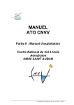
Figure 1: RS232 Daisy-Chaining
C.2
Address modes
Two different addressing mechanisms are available, auto and fixed. The default mode is
auto-addressing. It is important that all projectors in the chain are set to the same address mode. The address mode must be set from the projector’s menu system.
Figure 1 shows how to daisy-chain several projectors. The control system is connected
to RS232 IN (female) in projector 1. The projector 1 RS232 OUT (male) is connected to
projector 2 IN, and so on. Max numbers of projectors in a chain are 255.
NOTE! The original 32-bytes non-address binary protocol does not support addressing,
and commands using this protocol will only be executed by the first projector in the chain.
To independently address and control each projector in the chain, the original 32-bytes
protocol is extended with address information. The header size is increased from 7 to 8
bytes and the total packet is increased from 32 to 33 bytes. The acknowledge packet size
is increased from 33 to 34 bytes.
Table 3 shows the original non-address 32-bytes message.
1
2
magic number
0xBE
3
4
5
6
7
8-32
packet
type
payload
size lo
payload
size hi
CRC lo
CRC hi
payload
0xEF
C.2.1
Auto address mode
In auto address mode, the address of the projector is based on its physical position in the
chain. The first projector has address 1, the second has address 2 and so on.
C.2.2
Fixed address mode
In fixed mode, each projector needs to be programmed with a unique fixed address irrespective of its position in the chain. The address must be specified for each projector by
setting it from the projector’s menu system. If two or more projectors are equipped with
the same address, then only one of the projectors will respond to a message addressed
to that actual address.
Legal projector address range is 1 to 255 (0x01 – 0xFF).
Table 3: 32-bytes non-address message
1
2
address magic
number
0xBA
0xDA
3
address
4
packet
type
5
6
7
8
9-33
payload
size lo
payload
size hi
CRC lo
CRC hi
payload
0x000xFF
Table 4: 33-bytes address message
Legal message address range is 0-255, where 0 is broadcast address.
DS+65, DS+650 RS232 and LAN Technical Reference Information
020-000056-02 Rev. 1 (08-2009)
C.2.3
Broadcast
Address 0 (zero) is broadcast address. A broadcast message is sent to all projectors
in the chain regardless of the address mode. When a projector receives a broadcast
message it will execute the command and send the message to the next projector in the
chain. No acknowledge message will be sent in reply to a broadcast message.
C.3
Baud rate
The baud rate is configurable between 4800, 9600 and 19200. Default baud rate is
19200. If there are several projectors in the chain (>10) or high RS232 traffic it is strongly
recommended that the baud rate is reduced to 4800. This will reduce the processing load
at the first projectors in the chain.
29
C.4
Special short messages
If there are several projectors in the chain (>10) or high RS232 traffic, it is strongly recommended that an alternative shorter message is used. This will reduce the processing load
at the first projectors in the chain.
In a short message byte number 20 (19 for non-address) to 33 (32 for non-address) is
omitted. The message header must be updated with correct payload size, i.e byte 5 and
byte 6 (4 and 5 for non-address). If only 19 (18 for non-address) bytes is in use then the
payload size is set to 11 (0x0B). See example in section 2.5.
Note that a DESCRIPTOR message should not be sent with a short message, because
that type of message use bytes 20 – 33 in the response. All other message types can be
used.
C.5
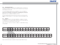
Examples
All available RS232 operations are described in Appendix C, and apply to the 32 bytes
non-address protocol. To use with the address information the two first bytes 0xBE 0xEF
must be replaced with the 0xBA 0xDA and an address byte.
Figure 2 shows the conversion from 32 bytes non-address to 33 bytes address message
for “select VGA1”.
32 bytes non-address message
Byte
Select vga1
1
2
3
4
5
6
7
8
9
10
11,12
13
14-16
17
18
19-32
0xBE
0xEF
0x03
0x19
0x00
0xEA
0xE9
0x01
0x044
0x00
0x00
0x00
0x00
0x00
0x00
0x00
33 bytes address message
Byte
Select vga1
1
2
3
4
5
6
7
8
9
10
11
12-13
14
15-17
18
19
20-33
0xBA
0xDA
0x05
0x03
0x19
0x00
0x00
0x00
0x01
0x00
0x44
0x00
0x00
0x00
0x00
0x00
0x00
[addr] = address 0x00 - 0xFF
Figure 2: Convert from 32-bytes non-address message to 33 bytes address message
30
DS+65, DS+650 RS232 and LAN Technical Reference Information
020-000056-02 Rev. 1 (08-2009)
Figure 3 shows a 33-bytes address message and the corresponding 19 bytes short message. Address in this example is 5 (0x05, byte 3). Payload_lo (byte 5) is set to 0x0B.
33 bytes address message
Byte
Select vga1
1
2
3
4
5
6
7
8
9
10
11
12-13
14
15-17
18
19
20-33
0xBA
0xDA
0x05
0x03
0x19
0x00
0x00
0x00
0x01
0x01
0x44
0x00
0x00
0x00
0x00
0x00
0x00
19 bytes address message
Byte
Select vga1
1
2
3
4
5
6
7
8
9
10
11
12-13
14
15-17
18
19
0xBA
0xDA
0x05
0x03
0x0B
0x00
0x00
0x00
0x01
0x01
0x44
0x00
0x00
0x00
0x00
0x00
Figure 3: Long (33 bytes) address message and corresponding short (19 bytes) address message.
Note that the CRC is not in use and can be left 0x00
DS+65, DS+650 RS232 and LAN Technical Reference Information
020-000056-02 Rev. 1 (08-2009)
31
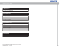
APPENDIX D, ADJUSTING CUSTOM COLOR TEMP USING RS232
Note: It is important to select ”custom color temp” before adjusting R/G/B temps, otherwise these commands will not work! All values are hexadecimal.
D.1 Choose “Custom color temp”
Select Color Temp Custom:
BE
EF
03
19
00
96
20
01
07
44
00
00
00
00
00
00
04
00
00
00
00
00
00
00
00
00
00
00
00
00
00
00
BE
EF
03
19
00
34
A3
01
07
44
00
00
00
00
00
00
02
00
00
00
00
00
00
00
00
00
00
00
00
00
00
00
Other choices are:
Select Color Temp 6500:
Select Color Temp 7300:
BE
EF
03
19
00
C5
E3
01
07
44
00
00
00
00
00
00
01
00
00
00
00
00
00
00
00
00
00
00
00
00
00
00
Select Color Temp 9300:
BE
EF
03
19
00
55
22
01
07
44
00
00
00
00
00
00
00
00
00
00
00
00
00
00
00
00
00
00
00
00
00
00
D.2 Adjust the color temperature by using the increment / decrement operations:
Red Temp Increment:
BE
EF
03
19
00
14
2B
03
16
40
00
00
00
00
00
00
00
00
00
00
00
00
00
00
00
00
00
00
00
00
00
00
Red Temp Decrement:
BE
EF
03
19
00
7A
81
04
16
40
00
00
00
00
00
00
00
00
00
00
00
00
00
00
00
00
00
00
00
00
00
00
Green Temp Increment:
BE
EF
03
19
00
81
76
03
17
40
00
00
00
00
00
00
00
00
00
00
00
00
00
00
00
00
00
00
00
00
00
00
Green Temp Decrement:
BE
EF
03
19
00
EF
DC
04
17
40
00
00
00
00
00
00
00
00
00
00
00
00
00
00
00
00
00
00
00
00
00
00
Blue Temp Increment:
BE
EF
03
19
00
41
07
03
18
40
00
00
00
00
00
00
00
00
00
00
00
00
00
00
00
00
00
00
00
00
00
00
Blue Temp Decrement:
BE
EF
03
19
00
2F
AD
04
18
40
00
00
00
00
00
00
00
00
00
00
00
00
00
00
00
00
00
00
00
00
00
00
You may now bring the adjusted custom setting forward by selecting “custom color temp”, either through keypad/remote or via RS232.
32
DS+65, DS+650 RS232 and LAN Technical Reference Information
020-000056-02 Rev. 1 (08-2009)
APPENDIX E, TRUTH TABLES
E.1 OSD Warning On:
When enabling OSD Warnings after beeing disabled, OSD is still disabled and must be
set to ON to become visible again.
E.2 Lamp Ignition states:
00 – Lamp does not ignite
01 – Lamp is warming up
02 – Lamp ignited
03 – Lamp is off
04 – Lamp is cooling down
E.3 Thermal Monitor states:
00 – OK
01 – Temperature too high
02 – Temperature warning
03 – Fan 70 x 70 stopped
04 – Fan 60 x 60 stopped
05 – Fan Blower stopped
E.4 Lamp On States
00 – Lamp is not lit
01 – Lamp is lit
DS+65, DS+650 RS232 and LAN Technical Reference Information
020-000056-02 Rev. 1 (08-2009)
33