1
AV-705, 706, 707/B LCD Keypad
INSTALLATION INSTRUCTIONS V3.04A
The AV-7075, AV-706 and AV-707 EasyKey™ are the future-generation keypads, with the
AV-707 New Look shape, fully-customized microprocessor remote station, multitasks
functions with 32 Keypad ID’s, comply with year 2000 requirements. The AV-706 is an
economic version LCD keypad, with same operations and electrical specifications as AV-707.
The AV-707, AV-707B and AV-706 are compatible with EasyLoader™ “PRO” suffix alarm
control panels: AV-2004/48DPRO, AV-2008/2016 Dublo. The DPRO and Dublo (Generation
III panels) types are an enhanced version of Series 2000 panels.
Before attempting to use the AV-705, AV-707 and AV-706, read thoroughly this manual and
the control panel manual (series 2000) large version installation manual.
Two rows, each of 16 characters display, provide full information and clear status of the
system. The keypad include simple and easy text editor for fast words writing.
Built-in standard-words and key-letters index for fast and easy custom programming in almost
any language.
Function keys, displayed upon request, facilitate setting and resetting, programmable constant
messages (e.g. time of day, service information, etc.), available in Latin or Hebrew characters.
Verify that your keypad/s version is same as panel version or higher
Ordering Information:
AV-707E: English text keypad. AV-707ETP: English text keypad with added Tamper.
AV-707B: English text keypad with three function buttons (fit panels Ver. 2.16 and later).
AV-706E: English text keypad. AV-706ETP: English text keypad with added Tamper.
AV-705: Remote keypad without LCD display (as AV-707) fits PRO & Dublo panels.
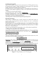
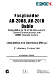
1. Wiring the AV-707, AV-706 and AV-705
AV-2004/48DPRO, AV-2008D Dublo supports up to four AV-707/706 keypads,
AV-2016 Dublo control panel supports up to eight keypads. AV-707B is compatible
with alarm panels starting version 2.16. When using four keypad or more add power
supply (like AV-21) to prevent loading the panel’s power supply.
To connect more keypads to the same system, add an external power supply (AV21). Wire length for each AV-707/706 Keypad should not exceed 200 meters, when
using 0.5 mm2 wires. In few keypads system, wire all keypads in parallel.
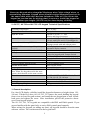
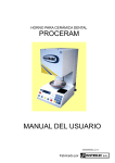
+12V -12V
Zone 8
OR YEL
YEL
PRO Control
Panel
+12V -12V
*TMP YEL OR
AV-706/7 keypad
* The TMP terminal is available with AV-707TP
Item: 4710
Figure 1: Keypad wiring
1
IMPORTANT!! Do not connect keypad to control panel with power on.
Never run Keypad wires alongside telephone wires, high voltage wires, or
transmitting antennae. Keypad wires should be wired separately and not in
the same cable with other devices (telephone, PIRs etc.) Do not use the
keypad as junction box for wiring power to sensors. Install the keypad at
human eyes height (150-180 cm) for clear display visibility
2. AV-707, AV-706 and AV-705 LCD keypad Technical Specifications
Operating Temperature
Maximum relative Humidity
Input DC Power
-10°C to 60°C
80% @ 20°C
Filtered 13.6V DC, +/− 10%
Polarity and Surge protection
Current Drain
50 mA with LEDs and LCD backlight Off
110 mA with LEDs and LCD backlight On
Dynamic Inner Memory EEPROM
Non-Volatile. Text stored at Control Panel
Messages stored with and without power
Display (LCD is shortening of Liquid Crystal LCD display 16 characters x 2 Rows
Display)
Automatic display contrast
Display Area (not available with AV-705)
60 X 16 mm
Wiring
4 wires connected to wires terminal
5 wires for keypads with Tamper Switch
Keys
12 Silicon Rubber Keys
Keys Protection
Manual tilt ABS door at AV-705, 707, 707B
Internal Buzzer
85 dB Piazo buzzer
Fixed Vocabulary Internal Words
Up to 30 common word
Internal Words Editor
Space, Delete, Insert
Language
Latin or Hebrew
Compatibility
Series 2000: PRO and Dublo types
Note: When few keypads used in the same
system, check that all are the same version
Dimensions
AV-705, AV-707, AV-707B: H=168, W=105
AV-706: H=105, W=140 mm
Housing
White ABS with Polypropylene Window
Packing
Color carton box, 30 per master box
Gross Shipping Weight
0.25kg
This product is subject to continuous enhancement and therefore specifications may be changed or altered without prior notice
3. General description
For clear LCD display visibility install the keypad at human eye height (about 150180 cm). Tilt the keys door, for AV-705, 707 remove the screw holding the keypad
front cover (at lower keypad section), and install the rear keypad part to wall. Attach
both parts and tighten the screw. After installation, pill-off the protective sheets
cover from keypad window.
The AV-705, 706, 707 keypads are compatible with PRO and Dublo panels. If you
are not familiar with the panel refer to series 2000 control panel manuals.
When wiring few keypads (or adding one later), all keypads should be from the same
software version. The version noted on the keypad back.
2
For cost saving application, as 2nd keypad use the AV-705. The AV-705 has the same
functions as AV-707, however, the LCD display is not included.
Upon power-up “Set Panel Time” is displayed, hold-down key ‘0’ then hold-down
key ‘1’, enter time in 24H format and #. To set date hold-down key ‘0’ then holddown key ‘2’, enter date in dd-mm-yy format and #. The '#' is mostly used as an
ENTER key, typed at the end of a command.
If the message: Download Texts is displayed when first powering-up the keypad,
wait until download texts from the panel to the keypad is finished.
To download texts enter Installer Programming mode (see chapter 5), type 200 then
71, downloading will start, wait for a while until Installer Progr is displayed on the
upper line. The downloading cannot be aborted.
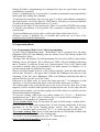
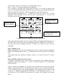
The second row displays the zone status. Each ‘’sign represents a zone. If a zone
is open, the zone’s number like 123567 will replace the .
If a zone had been bypassed, a '*' will appear instead. The control panel time is
displayed in the five rightmost positions.
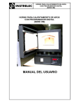
The first line displays system announcements, like: System Disarmed, Alarm, Low
Battery, etc. Refer to figure 2.
System Message
System
Disarmed
Figure 2: Zone status display 2008 Dublo
12:00
In Use mode, the LCD often shows the installer
LOGO (the logo is editable). To display zone
description Hold down key 3 twice.
Bypassed Zone
Close Zone
To save power, the LCD and keys backlight
Open Zone
Local Clock
turned OFF after 60 seconds upon ending the
entries (it turns ON again when an alarm
A V-7 0 7
occurs).
Most accessible functions of the LCD Keypad
are similar to those of the AV-701 (seven
segments keypad).
Refer to the Control Panel manual for Hold Down functions.
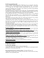
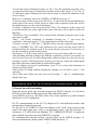
Hold down key 3 to display open zones, the result is zone numbers for the open
zones, and two dashes for close zone, as shown in figure 2A. The - - sign represents
a close zone. To display bypassed zone hold-down key 2, bypassed zone displayed
separately, not in the same display as at the 2005/8. Note: The zone status display at
the AV-2016 Dublo is different from AV-2008 Dublo.
3
*
armed status shunt
fire
01
--
03
04
OPEN
05
06
--
08
ZONE
armed status shunt
fire
Close Zone
Marked as --
A V-7 0 7
Figure 2A: Zone status display 2016
Dublo
In Use mode, keys typed at the keypad are
concealed (as they are part of the User Code) and
'* * * *' are displayed. In Armed and Disarmed
mode, after 5 attempts to enter fault code, the keys
will not react to any key press for 30 seconds, in
order to prevent code learning or other code break
exigency.
3
During all kind of programming, keys displayed as they are typed (there are some
combination exceptions).
If after a command no key is pressed for 3 seconds, an automatic Enter generated by
the keypad, thus ending the command.
To speed up the procedures, the user can type '#' as Enter and send the command to
the control panel. Use Enter after the "Hold Down" functions, to speed up function.
To cancel the input string Hold Down key '9' (reset).
Exception to the above is the zone bypass. There is no need for ENTER after typing
'0' and the zone number to be bypassed. The command is immediately sent to the
control panel.
To arm and disarm the system, enter a valid code followed by Enter (# key).
Software version is displayed for 10 seconds after power-on, or in case of no
communication from the alarm panel.
Make sure all keypads are from the same version – Marked on the back side
4. Programming Mode
User Programming Mode (User Codes Programming)
To enter User Programming mode: "Hold Down" the '8' (program) key, the three
Rightmost LEDs will start blinking; enter the Master User Code (factory default 1 2
3 4) followed by Enter.
The upper line will display 'User Programming', the lower line will be cleared and a
blinking cursor will appear. The Leftmost two LEDs will start blinking indicating
that a "location" is expected. In this case, location means "User Code" indexes that
you want to modify, erase or programmed. User Index means User Number 1-8, as
system contain eight (8) different user codes.
Enter a two-digit number from 01 to 08 (2 digits required). After the index had been
entered (the "location"), the upper line is cleared, the blinking cursor moves to the
beginning of the line, three Rightmost LEDs start blinking indicating that data is
expected (in this case the new User Code).
Enter one to six digits code. To correct the input press the '*' as backspace or hold
down key '9' (reset) to cancel the input, at the end of the input type '#' (Enter).
The control panel will verify that the new code is not in use by other user (if that
happens you'll be notified) and respond by displaying the code. At any time after the
control panel response, you can start typing a new index (there is no need to wait for
the announcement to disappear).
To erase an existing code: Enter user index number (01, 02, 03....), Hold Down
simultaneously the '*' and ' #' keys, followed by #, E (erased) will be displayed.
The Master (code number 01) cannot be erased.
To set systems clock: Press 20 and enter the time in 24H format, confirm with #.
Press 20 and # to display the system clock. If Auto Arming enabled this is the only
procedure to set the clock. Starting panels version 3.06: Day light saving;
"0"+"1"+1- increases time by one hour, "0"+"1"+0 - decreases time by one hour.
To set Auto Arming Time: Press 21 and enter the time in 24H format, confirm with
#. Press 21 and # to display the Auto Arming time.
To exit the User Programming mode type “99” followed by #.
Enter # in the phone number: Hold-down 0 and #
4
Installer programming mode
To enter Installer Programming Mode "Hold Down" key '8' (program). The three
Rightmost LEDs will start blinking. Type the default Installer Code - 1 9 9 4 and
‘#’. The upper line will display 'Installer Programming', the lower line will be
cleared and a blinking cursor will appear. The Leftmost two LEDs will start blinking
indicating that a "location" is expected.
In programming mode, locations are three digits long. The programmable locations
described in the Installer Manual. Some commands performed using locations that
are not included in the programming table (as the 200 or 900 commands).
In Programming mode there is no automatically generated Enter. Every command
must end with a user typed Enter - key '#. This means that there is no hurry when
typing the data and corrections (using the backspace erase key '*' or the hold down
reset key 9).
The keypad accepts any input as data. The control panel checks for every entered
digit and rejects invalid data (illegal characters, out of range, etc.)
To display the current contents of a location, type the location and Enter ('#' key). If
the location exists, the upper line will display the location description, the lower line
will show the contents. To scroll address (leafing through) forward press #,
backward scrolling use *.
To change the contents, type the location, when the cursor moves to the upper line
and the three Rightmost LEDs start blinking, type the new content, update with #.
For locations such as those, concerning the zone features there is no need to follow
the order of the digits.
Locations of the 0 or 1 (YES/NO, communicator parameters): type a single digit
(0 or 1 is sufficient).
Cancel zone and system features (address where entering 1,2,3,4,...): Entering a
zero clears the location data.
Telephone number programming: Similar to the programming of the Follow Me
telephone number (refer to paragraph No. 6 in this manual) with the exception that
there is no time limit when typing.
Change the Installer Code (By default is 1 9 9 4): Enter location 099, type the
new code, confirmed by # (enter). Make a note of the new code.
The “Enable-Manual Bypass via Code No.1” (address 071/5), and “Enable-Keypad
Tactile Beep” (Address 070/4) are not operative.
Display keypad version: In program mode hold down * and # keys.
To exit the Installer Programming mode type 999 and #
5. Special commands
Location 200 commands
Control panel model and Software version: Location 200
Typing 200 followed by # (in program mode), will display the control panel model,
the software version and software date.
Restoring the panel factory default settings: At location 200 enter 69
Typing 200 as location and 69 as content (in short 200 69) will restore the factory
defaults for the programming table.
5
Restoring the factory default zone descriptions and LOGO texts:
The zone descriptions, as well as the installer LOGO displayed by the LCD Keypad
are editable (refer to chapter 8) by the installer. Texts saved at the control panel and
in the non-volatile LCD Keypad memory.
To restore zone description and Logo texts to their factory default, type 200 then 70.
After this command, the texts are conformed to the factory default, only in the
control panel memory! At location, 200 enter 70, confirmed by #, Restore Texts
displayed, followed by “Downloading”.
If using 16 zones panel, but texts in keypad refers to an 8-zone panel, enter 200
+71 command, wait until texts downloaded.
Downloading the LCD Keypad zones descriptions and announcements from
panel to the keypad
To download texts from the control panel to keypad: At location 200, enter 71 and
#.
The LCD Keypad nonvolatile memory contains a part of the zone names and LOGO
texts, many other texts used by the control panel for its announcements.
At initialization time (a virgin LCD Keypad memory), these texts are filled with the
"Download Texts" message. If such message is displayed, download texts from the
control panel to the keypad. All keypads automatically updated.
The texts download command is at address 200 enter 71. It takes about 2-3 minutes
until texts are downloaded - don’t abort the downloading. During the download, the
LCD Keypad displays the texts received (after they had been stored in the memory
thus verifying that the memory operates properly).
The download operation transfers the texts to all the keypads connected to the
control panel.
Functions table at location 200 (default means “Factory default”)
Location
200 and #
200 and 04 and #
200 and 05 and #
200 and 69 and #
200 and 70 and #
200 and 71 and #
200 and 72 and #
200 and 77 and #
200 and 78 and #
Function
Display control panel & software version
Erase (reset) the events history
Restore all codes to factory default
Restore panel’s programming to default
Restore zone and logo default texts
Download all texts from panel to keypad
Download zone description & logo only
Set panel to PC Communicate Mode
Arming from Programming mode
Restoring texts after replacing the Control Panel
When replacing a control panel restore the edited texts from a keypad: Enter to
location 900, when the text is displayed, press # (enter) verify that “Text Saved” is
displayed. Scroll over all texts to restore, at each text line press #.
6
6. Setting the Keypad ID
When several keypads connected to the control panel, the LCD Keypads better have
ID (Identification) numbers. During installation set each keypad to the required ID
number, otherwise all keypads will act as number 01.
By default, the ID of a new keypad is number 01. ID numbers are in the range of 1
to 32. Give these numbers arbitrarily as long as two keypads don't share the same
number.
To display the current keypad ID number:
In programming mode, upper row displays Installer Progr.
Hold-down simultaneously ‘*’ and ‘0’ keys, results in displaying “Keypad ID: 01”.
To change keypad ID, enter new number from 01 to 32 (2 digits) confirmed by
Enter (# key), or escape by Holding Down key 9.
The change will be in effect after leaving the Programming Mode.
ID keypad advantages
When typing a command from a specific keypad, the control panel echoes its
response only to the keypad that issued the command. No error or confirmation
beeps at other keypads.
If the need arises, one user can display Open zones at one keypad while at another
keypad another user is inspecting the short history or sets the time of the control
panel. If the control panel is too busy to respond to more than one user, a "Control
Panel Busy" message displayed.
Only the keypad initiating the programming is active, all the others keypad locked.
7. Editing zones descriptions and LOGO texts
The installer can edit the zone names and the two LOGO texts. To access the Editing
Mode type 900 (at programming mode) and #. This leads to step 1. To display logo
texts during alarm press * and 0.
Step 1: Selecting text for editing
The zone descriptions displays as follows: In the upper line the current text, in the
lower line the zone it belongs, as drawn below:
1 Zone 1
Text for zone 1
Important: When editing a zone description, it’s recommended to include the zone
number. If the zone description is for example; John Bedroom, it’s recommended
modifying text to: Z1 John Bedroom. The ‘Z1’ mean; zone number one.
If the zone number is not included, zone bypass becomes complicated to the enduser. In Use Mode zones descriptions list is available by hold-down key ‘3’ twice.
AV-GAD
ARMED
STATUS
EASYLOADER AV-706
SHUNT
GLOBAL SECURI TY
* *1-800-7000800**
FIRE
Figure 3: Logo display at AV-706 keypad
7
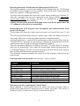
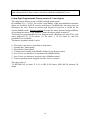
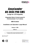
The '2' and '5' keys act as UP arrow (2) and DOWN arrow (5).
Keys ‘2’ and ‘5’ scroll texts and letters up and down.
If we visualize a top-down list, where the first entry (1) is at the top and the last
entry is at the bottom, and then the DOWN arrow will move towards the bottom (the
last entry) while the UP arrow will move towards the top (the first entry).
Thus, pressing repeatedly the ‘5’ - DOWN key, texts for zones 1,2,3... will be
displayed. If we currently see the text for zone 7, pressing the ‘2’ - UP key will
bring the text for zone 6.
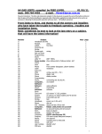
Left
Siren
Select a sentence
from vocabulary
Up
1
Delete
Delay
Delete
Right
Shunt
Display
2
Down
4
Chime
Status
7
5
6
Telephone
Escape
8
Program
Upper/Lower case
Move to next letters group
*
Insert the selected
sentence
Insert (letters & words)
Vocabulary Words
Test
3
Shunt
Erase
0
Reset
Save
9
Edit
#
To enter Editing Mode
type 900 and #
Figure 4: Keys functions in text Edit mode
After entering location 900, the two Leftmost LEDs are blinking indicating that you
can select the text to edit (as in the programming mode we had to enter a location).
To select the text for editing, press the '#' (enter) key. Refer to step 2 in next
paragraph.
Step 2: Editing a text
When entering this step, the lower display line will be cleared, the three rightmost
LEDs start blinking and a cursor ('_') will appear at the first position of the upper
line.
To navigate from one position to another, use key '1' to move left, key '3' to move
right.
Step 3: Modify a character at the cursor
To modify a character at the cursor scroll up and down the available characters
(starting at Space and ending at '<-'). Key '2' scrolls up and key '5' scrolls down.
Refer to figure 3.
Again, visualize the alphabet as a top down list with the letter A at the top and the
letter Z at the bottom. Key '5' scrolls down from A to Z, key '2' scrolls up from Z to
A. The scrolling starts at the current character. This means that if we have at the
cursor the ‘a’ character, pressing the DOWN key '5' will bring the letters 'b', 'c', 'd'
etc. Keep the UP or DOWN keys pressed for a while, the scrolling will become
faster.
8
To reach the required characters range, use the '*' key. By repeatedly pressing '*' key
we jump from one range of characters to another in the order: 'space', '0', 'A', 'M', 'a',
'm' and space again (starting from the current range in which the character at the
cursor is now).
Moreover, to change a letter case (UPPER<>LOWER) press key '8'.
To insert a space at the cursor press the '6' key. A space will be inserted and the text
at the right of the cursor will be moved to right, some characters in the line will be
lost when moving over the end of the display.
To delete a character at the cursor press the '4' key. The character at the cursor will
be erased and the text at the right of the cursor will move left to adjust for the lost
character.
"Word Erase" key is available, '0' key erases all the characters from the cursor to the
next space at right.
Thirty - (30) words vocabulary is included. Pressing key ‘7’ can access the
vocabulary. After pressing key '7', the words displayed at the lower line.
To brows, use the ‘2’ (UP) and ‘5’ (DOWN) keys, once the required word appears,
press '6' (INSERT) key. The word inserted at the cursor and the cursor will be
positioned after the inserted word. If no word selected, just press '9' (reset) key to
exit the vocabulary word selection mode.
Pressing key ‘8’ at the cursor replaces Upper to Lower case letters and vice versa.
After inserting, deleting, adding word from the vocabulary you have two options: To
save the new text or to exit the editing mode without saving, save the new text by
pressing '#' (enter). The Keypad local memory save the text, sent to the control panel
and echoed from the control panel to connected keypads.
To exit without saving the modifications, press '9' key (reset) that functions as
Escape in Editing Mode.
After saving or exiting without keeping the changes, we are back to step 1: Text
selection.
The LOGO texts follow the last zone text. Pressing ‘*’ and ‘0’ simultaneously
display the Logo.
To exit the Editing Mode press '9', keypad returns to Installer
Programming Mode. To exit the installer programming mode, type “999”
8. Remote Up and Downloading
Select the proper panel type from the menu in the DWLD software. Use the latest
DWLD version software that supports the PRO and Dublo panels.
Latest DWLD version is 3.06 (May 2009), this version provide to up and download
edited texts via PC and Modem.
For PC communication use the AV-232 adapter or PC with dedicated modem, with
the latest EasyLoad software pack.
For AV-232 or AV-USB232: Connect the adapter to the “Serial” plug (located in the
panel PCB upper-right part), enter to programming mode, type 200 and then 77
confirm by #, 4 LEDs will start blinking, “PC COMMUNICATION” is displayed,
then establish connection from the DWLD PC program.
For communication through modem, call the panel via the DWLD program. To
abort communication (during remote DWLD) Hold-down key ‘9’.
9
Note: The AV-707 dark window and AV-706 upper Gray color panel are covered
with a thin protective sheet; remove the sheet when the installation is over.
9. New Eight Programmable Timers (version 2.11 and higher)
The eight timers feature is not available with all alarm panels.
By enabling 074 – 2 (074-5 for version 3 and Dublo), eight programmable automatic
timers are available. In EUR version (with Power-Cut hardware), the timer also can
disconnect the Aux. Power (to sensors and keypad). Power-Cut is useful for the
Jewish Shabbat mode. Separate manual describe the many features and possibilities
of operating the timers. Code number 6 turns the timers mode on and off.
The timers are programmable in User Program mode (Hold-down 8 and 1234), each
timer addressed by 31-38 entries (31 for timer 1, 38 for timer 8), and few
possibilities are included.
The timers operation (mode) can be:
0 - The timer is not active (cancelled or skip timer)
1 - Arming the Control panel
2 - Disarm the Control panel
3 - Control panel Arming with HOME (define Group Bypass zones)
4 - Aux. Power (to detectors) is disconnected (Shabbat mode)
5 - Aux. Power (to detectors) restored (end of Shabbat mode)
6 - Timers operation mode stopped and Aux. Power restored
The entry order is:
3X HH MM M; set timer X (1-8) to HH (0-24) hours, MM (00-59) minutes, M
mode.
10
Arming with Auto Timers Enabled
Arming is performed even with open zones.
Disarming with Auto Timers Enabled
Follow-Me telephone number is not erased after automatic disarming.
If Opening/Closing report to central station is enabled the report is always sent even
if USER 1 was not selected to report. Using CID (Contact ID) format an automatic
Opening Closing is reported.
Automatic timers activation follows the timers order (1->2->3), and not the
chronological order!
That means; if timer 1 is set at 20:00 and timer 2 is set at 19:59, timer 1 operation is
carried first and then (after about 24 hours) timer 2 is called to perform its task.
Timers operation can be enabled/disabled by the user; by entering code 6 (if so
programmed), or from the user-programming mode.
Power Cut mode operation
In the Power-Cut mode the following applies:
- The Power Cut controls the Aux. Power output
- All the zones programmed as Delay Power Up zone (at address 031) are ignored
(so they cannot set an alarm), PIR should be connected to those zones
- In Disarm mode, zones opening will not cause the Status (Green) LED to blink.
The LED will blink only after troubles occurred in the system.
- Chime mode disabled (even if previously enabled)
- All zones treated as Green Zone (No Reset) zones (meaning that Alarm will stop
even if the zones remain troubled).
When this mode is stopped and power-cut is restored, the PIR zone (Power-Up
delay zone type) detectors will be ignored for 40 seconds more (until they warm up).
To display the timers hours
Hold down "0" then hold down "6": display timers.
During the display, hold down the following keys to browse:
"1" - From the first timer
"2" - Backwards
“#” (Enter) - Next (after the 8th will start again from the first)
"9" - stop display
- Arming by timers: Two long beeps - unless it is arming with group bypass (home)
and there are group-bypassed zones
- Disarming by timers: Three short beeps (if enabled by programming)
11
10. AV-707B (supported by PRO & Dublo panels version 2.16 and higher)
System
3
Disarmed
12:00
*
armed status shunt
A
fire
B
The AV-707B is an enhanced version with three
functional buttons. Each buttons automatically
enter to Home Mode A, B, or C and arms the
system.
Optional: Metallic versions type AV-707BG
(Golden) and AV-707BS (Silver), contains the
three buttons.
C
A V-7 0 7B
Functional buttons
Figure 5: AV-707B functional buttons (Arming + bypass and
emergency)
Button A: Selects Group Bypass No. 1 (if programmed so) and arms the system.
For AV-707 (without 3 buttons) press 0 and 1
Button B: Selects Group Bypass No. 2 (if programmed so) and arms the system
For AV-707 (without 3 buttons) press 0 and 2
Button C: Selects both Group 1 and Group 2 and arms the system. Make sure not to
bypass all zones, in such case arming will be without bypassed zones.
For AV-707 (without 3 buttons) press 0 and hold down 0.
To activate the three bypass options, press * then hold-down the function button, the
Orange LED will blink and then the Armed LED will light steady to indicate that
systems is armed.
Address 050-7 enables Panic, Medical Emergency and Fire Alarm activated by the
three buttons. Operative only if the Contact ID format is used to report events to the
Central station. For more details ask for the Emergency Three Panic Keys appendix.
11. Buzzer Control
New feature: The buzzer of each keypad can be turned ON/OFF by holding down
keys "0" and "#" simultaneously.
When the buzzer is ON, it will sound while the keys "0" and "#" are being held
down. When the buzzer is OFF, hold down the keys for 2-3 seconds, sounder
feedback heard in this case only after releasing the keys.
The buzzer set ON at "Power On" and every time the keypad is in programming
mode.
All rights reserved to AV-GAD Systems LTD. April 2009. \\Avgad\SYS\WORDOC_6\AV-707\Manuals\707+707B+706_E_3.04A.doc
Item 4710
12