1
EasyLoader
AV-2004, AV-2048
Integrated Alarm Control/Communicator
Year 2000 ready
Express
Installation and Operation Manual
Version 3.06
Edition I
This product is subject to continual enhancement and therefore
specifications may be changed or altered without prior notice
Item: 4718_2004
www.av-gad.com
1. INTRODUCTION
System planning
When the panel reaches you it will be factory programmed. This is done for testing purposes but
also can be used for installation if required without first entering to programming. This present
program is referred to as ‘Factory Defaults’.
This is a short format manual. Make sure you are familiar with all the features
and options before attempting to install and program. Refer to the full version
manual (AV-2005/8 full version), this manual includes glossary and more
details. For PRO type, panels refer to the AV-705/707 manual.
System supplied with or without transformer according to approval requirements in each country.
Order the keypad transformer separately (few types available). Blinking ‘h’ after power-up,
reminds to adjust system’s clock and date (see page No. 10). Default arming code is 1, 2, 3, 4.
Version 3.00 (“D” Suffix): New and improved PCB, DTMF control (arm, disarm, etc) option
with “D” panels, PRO panels available, panel version identifies itself as AV-2004/48D (EasyLoad
software), self test at initialization (STI) - Dial LED blinks for the first 50 seconds after power on,
new factory defaults, address 052: Set the CS signal test per days, remote text transfer for PRO
panels. RS-232 and SVM sockets added. Home Automation features for remote control of output
A1. Version 3.02: First alarm indication by DTMF, A1 at Latch mode. Version 3.04: New at
072-4, activate ON output to drive ADSL filter line disconnect, added 999 to exit programming
mode, during Answer Now mode keypad display CA, telephone line monitor intervals (add 094)
changed to minutes. 3.04A: Zone 4 or 8 as aux. Key. Version 3.06: AV-2048D new zone wiring
at 075-2, new feature: Enable – Keypad & Sir sounds at Home mode at 075-1.
Electronic Fuse Overview
The Electronic Fuse device is installed as a series element in a circuit. In response to an over current it protects the
circuit by going from a low-resistance to a high-resistance state that reduces the current to a level that’s safe for the
circuit elements. The change in resistance is a result of a rapid increase in the temperature of the device. Like
traditional fuses, Electronic Fuse devices interrupt the flow of dangerously high current. However, unlike traditional
fuses, they automatically reset after the fault is cleared and power to the circuit is removed. Because they are solidstate, Electronic Fuses are also better able to withstand mechanical shock and vibration, and provide reliable
protection in a wide variety of applications. In case of over current, carefully touch the fuse body (yellow round disc),
hot body means the Electronic Fuse in protection mode, disconnect the load and wait 2-3 minutes until the fuse
body get cooler.
2
2. MOUNTING THE CONTROL PANEL
Refer to detailed wiring diagram. Note: ‘h’ is displayed after power-up to remind installer to set
the time; ‘h’ will be removed after time setting (by using keys 0 and 1 refer to page 10).
Select a mounting location as following:
1. A continuously powered (non-switched) AC power source, compatible with step-down
supplied transformer. Make sure the mains (110 or 220V) are fused.
2. A cold water pipe Ground, ideally no more than 3 meters (10 feet) from the panel. Use 16
AWG or 0.5 mm2 wires.
3. Telephone line socket.
Always install the control panel box in a hard-to-access location
Locate one of the Keypads near the Entrance/Exit door. Install a tamper-switch to secure the
control panel box. Connect the tamper-switch to a 24H zone (is active at all times).
Zone Wiring Mode:
Your system provides few ways of zone wiring: Non EOL resistor loop, EOL resistor loop. The
EOL loop protects the zone lines against tampering. It’s recommended to use the EOL mode; it’s
safer and keeps lower EMI and RFI interference.
Via programming, select either End-Of-Line (EOL.) resistor protection, or non-EOL mode. The
EOL is defined at address 029; the default program is set at non-EOL for all zones. To select EOL
mode enter at address 029 the required zone to be EOL, or enter ‘0’ to enable all zones as EOL.
Note: Address 029 at the AV-2048 is blocked. Only EOL mode is available.
If EOL mode is selected (recommended), install the EOL resistor (2.2K/0.25 or 0.5W) inside the
detection device (e.g. PIR, Magnetic Switch). Maximum zone wiring length is 200 meters
using 0.5-mm2 wires, EOL mode wiring is highly recommended.
Note: ‘Zone’ and ‘Sector’ are interchangeable terms in this manual.
Always use EOL resistor, to prevents EMI and RFI interference and higher security
An EOL zone will report Tamper alarm in case of zone shorting (if it has been EOL
programmed). For connecting N.O. zones, programming is required, refer to address 042. Do not
connect few sensors to one zone in EOL mode.
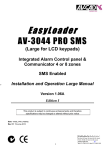
AV-2048, eight zone panel zone wiring
The AV-2048 board looks similar to the AV-2004, the AV-2048 board carries a specific
identification label. The hardware and software are different.
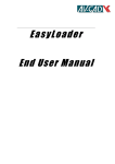
The AV-2048/D works in EOL mode (can’t work in none EOL), it means always using EOL
resistors. The zones are referred to –V. Connect two wires to the same terminal, one wire in series
with the 2.2.K resistor and the sensor contacts (relay), the other wire in series with 4.7K resistor
and other contacts. Refer to figure 1. Tamper alarm per zone is not available with AV-2048.
3
The 2.2K resistors are wired with the odd zones (1, 3, 5, 7), the 4.7K are wired with the even
zones (2, 4, 6, 8) as table below shows, for latest AV-2048 starting version 3.05.
Terminal wire No.
1
2
3
4
Resistor 2.2K
Zone No. 1
Zone No. 2
Zone No. 3
Zone No. 4
Resistor 4.7K
Zone No. 52
Zone No. 6
Zone No. 7
Zone No. 8
+12V -V
-V
1
Zo
5+ ne
6
Zo
7+ ne
8
Zo
1+ n e
2
AV-2048/D Wiring
(by Default)
Zon
3+4 e
Version 3.00 to 3.04
2
PIR 1
2K2 Resistor Colors
Red, Red, Red
2K2
Display
Zone 1
3
4
-V
PIR 2
-V
4K7 Resistor Colors
Yellow, Violet, Red
4K7
Display
Zone 2
Figure 1: Optional zones wiring in AV-2048D from version 3.05 (left side)
Very Slow Response Zone
This feature removed starting version 3, not available with “D” pales.
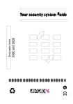
3. KEYPAD WIRING
Up to two AV-701T/TI or four AV-702 Keypads can be connected to AV-2004/48 Control Panel.
When few keypads are connected, wire each one directly to the panel, not from one keypad to the
other. Refer to drawing in next page.
Important Note: Up to two (2) AV-701T/TI or four (4) AV-702 Keypads can be connected to
AV-2004/48 Alarm Control Panel
When using few keypads connect them in parallel. Each keypad has four terminal wires:
¾ (+) Power, connect to + Aux. Power ¾ System Data, connect to OR
¾ (–) Power, connect to – Aux. Power ¾ System Strobe, connect to YE
Panel
Panel
Wrong Wiring
Correct Wiring
Figure 2: Wiring more than one keypad
4
When a non-blinking ‘8’ is displayed and keys do not respond, it is an indication that the
keypad is not communicating with the panel. Check wiring and polarity
•
•
•
Wire length for each AV-701 Keypad should not exceed 100 meters (when using 0.5 mm2
wires).
For longer than 100 meter keypad wiring, contact manufacturer's consultant. For AV-701TIP
(with tamper) run five (5) wires. Connect the TMP terminal to a 24H or Tamper zone.
Power at Keypad should be a minimum of 11.5 Volts.
IMPORTANT! Never run Keypad wires alongside telephone wires, high voltage wires, or
transmitting antennae. Wire the keypad wires separately and not in same cable with other
devices (telephone, PIR etc.)
For proper connection, refer to wiring diagrams at the end of the manual.
4. SIRENS
•
•
•
•
•
•
•
•
•
The control unit contains single siren outputs, protected by Electronic Fuse.
Siren should be of an outdoor type with a minimum power of 15W, 8 Ohms Impedance.
Enclose the siren in a metal housing, with anti-tamper switch protection.
Siren mode is factory default, in Siren mode install only speaker-type sirens, which DO NOT
contain sound driver or electronic modules.
The alarm issued by the siren differs according to the type of zone.
‘Bell Mode’ converts Siren outputs into 13.6V DC outputs (no sound is issued). Bell mode
is applicable for driving self-powered sirens or bells, or combined sirens and strobes.
13.6V DC is issued at Bell mode. It’s recommended to use Bella sirens series.
In Bell mode, connect only sirens, which contain sound driver or electronic modules.
Self contain Bell mode is programmable (address 072-1 and 073-3). This mode provides
connection of Bells or Sirens that requires 13.6V at idle and 0V during alarm.
Contact manufacturer's consultant before connecting higher power loads.
To connect self-contained sirens, Bells, and inner-oscillating sirens, Bella siren series refer to
address 072-1 for Bell mode. Bella sirens support internal battery charge and monitor for
higher security.
Warning, Output current for Bell should not exceed 1.0 Ampere
5. AV-2004/48 Remote Indication Terminals
Indication
Application
ON
(-V) on closing (Arming) or if cross-zoning feature selected
A1
(-V) during alarm from the programmed zone
The A1 may be used to drive a low current Strobe Light (Xenon) that consumes up to 300 mA
Home Automation feature: Momentary activation of A1 output for three seconds, via any DTMF
telephone command (address 074-2).
5
In case other features are selected for the same output, this feature is not applicable.
6. GROUNDING – Lightning Protection
The control panel must be earth grounded for lightning protection to work effectively, and in
order to prevent RFI and EMI interferences. Connect the ground to a verified cold-water pipe
using a minimum 16 AWG (or larger) wire. Run the wire via the shortest possible route.
System grounding is compulsory
Connect the Grounding wire to main board and to metal box.
Note: Connect the Ground wire, to the
terminal. This is not a minus (-V).
Be careful of static discharge; before handling the main board touch a grounded metal.
Before grounding the system, make sure to connect ground properly, check that ground does not
transfer high voltages.
7. BACK-UP BATTERY
Make sure to connect the Battery in the correct polarity!
•
The system's Red wire is the positive pole (+) and the Black wire is the negative pole (-).
•
The battery will provide power back up in case of AC power failure.
•
Connect back-up battery to ensure proper operation of the system.
•
Recommended battery: 7 Amperes per Hour (AH), 12V (sealed lead acid) type.
•
A 7.2 AH battery backs up the control panel and a single keypad for approximately 8 hours.
•
AV-2004 and AV-2048 panels accommodates a battery of up to 12V – 7.2 AH (max.).
•
A Electronic Fuse rated at 2.5A protects the battery.
•
Add a power supply for installation with over three LCD keypad and/or if over ten high
current sensors included. Refer to Av-Gad AV-21, AV-40 power supply and charger.
The 4AH–12V battery fits in the ABS box, but the door is too tight, why? Note the following:
1. A small bulge on the box door supposing to hold the battery may displace the battery;
place the battery near this bulge and not on it
2. Make sure that the battery is not laying on the wiring
6
8. TELEPHONE LINE WIRING and PROGRAMMING
It’s recommended to connect the control panel to an independent telephone line, if a device is in
parallel with the alarm panel, this may grab the call first (like a message answer/fax) during
remote up and download. Don’t connect fax or answering machine in parallel on the same
telephone line.
Default dialing mode is DTMF. If Pulse dial is selected, the default is European Make/Break rate
of 40/60 milliseconds (in Pulse dialing).
Dialing mode is programmable (refer to programming sheet addresses 084).
Connect the telephone line to ‘TEL-LINE’ terminal, if handsets connected to same line connect
them to ‘PHONES’, when system attempts to dial the ‘PHONES’ is disconnected.
Do not connect to ISDN or other digital telephone system. Most ISDN converters contain an
Analog line; connect the Analog line of the ISDN to the panel TEL-LINE terminal. For
DSL/ADSL connect a dedicated lien filter supplied by local Telecom Company.
9. BEFORE POWERING UP
•
•
•
•
•
•
•
•
•
Place Control Panel in a well-ventilated location, and as far as possible from any heat source.
Do not place high power RF wireless transmitters near Control Panel.
Check for proper grounding.
Make sure detectors, keypads or any other devices are connected to the Control Panel in
their correct polarities.
Connect a momentary voltage to the siren; making sure a ‘beep’ is sounded. In case of no
beep, check for a short circuit or improperly connected wires.
Power-up through transformer, if system seems to operate properly connect the battery.
Do not connect any sensors or other devices to the battery terminals.
The AV-2004/48 are compatible with 12V smoke detectors, common collector type or relay
(-) output on alarm.
In the AV-2004/48, a momentary switch achieves smoke detector reset. The switch (or relay)
disconnects power to smoke detector following a smoke alarm.
10. AV-2004/48 STANDARD KEYPAD FUNCTIONS
Common Terms in this Manual
‘SHUNT’ Ù ‘BYPASS’ are interchangeable terms
Program Mode Ù Provides features programming, ‘P’ is displayed, alarm is disabled
Use Mode Ù Normal operation mode
AV-701 Ù AV-701T Ù AV-701TI Ù AV-702 are identical and interchangeable term
7
•
•
Short press access standard Keypad functions. The numbered keys (1 to 0) are used for
Arming/Disarming (ON/OFF), Zone Shunt (Bypass), and other operation and programming
functions.
Short beep confirms each key press.
A short press on the AV-701 keypad key accesses the following special functions:
Chime
5
Shunt
0
Shunt
0
Zone Bypass, by pressing key ‘0,’ followed by entering the Zone number.
Zone Bypass via Code (requires programming, see address 071-5).
Press key ‘0’, while 4 LEDs are blinking, enter valid user code; When only 2 leftmost LEDs are blinking, enter zone number(s) to be bypassed, 4 LEDs stop blinking,
‘Shunt’ LED remains on to confirm zone bypass, within 20 seconds enter your user
code to Arm the system.
0 AV-2004: Group Bypass, by two presses on key ‘0.’ Group-Bypass is
then
operative only if System is armed within 20 seconds after entry of this feature. Yellow LED will
flash and ‘h’ (Home) will be displayed for 1 second in confirmation.
AV-2048 Arming with Group Bypass: 2nd Group Bypass added, (address 034) and the
procedure enhanced; after selecting the Group Bypass, system is armed (without code entry). To
bypass 1st group: Press “0” and hold-down “1”, to bypass 2nd group press ”0” and hold-down “2”,
to bypass both groups press “0” and hold-down “0”. Yellow LED will flash; ‘h’ (Home) will be
displayed for 1 second in confirmation, then the Armed LED lights-up in confirmation.
When Group Bypass is selected the Shunt LED stops blinking eight seconds after arming. This
will prevent the LED light from disturbing sleepers near the keypad.
B. There is no exit/entry delay-warning buzzer at the keypad.
C. There are no ‘beeps’ at the keypad until an alarm occurs or Group Bypass is canceled.
D. When the keypad LEDs are turned off after Arming (requires programming), touching the
keypad will turn them on for 5 seconds.
Shunt
0
Instant Arming. Press key ‘5’ (requires programming at 071-2) to Arm.
Shunt
For Group Bypass with code (requires programming); Press key ‘0’, while four LEDs are
blinking, enter valid user code. When only 2 left-most LEDs are blinking, press again ‘0’ key, ‘h’
will be displayed and, 4 LEDs stop blinking. ‘Shunt’ LED is blinking to confirm Group Bypass,
enter your user code to Arm system within 20 seconds (otherwise Group Bypass will be
removed).
8
11. AV-2004/48 HOLD-DOWN FUNCTIONS (AV-701, AV-702 SERIES)
To access the hold-down functions hold down the key for approximately 2 seconds.
•
Holds down functions are confirmed by a prolonged beep.
Hold-Down Functions:
•
Siren
1
Shunt
Display
2
Status
3
Delay
Delete
4
Chime
5
Telephone
6
Key 1 Î SIREN TEST
Key 2 Î SHUNT DISPLAY
Displays shunted zone(s).
Key 3 Î STATUS DISPLAY
Displays troubled or malfunctioning zone(s).
Key 4 Î DELAY DELETE (INSTANT PROTECTION)
Holding-down key 4 cancels Entry Delays in zones selected as ‘Delayed’ zones. All
zones become Instant.
‘d’ is displayed in confirmation. Instant Protection becomes effective only if System
is armed within 20 seconds following hold-down of key 4.
Key 5 Î DOOR CHIME
Enable Chime mode. Door Chime operates on Chime-programmed zones.
Hold-down key 5 enables and disables the function; chime mode is not affected by
Arm/Disarm.
Chime mode is confirmed by ‘c’ display on keypad.
Key 6 Î DIALER TEST & FOLLOW-ME PROGRAMMING
Test is performed in ‘Disarmed’ mode.
Function
Via AV-707 Series Keypad
Displays Programmed Follow
Me Telephone Numbers Without
Dialing
Follow Me telephone number
programming
Via AV-701 Series Keypad
Hold-down [6]
Hold-down [6] then holddown
[6] again
Hold-down [6] then holddown
[7]
Programmed Telephone number
Verification (Display and Dial 4
telephone numbers)
To display the programmed telephone numbers without dialing hold down key 6; within a few
seconds, ‘c’ will appear on the display, followed by the (programmed) ‘Follow Me’ telephone
number.
When programming telephone numbers that requiring an inter-digit delay (‘Pause’) during
dialing, Hold-Down key [0], a momentary ‘P’ will be displayed (Delay duration is 3 seconds).
The ‘Follow-Me’ number will be displayed, or displayed and dialed, followed by display-and-dial
of up to three additional telephone numbers.
9
Telephone
6
Test
7
1
then Siren
Address 092 enables ‘Answer Now‘ feature (answers remote computer
after 1 ring). The user attending the control panel can reduce the number of rings before answer to
one ring. To cancel the Answer Now feature hold-down 6 and hold-down 0.
This feature is useful if the control panel was programmed not to answer incoming calls
(programming of 21 rings or greater at address 091). For ‘Answer Now’ to be available, program
01 at address 092.
User should hold-down key 6 and then key 1, before the call is made to the control panel. The
panel will acknowledge the command with two beeps and ‘A.’ is displayed. The feature remains
active for 5 minutes after entered, enabling programmer (at remote computer) to enter the panel.
•
•
•
•
•
•
Key 7 Î FAULT FIND
Fault Find enables testing of all detection devices.
Fault Find mode can be entered only during the 15 seconds following system Disarm.
24H, Fire or Panic alarm will stop Fault Find mode.
Hold down key 7, confirmed by ‘F’ on Keypad display.
Open and close each zone to test. A one-second beep confirms detection of zone opening.
Three beeps indicate zone closing.
Quit Fault Find mode by arming the system.
Program
Reset
8
9
1.
2.
3.
4.
Key 8 Î PROGRAM
Key 8 accesses ‘Program’ mode and user code programming (changing).
Key 9 Î RESET
‘Reset’ performs the following functions:
Cancels last Keypad entry
Stops the communication test (triggered by hold-down key 6)
Resets Day Zone Alarm at Keypad
Exits Programming mode (features, telephone numbers, etc.), or type 9,9,9 to exit
programming mode (active in LED and PRO panels).
Key ‘0’ Hold-Down functions
0 Key 0 Concise Alarm History: Hold down key ‘0’ to display the last alarm
1.
sequence. New alarm will create a new history instead of the old one.
Shunt
0 and
0 Detailed Events History (requires programming): Hold down key
2.
‘0’ and again hold down key ‘0’ to display up to 36 events, including: System opening and closing
by user number, opening or closing time, zone caused alarm, AC fail.
Shunt
Shunt
0 twice, three LEDs start blinking to indicate a special operation
By holding-down key
mode. The events are being displayed from the most recent to the oldest event.
The event is displayed as following:
Shunt
10
XX - Event number (from 01 to 36), then HH_MM (Hour and Minutes) Event Time, Event (alarm
or opening/closing). More events are reported in the PC up and download log events.
Translate the display as following:
‘u’ (user number 1 to 8)
‘o’ or ‘c’ - opening or closing
Zone causing alarm-Will blink twice
tX - Tamper alarm form zone causing alarm (X)
H - Means Panic Alarm
Note: 3 lines (≡) indicates power fail. In history events AC fail is displayed.
For example:
Zone no. blinks twice
01 2 2 _ 2 4 u 1 o
02 2 3 _ 0 5 7 7
03 2 3 _ 3 5 H H
- Sign then long beep
indicates end of History
04 0 0 _ 0 8 u 1 c -
Display
Event 01
Time
User 1
Opening
Event 2 Time Alarm Zone 7 Event 3 Time Alarm Zone H Event 4 Time User 1 Closing
During zone number display, keypad display blinks twice to indicate the zone number.
Browsing through Events History
Keys used for browsing:
Shunt
Display 2
¾ Skip forward to next event
5 ¾ Display again current event
8 ¾ Skip backward to previous event
9 ¾ Cancel History Event Mode and exit
When last event is displayed and attempting to move forward (key 2) a blank sign ‘–‘ is displayed
and a long warning beep indicating that it is the last event. Press key 8 to move backward, if no
key is pressed Event History stops and system returns to Use mode.
When starting History Events mode the events are displayed from starting to the end without any
break, until any browsing key had been pressed.
Chime
Program
Reset
During History Event browsing, system will respond only to alarm or panic, Arming denied.
Alarm or Panic during History Event mode will quit this mode and system will set to Use
Mode (normal operation mode. Clearer History events are available when using the
download.
3
0 and Status Concise History of Tampered Zones: Hold down key ‘0’ and then
3.
hold down key ‘3’ to display the Tampered zone alarm sequence.
New alarm will create a new history in place of old history.
Shunt
1
0 and Siren
4.
Display and Setting of System Time: Hold down key ‘0’ and then
hold-down key ‘1’, three LEDs are blinking, wait for the display of system time in 4-digit format.
To set new time, hold down key ‘0’ and then hold down key ‘1.’ Do not wait for time display;
enter the new time in 24-hour format.
Shunt
11
The local clock time is not stored in system memory; clock must be adjusted after power-up.
System time is reset to 00:00 after power-up, ‘h’ will be displayed to remind user to set time, ‘h’
will be removed after setting new time.
Shunt
0
Shunt
Display
2
5.
then
Display and Setting of System Date: Hold down key ‘0’ and then
hold-down key ‘2’, 3 LEDs are blinking, enter date; ‘dd mm yy’. When history displayed at
keypad, time is displayed. The up and download PC software synchronies time and date.
The local date is stored in system memory; date must be adjusted after long power-fail.
Years 78 through 99 translated as 1978 to 1999
Years 00 through 77 translated as 2000 to 2077
6. Reset Events Memory: In program mode press 200 then 04 to erase all events from memory.
5
0 then
7.
Display Last 2 Users: Hold down key ‘0’ and then hold down key 5
to display user number and System opening or closing time.
‘o’ is displayed for Opening (Disarming); ‘c’ is displayed for Closing (Arming).
Shunt
Chime
0 (do not hold-down) and press
8.
cancel all Bypassed Zones.
Shunt
*
Keypad Panic
Reset
9
(do not hold-down), will display ‘-’ to
#
Keys Î PANIC BUTTON
Holding down * and # keys will trigger Panic alarm. H will be displayed (zone ‘H’). For Silent
(used with Panic button) Panic alarm, remove siren and buzzer activation by programming the
Panic Zone so. Panic zone program as 24H zone type, N.O. type, fast response type.
To quit zero hold-down functions, hold-down ‘9’
To cancel Hold-Down function accessed by keys [0], [6] and [7]; Hold-Down key 9 (Reset)
12. SYSTEM CODES
Up to eight Arm/Disarm codes and one installer (dealer) code are available; each code contains
one to six digits.
Do not use ‘0’ as the first digit in a code.
Do not use ‘5’ as first digit in a code number if Instant Arming via key 5 was program.
The user(s) code must not start with the same numbers as the installer programming code (1994).
Do not use same codes or same first digit for few codes, for example; if code of user one is 1,2,3,4
avoid programming code of user two to be 1,2,5,6.
1. Default Arming and Disarming Code ‘1 2 3 4’ (Code No. 1) - Use ‘1234’ as Arming
Code (also called Owner Code). Use code No. 1 to program a new user code.
Upon setting new Arming & Disarming code, the default user code ‘1234’ is automatically
replaced. For setting system codes to default, power up by applying AC and battery and
#
* Keypad Panic
immediately hold-down keys
, after 2nd beep release keys, in
confirmation ‘U’ blinks 3 times.
2. Code number 8 as Visitor Code (requires programming) – Program the Arm/Disarm Code
No. 8 as a ‘one time code,’ for employees and one-time visitors.
12
This code is valid 30 seconds from Arming. After 30 seconds, the code is not valid. Entering
code No. 8 will delete zone bypasses including auto-bypass.
3. Code number 9, Programming Code (Installer Code). This code enables entering the
programming mode (system features programming) at the Installer level.
The factory default programming code is ‘1 9 9 4’.
The programming code may be installer-programmed. Installer Code does not Arm or
Disarm system.
4. User Codes - (Arming/Disarming code); each code is 1 to 6 digit. System provides eight
users programmable codes.
13. Remote Key and Wireless Arming & Disarming
The AV-2004/48 enables Arming and Disarming by remote momentary or latch key-switch (as
programmed in address 071-7), which is connected to JP1 ‘KEY’ and ‘- Aux. Power (Refer to
Wiring Diagram). Cable set for connecting to JP1 requires order separately.
When using remote key-switch, wire length should not exceed 10 meters.
A Momentary pulse (momentary trig) between ‘KEY’ terminals will Arm and Disarm the control
panel (close the ‘instant’ and ‘24H’ zones Prior to arming.)
System reverts to previous status with next momentary pulse. (Refer to Wiring Diagram.)
For Arming/Disarming via Wireless Radio Remote, connect receiver's relay to ‘KE’ and ‘-Aux.
Power’ terminals. Verify the receiver relay mode, momentary, or latch, and set system
accordingly.
For fast Remote Key wiring, the AV-2004/48/M contains a fast-insert connection, a dedicated
wired connector is available (not included in the standard AV-2004 and AV-2048).
In most cases the Key connector is applicable for emergency Disarming – Short the key terminal
with screwdriver. For remote arming with wireless remote transmitter use the A..RX and AVS22.
Starting version 3.04: Zone 4 or 8 may function as auxiliary remote key input, programmable at
address 050-3. The Aux. key Arms without Home (group) mode, sounds siren beep when Arming
(if programmed), sounds siren beeps when Disarming (if programmed).
14. Remote Access via DTMF
General Description
Starting generation III alarm panels (“D” suffix) includes the added functions for remote control
via DTMF phone. DTMF commands are possible when the panel call your phone, or by calling
the panel. The DTMF remote control functions:
Î Check the status of the control panel (Armed/Disarm, Alarm in progress)
Î Arm or disarm the control panel
Î Bypass zones or clear all bypassed zones
Î Stop the dialer report during alarm
Î Momentary activate A1 (alarm) output for three seconds
Î First Alarm indication - by a number of beeps per zone, special tune for Panic alarm
The same options are available when a call is received from the control panel during an alarm
condition.
13
To enable the DTMF control program address 074/6 “Enable remote access by telephone”, and
074 - 2 “Enable A1 activation by telephone”.
Keypad online conformation and DTMF functions history
When the control panel detects the first DTMF key, five short beeps sound at the keypads. The
keypad activation shows the user at the remote site that a DTMF connection takes place (in case
of mistaken connection or similar).
During the remote access the keypad display 'd' and all LEDs blink fast from time to time.
When the call ends, the three short beeps sound at the keypads. When the user code is in process,
the keypad display shows a line for each code number entry (disclose the code), then each DTMF
number pressed show the received number. History log: Each call, confirmed by a valid user code,
is recorded in the events history. Each "Arming/Disarming" is recorded in the events history.
"Last users" history will display 'ut' for "user "telephone, followed by the User number.
Notes: 1. The keypad buzzer or other loud sounds may jam your DTMF entries, in case the
keypad is close to your DTMF telephone, during testing disable the buzzer.
2. When entering the DTMF commands wait for “quit” period, if entering commands
during the system confirmation tunes, or other tunes the panel may miss the DTMF entries.
The panel calls the user during alarm
When the control panel calls the user during alarm, it will first generate the siren sound for about
30 seconds (to shorten this feature at address 085 “Tel. Message Time”, to 30, as default is 50
seconds). The siren sound will stop ten (10) seconds before the end of the call and a greeting tune
will be sounded, after the greeting tune enter your code followed by #. To stop the dialer enter 6#,
to get panel status enter 7#, to disarm the panel enter 2#. To end the process press 9#.
The control panel will answer the call after the number of rings programmed at address 091 (or
following the “bypass answering machine" procedure).
Commands
Each command must be followed by the '#' key (Enter) in the remote phone. The control panel
waits 4 seconds between the keys typed. When this time expires, previous keys input will be
discarded.
The key '*' cancels previous input. It’s recommended to start with "learn" function [8X #] to
identify the various confirmation tune.
The commands:
[0 X #] - Bypass zone (# is the Enter key)
X is Bypassed zone 1 to 8
To clear all bypassed zone: 0 9 #
The zone bypass command is valid only when the system is in Disarm position and not in Alarm
position.
[1 #] - Arm control panel. The control panel will be armed even with open zones. After the
arming, a confirmation tune followed by an "armed" tune will be sounded ("Armed" tune: Short
beep followed by a long tone.).
The user can wait a few seconds to be sure that no alarm has been caused by open zones. In this
case, an Alarm tune (siren sound) will be sounded.
14
[2 #] - Disarm control panel. The control panel will be disarmed. A confirmation tune followed
by a "disarmed" tune will be sounded ("Disarmed" tune: Five short beeps).
[31 #] - Activates A1 output for 3 seconds (enabled by programming 074-2)
[6 #] - Stop dialer. The dialer will stop calling the programmed telephone numbers. This will
affect only the current dialing process. A new alarm will re-start the dialer.
Note that if the user answered a call from the panel or called the panel during a dialing period
without Arming/Disarming/Stopping the dialer, the dialer will restart the cycle from the
beginning.
[7 #] - Check control panel status. The control panel will answer with an Armed or Disarmed
tune followed by an Alarm tune if it is in an alarm condition.
[7 and 7 #] - First Alarm zone, beeps count for the zone number. Report user the zone that
caused alarm. Arming or Disarming clears the First alarm zone reported by DTMF.
[8X #] - Learn function. Using this command, the user can become familiar with the various
sounds used by the control panel in the remote access procedure. Further details find in the
dedicated paragraph. (X - The required sound).
[9 #] - End call. The control panel will sound a confirmation tune and will hang up.
15. USER CODE PROGRAMMING
Set New USER-CODE
8
1. Hold down key
2. While 4 LEDs are blinking, enter code No. 1 (default 1, 2, 3, 4)
3. If code is valid, four LEDs will stop blinking, and ‘u’ will be displayed
4. The two left-most LEDs blink to indicate that the system is waiting for a new user code index
(user 1 to 8) to be entered.
5. Enter the code index (1 for code No. 1; 2 for code No. 2, etc.)
6. The two right-most LEDs blink to indicate that the system is waiting for a new code
(1 to 6 digits) to be entered. Not entering a user code is, voids the code.
7. Enter the new code; ‘U’ is displayed for confirmation.
8. To quit code setting hold-down key ‘9’.
Set new USER-CODE in Installer program mode
1. While system is in program mode, enter address 099, ‘u’ will be displayed
2. The two left-most LEDs blink to indicate that the system is waiting for a new user code index
(user 1 to 8) to be entered.
3. The two right-most LEDs blink to indicate that the system is waiting for a new code
(1 to 6 digits) to be entered. Enter the new code.
4. At Installer program mode, Installer Code (code no. 9) can be set. Installer Code index number
is ‘9’.
5. Upon code setting completion, system reverts to Disarm mode.
Delete a USER-CODE
8
1. Hold down key
2. While four LEDs are blinking, enter code No. 1 (default 1, 2, 3, 4)
3. If code is valid, four LEDs will stop blinking, and ‘u’ will be displayed
Program
Program
15
4. The two left-most LEDs blink to indicate that the system is waiting for a new user code-index
(user 1 to 8) to be entered.
5. Enter the code index you want to be delete (1 for code No. 1; 2 for code No. 2, etc.)
6. The two right-most LEDs blink to indicate that the system is waiting for a new code.
If user code is not entered, the code is voided; short sounder beep confirms code has been
deleted.
7. It's possible to enter a new code; ‘U’ is displayed for confirmation.
8. To quit code setting hold-down key ‘9’.
Auto Arming (version 2.09 and upper)
Programming the time for Automatic Arming:
- By Installer: Program (or display) hours and minutes at address 016.
- By User: Enter to user programming mode. Hold down '8' ('A' is displayed); type hour and
minutes in 24 hours format. To display, hold down '8' and wait. To disable Automatic Arming
program 0000.
After Automatic Arming is programmed, the system time can be set only via User Programming
Mode: Enter User Programming Mode (hold-down 8 and 1234), hold down '1' ('t' is displayed)
and type hour and minutes. Hold down '1' and wait for the time to be displayed. Holding down
keys '0'+'1' to program the time is possible only if the Automatic Arming is disabled (otherwise an
'Error’ warning is displayed).
16. CROSS ZONE FEATURE (AV-2004 only)
This feature removed starting version 3, not available with “d” panels.
16
17. AV-2004/48 Programming Sheet Version 3.06
Factory Default Program is as shown in table; Blank Square means no default program
c TELEPHONES
Tel. 1
010
SIGNAL & AUTO ARMING TEST TIME
Tel. 2
011
Tel. 3
012
Tel. 4
013
Time
Auto Arm Time
014
016
(00:01)
00:00
Test signal to central station (014), enter time in 24 hour format.
Codes are defined at Addresses: 052, 073, 237, 255.
Tel. 1 is also ‘Follow Me’. Maximum 16 digits + 4 pauses each
Tel. Number. Tel. 2 and 3 are communicator option.
To insert * in the phone number; Program system to dial in DTMF, Hold-down keys # and * (as panic), ‘A’ will
be displayed. For Pause during dialing, hold-down key ‘0’.
Zones 5-8 are applicable with AV-2048
d ZONE FEATURES
Feature
Address
1
Fire zones
019
Zone In Use
020
1
Entry/Exit Delay 1
021
1
Entry/Exit Delay 2
022
Entry / Exit Follower
023
24-Hours Zone
024
Day Zone
025
Green Zone (one shot alarm)
026
1
Swinger Shut-Down
027
Chime
028
1
NO-EOL Resistor (not @ 2048)
029
1
Enable Zone Tamper (not @ 2048)
030
Delayed Power-Up
031
Fast or Very Slow Response
032
Group Bypass I
033
Group Bypass II
034
Manual Bypass
035
1
Siren Out
036
1
Alarm 1 (A1) Out
037
1
Reserved
038
Reserved
039
Dial on Alarm
040
1
Sounder on Alarm
041
1
N.O. (normally open) zone
042
Panic Zone
045
Values marked with ( ) are the factory default programming
Keypad Panic Alarm
Siren on Panic
Alarm 1 On Panic
Zone 4 / 8 (2048) as aux. key
Reserved
Telephone Report
Enable buzzer on Panic
Enable buzzer on Panic
2
3
4
5
6
7
8
2
3
4
5
6
7
8
2
3
4
5
6
7
8
2
3
4
2
2
2
3
3
3
4
4
4
5
5
5
6
6
6
7
7
7
8
8
8
2
2
3
3
4
4
5
5
6
6
7
7
8
8
2
050
1
2
3
4
(5)
6
7
Tamper Alarm
Tamper zone as 24H zone
A1 on Tamper
Tel. Line Test at Disarmed
Reserved
Tel. Line fail activates buzzer
Tel. Line fail activates siren
Dialer Report AC Power Fail
051
1
2
3
4
5
6
7
Add. 052, CS test day: 1 - Sun 2 – Mon, 3 – Tues, 4 – Wed., 5 – Thu., 6 – Fri., 7 – Sat., 8 - All week's days, 0 – Clear all
e TIME-OUTS
AC fail
report
delay
Minutes
Zone
Response
time
m. Sec
058
1
Entry
Delay 1
Sec's
059
0
0
060
5
1
2
Entry
Delay 2
**
Sec's x
4
061
0
0
Exit
Delay
**
Sec's x
4
062
0
8
Siren
Time
ON
Siren
Time
Sec's
Minutes
063
0
OFF
Siren
Time
Sec's
064
4
1
A1
Time
Reserve
d
Chime
Time
Abort
Delay
Sec's
-
Beeps
Sec's
065
5
0
066
4
3
067
0
0
068
0
0
069
3
0
4
Note: Address 059 adjusts the response time of zones selected as ‘Fast Response’. If Slow Response selected, the value in address
059 is multiplied by 4 and units are seconds, 63 is the maximum.
17
f SYSTEM FEATURES – Values marked with ( ) are the factory default programming
Feature
Enable-Siren/Bell Test upon Arming
Enable-Keypad 3 Beeps upon Disarming
Enable-Buzzer upon Entry Delay
Enable-Keypad Tactile Beep
Disable-4 LEDs display during Armed
Enable-Battery Test upon Arming
Reserved
Enable-Keypad Panic
070
1
(2)
(3)
(4)
5
(6)
7
(8)
Feature
Enable-Erase F. Me number on Disarm
Enable-Instant Arming via Key 5
Enable-Buzzer during exit delay
Enable-Display Alarmed Zone during alarm
Enable-Manual Bypass via Code No .1
Enable-Lock in Armed after Tamper Alarm
Enable-Momentary Key-Switch
Enable-Code ‘8’ as one time code
071
1
2
3
4
5
6
(7)
8
Feature
Enable-Bell mode
Enable-Detailed alarm history
Enable-Report Opening/Closing
Activate ON output for ADSL filter line-cut
Enable-Report bypassed zones at Arming
Enable-Exit delay when delayed zones clear
Enable -’ON’ output as SVM trigger *
Enable-codes reset to default by * & #
072
(1)
(2)
(3)
4
5
6
7
(8)
Feature
Enable-Display troubled zones at Disarmed
Enable-Test to central station each hour
Enable-Self contain Bell (0V at alarm) **
Reserved
Enable- Group Bypass when Arm with Key
Enable - 2 Siren Beeps at Key Disarming
Enable - A1 output time follows Siren time
Enable - Outputs (A1, ON) 0V at active
073
(1)
2
3
4
5
6
(7)
8
Feature
074
Feature
Reserved
1
Enable – K.Pad & Sir sounds @ Home mod
Enable-Activate A1 via DTMF
2
Enable – 2048 New Zones Wiring Method
Enable-Auto reset zone after alarm timeout
3
Reserved
4
Reserved
5
Enable – DTMF control (D type or Ver. 3)
(6)
Enable – Bypass Answer Machine
7
Enable-Echo Cancellation Tone (AUSTEL)
8
Enable - A1 output as Latching
* AV-2004D starting January 2005. ** Self-contained Bell is operative if Bell mode selected
075
1
2
8
g DIAL PARAMETERS
Pre-Dial Wait Anti-Jam Dial tone Dial
Delay for Dial Delay detection Mode
Tone
Sec's
Sec's
Sec's
080
0 3
081
0 4
082
1 0
Tel.
Min.
Line
Ring
Test
Length
Intervals
Tel.
MSG
Time
InterCall
Delay
00=No 0=Pulses Sec's
01=Yes 1=DTMF
083
084
085
0 1 0 1 5 0
Sec's
086
2 0
Re-Dial Pulse
Pulse
Cycles MAKE BREAK
(max.)
XX
Cycle
087
0 3
Inter
Digit
Delay
5 mS
5 mS
50 mS
088
0 8
089
1 2
090
2 0
Rings Instant
qut'y for modem
modem answer
Tel.
Rings
091
1 0
00=No
01=Yes
092
0
1
Ring
Cycle
Width
100 mS
(1-25)
093
2
0
Rings
Time
Out
Minutes 10 mS Seconds
(Max 99) (Max 20) (4 to 25)
094
095
096
0 0 1
5 0
6
Note address 091: The download is ENABLED by default. Setting 21 at address 091 disable modem (because 21 rings for modem not accepted by
telephone net). To ENABLE enter 01 to 20 at address 091. For Instant Modem Answer (Answer Now): Enter 01 in address 092, hold-down key 6
then hold-down key 1, ‘A’ displayed in confirmation. For special application, address 093 set the ring detector pulse width.
hSET USER CODES: Address 099 provides setting of user codes 1 to 8.
iSET FACTORY DEFAULT: In address 200 enter 6 9, program will revert to factory default programming
18
jCOMMUNICATOR PARAMETERS
TELE
PHONE
Receiver
Reserved
Format
201
0
Frequency
203
0
2
Receiver
Handshake
No. 2
0
TELE
PHONE
Handshake
Format
202
No. 3
0
Reserved
0
Ð
00 - Dialer only (No Communicator)
01 - Ademco, Silent Knight Slow,
Scantronic
02 - Radionics Fast
03 - Sescoa, Vertex, DCI, Franklin
04 - Silent Knight Fast
05 - Radionics, DCI, Franklin Slow
06 - Universal High Speed
07 - Contact ID or Ademco High Speed *
Frequency
204
0
2
Ð
Data
Format
Protocol
Type
207
205
0
0
Data
Format
0
Protocol
Type
208
206
0
0
0
0
0
Sum
Check
(Parity)
209
0
0
Transmit
Inter MSG
Wait for
Rounds
211
0
0
Time
213
Handshake
215
2
0
Sum
Check
(Parity)
210
0
0
Transmit
Inter MSG
Wait for
Rounds
212
0
0
Time
214
Handshake
216
2
0
3
0
3
0
Ð
00=3 X 1
Ð
Ð
Ð
Ð
Ð
00=1400 Hz
00=Standard
00=None
00=2 Rnd
00=0.1 Sec
XX=Sec's
01=2300 Hz
01=4 X 1
01=Extend
01=S.Check
01=1 Rnd
30=3 Sec
02=Hi/Lo
Ademco H.S.
SurGurd
Rec.
set 00 or 01
02=4 X 2
3 Sec's is
Default
03=3 X 2
00 - ‘No Communicator,’ is identical to ‘Dialer’ that generates sound upon alarm. * Contact ID and Ademco H.S. are available at panels version
2.06 or higher. ‘Rnd’ is shortening for ROUNDS. ‘S. Check’ is shorting for ‘Sum Check’. ‘Hz’ is shorting for ‘Hertz’ (frequency unit). When
Contact ID selected program only Group 1 Subscriber ID at address 360 and 364.
k REPORT SELECTION
For communicator codes A to F, enter the following: A=10, B=11, C=12, D=13, E=14, F=15. Note: entering 0 0 , is same as a blank.
Group 1
Group 2
2
2
Report on Alarm
105
3
4
3
4
1
1
2
2
Zone Restore
107
3
4
3
4
½VALUE
1
1
Report Bypassed Zones
109
2
3
4
2
3
4
½VALUE
1
1
½ZONE
½VALUE
½ZONE
Report on Alarm
106
AC LB PA
1
2
3
Control Panel Restore
108
AC LB PA
1
2
3
½ZONE
l ALARM, RESTORE, BYPASS ZONES, OPENING / CLOSING, SIGNAL TEST & FORCE OPENING CODES
Group 1
1
Alarm Codes - Single Codes
2
3
4
110 112 114 116
3
3
3
3
111 113 115 117
1
2
3
4
Alarm Codes - Extended or 2 Digits
Group 2
½Z O N E S
(Alarm Code for Fire = 1)
Alarm Codes - Single Codes
AC LB PA
126 128 130
F
F
2
½CODES¾
127 129 131
9
8
1
Alarm Codes - Extended or 2 Digits
½CODES¾
19
1
Restore Codes - Single Codes
2
3
4
142 144 146 148
E
E
E
E
143 145 147 149
1
2
3
4
Restore Codes - Extended or 2 Digits
½Z O N E S
Restore Codes - Single Codes
AC LB PA
½CODES¾
158 160 162
E
E
E
159 161 163
9
B A
Restore Codes - Extended or 2 Digits
½CODES¾
Bypassed Zones Codes - Single Codes
1
2
3
4
Reserved
½Z O N E S
174 176 178 180
8
8
8
8
½CODES¾
175 177 179 181
1
2
3
4
Bypassed Zones - Extended or 2 Digits
Closing (Arming) Codes-Single Digit
1
2
3
4
220 222 224 226
C C C C
½CODES¾
Opening (Disarming) Codes-Single Digit
Single Digit
Test ½ USER ¾ 1
2
3
4
Test
Force
Opening
236
238 240 242 244
254
256
A ½CODE¾ B B B B
D
221 223 225 227
237
239 241 243 245
255
1
2
3
4
9 ½CODE¾ 1
2
3
4
9
Closing Codes - Extended or 2 Digits
Opening Codes - Extended or 2 Digits
257
In order to disable reporting Closing/Opening change program at address 072; remove value ’3’.
When SIGNAL TEST is enabled, you can specify to report System Status (as default for Extended or 2 digits) by programming for example
‘A’ (Armed) at 236, and ‘D’ (Disarmed) at 254, ‘9’ is the test signal code. For System Status report, select extended or two digits format.
For programming the End-User codes 1 to 8 (Arm/Disarm code) via installer programming mode, enter to address No. 099,
then program new codes by first entering the code index (1,2,3..).
For Force Opening Code (Ambush) the user should enter the Disarming code in reverse order.
cc TEL. 2 - SUBSCRIBER ID NUMBER
Note: For subscriber ID that contains a ‘0’ (zero), enter 10 in place of 0. ‘0’ will be displayed as ‘A.’ Do not enter 0 0.
Group 1
Group 2
Alarm / Restore ID Alarm / Restore ID Open. / Closing ID
260 261 262 263 268 269 270 271 276 277 278 279
To easily program the subscriber ID number, as a sequence of 4 digits use the EASY Program.
Even if your code is 3 digits only you must enter 4 digits, the 4th digit can be any digit and the system will disregard the 4th digit.
EASY Program
EASY Program
EASY Program
Alarm / Restore ID Alarm / Restore ID Open. / Closing ID
360
368
376
20
TEL. 3 - SUBSCRIBER ID NUMBER
Group 1
Group 2
Alarm / Restore ID Alarm / Restore ID Open. / Closing ID
264 265 266 267 272 273 274 275 280 281 282 283
EASY Program
EASY Program
EASY Program
Alarm / Restore ID Alarm / Restore ID Open. / Closing ID
364
372
380
To easily program the subscriber ID number, as a sequence of 4 digits use the EASY Program.
Even if your code is 3 digits only you must enter 4 digits, the 4th digit can be any digit and the system will disregard the 4th digit.
Values beneath addresses are default programming.
1 Auto Bypass is applicable to Instant (Non-Delayed or Non-Follower) zones only.
18. ENTERING INSTALLER (ENGINEER) PROGRAMMING MODE
Easy Tip: You may program any address by entering the address then the value in sequence.
Power up by connecting AC power with or without battery.
1. Hold down keypad key Program 8 (hold-down function).
2. While the four LEDs are blinking, enter programming code (‘1 9 9 4’):
Siren
1
Reset
9
Reset
9
Delay
Delete
4 .
3. If the code is valid, ‘P’ will be displayed. The two left LED's (Red & Green) blink to indicate
that system is waiting for a new programming address number.
4. Enter address to be programmed (see programming sheet). Current value of address will be
displayed, and LEDs will blink.
Note: Blinking of 2 left most LEDs, means system is waiting for new address to be entered;
Enter a 3 or 2-digit address (according to address length.)
Note: 3 blinking LEDs means system is waiting for new value to be entered;
Enter a 2-digit value, or as required.
EXAMPLE 1:
‘P’ is displayed and two left-most LEDs are blinking.
1. Program zones 1 and 4 as ‘Exit/Entry Delayed 1’(zone type).
2. Address 021 represents the ‘Exit/Entry Delayed 1’ zones.
Shunt
1 ; current value of this address is ‘1’ (default program.)
3. Press Shunt 0 Shunt 0 Display 2
Three LEDs will blink and a ‘1’ will be displayed (default program).
Shunt
1 then the new
4. To enter new required value press the address number Shunt 0 Display 2
Delay
1 Delete 4 in uninterrupted sequence; ‘U’ confirms
required value (‘1’ and ‘4’) by pressing
programming updating.
6. ‘P’ is displayed, two left-most LEDs are blinking.
Siren
Siren
Siren
21
EXAMPLE 2:
1. To program zone 4 as 24H zone (in default program, this is an Instant Zone).
2. Address 024 represents the 24H zones
Delay
Shunt
3. Press Shunt 0 Display 2 Delete 4 ; current value of the address is ‘-’ (‘-’ means blank - no 24H zone is
programmed). Three LEDs will blink and an ‘-’ will be displayed (default program).
Delay
Shunt
4. To enter new required value press the address number Shunt 0 Display 2 Delete 4 then enter new
Delay
value ‘8,’ by pressing Delete 4 (zone 4).
‘U’ confirms programming updating.
5. ‘P’ is displayed; two left-most LEDs are blinking.
Note: To delete a programmed feature, enter ‘0’ at feature’s address
EXAMPLE 3:
1. To program zone 1 to 4 as “Fast Response Zone”.
2. Address 032 represents “Fast Response Zone”.
Shunt
3 Display 2 ; current value of the address is blank;
3. Press Shunt 0
three LEDs will blink and ‘-’ will be displayed (- means blank; no Fast Response Zone is default
program).
Shunt
3 Display 2 then enter new
4. To Enter new required value press the address number Shunt 0
Delay
Shunt
1 Display 2
3 Delete 4 .
value 1 2 3 4 by pressing
‘U’ confirms programming updating.
5. ‘P’ is displayed, two left-most LEDs are blinking.
Status
Status
Siren
Status
19. RESET SYSTEM TO DEFAULT PROGRAMMING
Warning! This function erases all codes and system programming settings.
1. Enter program mode.
2. Go to address 200 and enter ‘6’ and ‘9’. Display will show E P R, and system will revert to
factory default program. Code No. 1 is 1 2 3 4; programming code will be 1 9 9 4.
Quitting and Updating new Programming via AV-701 Keypad
9 .
Upon programming completion, hold down key
Wait for a long beep, and then release the key.
When ‘P’ is no longer displayed, the system has reverted to Disarmed mode.
Reset
Note: The system disregards erroneous or conflicting programming features upon quitting
program mode. For example: Programming the same zone as 24H type and delayed zone,
considered as 24H zone.
Reset System to Default Codes
This feature is enabled by default, to disable remove the 8 in address 072.
#
* Keypad Panic
By holding-down keys
during power-on (by applying AC and Battery), after
nd
2 beep release keys, ‘U’ will be display 3 times in confirmation.
User code No. 1 (1234) and programming code (1994) will reset to default.
22
20. ANSWERING MACHINE BYPASS
In case the alarm panel connected with fax or answering machine on the same telephone line (not
recommended) enable the Answering Machine Bypass or Answer Now features (otherwise
connection is impossible).
To enable the feature:
1. Program 7 at address 074
2. Program at least 24 seconds at address 096 (Ring Time Out)
Now dial to the control panel, count at least three rings and disconnect, dial again after 10 seconds
– the panel will answer at first ring.
When Answering Machine Bypass enabled, the control panel will answer at first ring if:
- There was a pause of at least 10 seconds from last ring
- The panel already counted at least three rings before the pause
- Number of rings to answer (at address 091) is less than 20
Notice: The panel will answer (in a normal mode) if there is no pause and the rings counted
exceed (or equal) the number programmed at 091.
21. TELEPHONE LINE TEST
Software Telephone Line Monitor (test), address 094: Time interval between telephone line tests in hours.
Range between 00-24. When ‘00’ programmed no test performed. Failure to get a dial tone when
dialing will cause a "Phone Line Fault" event.
22. ID CODES FOR COMMUNICATOR - EASY PROGRAMMING
Refer to programming table, part 10; System is in program mode, enter ID address, 4 LEDs are
blinking, enter the subscriber ID code in sequence.
Example: Your subscriber ID number is 2170 for Closing/Opening of telephone 1; refer to address
number 376. Keypad in programming mode, ‘P’ is displayed, press 376, 4 LEDs are blinking,
enter 2170.
Note: Even if your communicator receiver requires three digits for the subscriber ID, enter
four digits. The system will ignore the fourth digit automatically
If your central station that requires programming of letters as well as numbers, please refer to the
HEX programming description. Use the regular programming method of entering each letter or
number in each address, as explained in the programming table (HEX method).
Note: EASY Programming is not included in the EasyLoad screen (programming via
computer).
23
23. CONTCAT ID FORMAT
For Central Station (CS) reporting two telephone numbers are available, Tel. 2 (address 011) is
main central station Tel. Number and Tel. 3 (address 012) is backup, in case Tel. 2 fails.
Do not program different formats for each telephone.
Contact ID Format (known also as Ademco Express) is the fastest to program and easiest to use
communicator format for central station, with communication speed achieved by the DTMF
signaling.
When using Contact ID format, program only Central Station telephone numbers and the
subscriber ID; all reports will be automatically transmitted, with no need to program anything
else.
Step by step:
1.
2.
3.
4.
5.
Address 011, 012 enter the central station (CS) telephone numbers
Address 201, 202 program 07
Address 203, 204 values depends on the CS receiver, ask the CS technical dep’t
Address 360, 368, 376 program the subscriber number, the CS will provide this
Address 072 –3 determines the opening/closing report status
24. REMOTE UP AND DOWNLOAD
EasyLoad Introduction
The remote up and download feature enables fast and simple programming of EasyLoader panels.
Programming tables, codes and other features may be up & downloaded from an on-site PC (DOS
Mode) via telephone using Modem and ‘EasyLoad’ software, which is supplied separately on a
diskette. The control panel contains a full-duplex modem that conforms to BELL 103 standard.
Installing EasyLoad on your Computer
Insert the EasyLoad diskette in floppy drive A (or B) and type ‘A:’ at the prompter ‘A:>, type
‘AVGAD’. The installation program will guide you, and will install EasyLoad automatically by
making a new directory called AVGAD, or one of your choices. The README 1st file supplied
with EasyLoad will help you operate the up and download program.
To start your EasyLoad: At the prompter ‘C:\AVGAD’ type ‘ESAV’; you will be notified that
some files are missing (the database). Answer ‘Yes’ to create them.
The main EasyLoad menu contains seven selectable fields, to enter main menus use the arrows
(right part of computer keypad) or by entering the field number. Using a mouse is highly
recommended.
The control panel modem is set by default to answer the PC after 10 rings - see address 091,
change address 091 to or higher (21 to 99 rings) in order to disable panel modem. Hold
down key 6 then hold-down key 1 for ‘Answer Now’ mode.
24
Configuring your Modem
First, verify that your modem is Bell 103 and DOS compatible, refer to manufacture data sheet.
Configure your modem port using the SET-UP entry from the main menu (field 7). Specify the
COM PORT, on which your modem is installed, making sure your mouse is not on the same
COM PORT. Do not use COM1 and COM3 or COM2 and COM4 simultaneously. If you cannot
initialize modem, use the Auto Detect option. Av-Gad supply the proper mode, and inverter for
USB computers.
The PC keyboard can also be used, e.g. Move from field to field using arrows (when possible), the
TAB key (forward), shift + TAB (backward), ALT key + highlighted letter. Confirm input in text
fields by hitting the ENTER (return) key. In order to select the required field; hit the highlighted
digit or letter.
Full instructions and latest features are enclosed in the EasyLoad software diskette.
Local Up and Download via PC (AV-232 required)
Generation III panels (marked as V3 or “D”) provides local up and download via RS-232 and
modem. When using the AV-232 interface (special RS-232 cable and interface connecting the PC
to the panel) set the panel to programming mode, ‘P’ is displayed; type 77 at address 200 (i.e. type
20077) before attempting to establish connection. When using the AV-232 interface, the transfer
rate is 8 times faster than through the modem. With local PC, use the same procedures as
described below. Maximum AV-232 length is five meters. If your computer is using USB as serial
interface contact us for dedicated adapter.
25
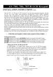
+
C10
VA3
VA4
+
D28
C13
+12V -V
VA7
D8
D13
R84 R81
R99
R80
ON A1
+
R33
+
VA8
-R11
K3
Q3
R53
D40
DIAL
R94
C21
D17
U17
1
LD1 R28
+
R34
C64
#
9
maximum, or use wireless remote device to Arm/Disarm System
0
*
6
type 12V – 7.2 AH
8
7
3
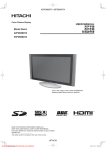
9 • Remote Arming: Use spring-return lock type; run wires of 20 meters
5
4
PHONES
TEL-LINE
RS-232 adapter
4 • Battery: Electronic Fuse protected. Recommended Battery: Sealed Lead Acid
2
1
To Aux. Power
YE OR
VA6
D2
R16
R12
U11
+ R93
C31
J2
R90
8 • EOL Resistors: To disable E.O.L. resistors, refer to programming sheet
AV-GAD
Yellow
U4
U7
U5
R72
U15
C69
C33
R71
++
R95
R13
AV-2004
7• Tel. Line: Dialing is applicable for DTMF and Pulse telephone systems
R82
C37
R48
Y1
C60
C32
R92
Q31
Q32
R97
R91
R89
using 2-2.5 m2 wire, as short length as possible, and no longer than 4 meters.
3 • Fuses: Fuses are automatic type. When overloaded wait 2-3 min. w/o load
-V
R9
U12
R36
C61
C68
U8
D32
ratings. For self contain bells program 3 in address 073
4
D26
U14
R60
R85
R96
F10
2 • Grounding: Connect Ground from the board to Cold Water pipe (ground),
3
U13
D25
C3
RF3 D18
D20
C23
U1
C18
C22
++
D33
1.25A
SIREN FUSE
6 • Sirens: Connect horn-type siren (speaker). If using Bell adhere to maximum
2
D24
R6
Q6
C12
Q4
C17
C15
D16
R42
R25
R7
R5
R8
R62
Q7
1
D23
RF4 D19
FA1
VA11
D14D21
D10D15
R44
Q5
R43
VA12
C19
R41
Cold water pipe
ground
Aux. Power
Remote
Key
+
D34
-
F1
+
D9 C16
Make sure main power is fused and not connected to an automatic switch
220V
AC
AC16V
+SIR
-SIR
TT2
+BATT-
5 • Keypad: Connect maximum of two AV-701 or four AV-702 keypads
Main
AV-GAD
Battery
Auxiliary Power Output
Regulated 13.8V. Observe
maximum current-0.8A, combined
keypad and Aux.
1 • Transformer: Connect step-down transformer to a non-switched main outlet
To prevent electrical
shock, disengage the
System and
disconnect the
telephone line before
servicing this unit.
WARNING:
AV-2004 and AV-2048 Wiring Diagram
WIRING DIAGRAM
Addendum: Technical Specifications AV-2004 and AV-2048
Operating Temperature
Relative Humidity
Input AC Power
Dynamic Inner Memory
Auxiliary Power Output
-10°C to 60°C
80% maximum
16V AC Step-Down Transformer 1.2A
EEprom
13.8 Volts +/- 5%, Regulated
Short & Overload circuit protection
Siren Output
Siren or Bell Selectable
Bell Mode: 13.6V DC - 0.5A
Siren: 8 Ohms, 15W
Dialer: Programmable 3 telephone numbers Pulse Dialing parameters programmable
& 1 Follow Me telephone number (4 phone DTMF: Touch Tone dialing
numbers).
Max. Telephone number length: 16 digits
Multi-format central-station communicator
and 4 pauses.
Remote Indications on Wire Terminal
Open Collector type output
200mA Max. @ 12V DC
Zone Loop Voltage
12V VDC or 6V with EOL resistor
Zone Loop Current
5 mA with End-Of-Line Resistor
Zone Maximum Wire Length
200 meters with 0.5-mm2 wires
EOL Zone Loop Resistor
2,200 Ohms, 0.25W, +/- 5%
AV-2048: 2,200 and 4,700 Ohms
Auxiliary Power (Max.)
13.6V DC 0.5A Combined AUX Power
and Keypad outputs.
Battery Charging Current (Max.)
550 mA, current limited
Battery Test: Indication at keypad or remote Performed at 0.5A load for 1 second.
indication via communicator
Low Battery indication below 9.5V
Tested upon Arming and every 60 minutes
during Armed and Disarmed
Standby Power Consumption at Disarmed
90 mA, +/- 10 %
mode, and Keypad display is Off
Maximum Remote Station (Keypads)
Three Keypads AV-701T or AV-701TI
Five Keypads AV-702
Remote Station Current Consumption
AV-701T: 27mA. AV-701TI: 36mA
Housing Dimensions
(H) 30, (D) 9, (W) 23 cm
System Housing
Standard: ABS plastic box
Option: Anodized, lockable metal box
Epoxy anti-static powder painted
Gross Shipping Weight
0.9 kg (ABS box, without transformer). 6
PCs per master box
Fuses: Electronic Fuse
Auxiliary Power: 1.2A
Sirens: 1.2A
Backup Battery Fuse: 2.5A
This product is subject to continual enhancement and therefore
specifications may be changed or altered without prior notice
27
AV-GAD LIMITED WARRANTY
Av-Gad Systems Ltd. (Av-Gad) warrants its products to be free from production defects in components,
materials used and labor for twelve months following the date of production. Av-Gad will within the
mentioned period, as its option, repair or replace any product failing to proper operation without charging
the purchaser.
This warranty shall not apply to any equipment, or any part thereof, which has
been repaired by others, installed not proper, used improper, abused, altered
damaged or subjected to forces of nature or on which the serial and data code
is altered or removed.
Av-Gad will not be responsible for any dismantling or reinstallation expenses.
In order to exercise the warranty, the product must be returned by the
purchaser, delivery and transportation costs will be prepaid and insured to AvGad.
After repair or replacement, Av-Gad assumes the cost of returning products
under warranty.
There are no warranties, expressed or implied, which extend beyond the
description of the face hereof.
There is no express or implied warranty of merchantability or a warranty of
fitness for particular purpose. Additionally, this warranty is in lieu of all other
obligations or liabilities on the part of Av-Gad.
Any action for breach of warranty, including but not limited to any implied
warranty of merchantability, must be brought within three months following
the end of the warranty period. In no case shall Av-Gad be liable to anyone for
any consequential or incidental damages for breach of this or any other
warranty, expressed or implied, even if the loss or damage is caused by the
seller’s own negligence or fault.
Av-Gad is not an insurer of either the property or safety of the user’s employees, family, or 3rd part and
limits its liability for any loss or damage including incidental or consequential damages to Av-Gad
original selling price of the product regardless of the cause of such a loss or damage.
Av-Gad hereby declares that service, technical support and spare parts will be supplied for 60 months
following the date of production. Price list for such services will be updated from time to time.
All rights reserved to Av-Gad Systems Ltd. December 2007. 2K4_EXP_3.06, Edition I. Item 4718_2004
28