1
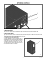
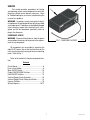
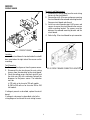
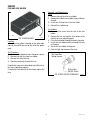
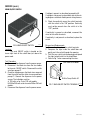
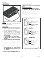
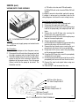
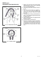
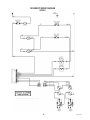
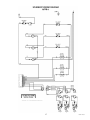
BUNN AF PR-2
®
AF PR-3
AFPR-3 VERSION DISCONTINUED
The information in this manual
is no longer current.
OPERATING & SERVICE MANUAL
BUNN-O-MATIC CORPORATION
POST OFFICE BOX 3227
SPRINGFIELD, ILLINOIS 62708-3227
PHONE: (217) 529-6601 FAX: (217) 529-6644
28791.0001B
1/00 ©1998 Bunn-O-Matic Corporation
INTRODUCTION
This equipment supplies a premixed liquid product to the hoppers on the CDS-2 or 3 dispensers. It is for indoor
use only on a sturdy counter or shelf.
WARRANTY
Bunn-O-Matic Corp. (“Bunn”) warrants the equipment manufactured by it to be commercially free from defects in material and workmanship existing at the time of manufacture and appearing within one year from the
date of installation. In addition:
1.) Bunn warrants electronic circuit and/or control boards to be commercially free from defects in material
and workmanship for two years from the date of installation.
2.) Bunn warrants the compressor on refrigeration equipment to be commercially free from defects in material and workmanship for two years from the date of installation.
3.) Bunn warrants that the grinding burrs on coffee grinding equipment will grind coffee to meet original
factory screen sieve analysis for three years from date of installation or for 30,000 pounds of coffee, whichever
comes first.
This warranty does not apply to any equipment, component or part that was not manufactured by Bunn or
that, in Bunn’s judgement, has been affected by misuse, neglect, alteration, improper installation or operation,
improper maintenance or repair, damage or casualty.
THE FOREGOING WARRANTY IS EXCLUSIVE AND IS IN LIEU OF ANY OTHER WARRANTY, WRITTEN OR
ORAL, EXPRESS OR IMPLIED, INCLUDING, BUT NOT LIMITED TO, ANY IMPLIED WARRANTY OF EITHER
MERCHANTABILITY OR FITNESS FOR A PARTICULAR PURPOSE. The agents, dealers or employees of Bunn
are not authorized to make modifications to this warranty or to make additional warranties that are binding on
Bunn. Accordingly, statements by such individuals, whether oral or written, do not constitute warranties and
should not be relied upon.
The Buyer shall give Bunn prompt notice of any claim to be made under this warranty by telephone at (217)
529-6601 or by writing to Post Office Box 3227, Springfield, Illinois, 62708-3227. If requested by Bunn, the
Buyer shall ship the defective equipment prepaid to an authorized Bunn service location. If Bunn determines, in
its sole discretion, that the equipment does not conform to the warranty, Bunn shall repair the equipment with no
charge for parts during the warranty period and no charge for labor by a Bunn Authorized Service Representative
during the warranty period. If Bunn determines that repair is not feasible, Bunn shall, at its sole option, replace
the equipment or refund the purchase price for the equipment.
THE BUYER’S REMEDY AGAINST BUNN FOR THE BREACH OF ANY OBLIGATION ARISING OUT OF THE
SALE OF THIS EQUIPMENT, WHETHER DERIVED FROM WARRANTY OR OTHERWISE, SHALL BE LIMITED, AS
SPECIFIED HEREIN, TO REPAIR OR, AT BUNN’S SOLE OPTION, REPLACEMENT OR REFUND.
In no event shall Bunn be liable for any other damage or loss, including, but not limited to, lost profits, lost
sales, loss of use of equipment, claims of Buyer’s customers, cost of capital, cost of down time, cost of substitute
equipment, facilities or services, or any other special, incidental or consequential damages.
USER NOTICES
Carefully read and follow all notices on the equipment and in this manual. They were written for your protection.
All notices are to be kept in good condition. Replace any unreadable or damaged labels.
00656.0000
00986.0002
2
28791.1 011500
INITIAL SET-UP
NOTE: This refill unit should not be used to initially fill the hopper. Running the motor for extended periods will
trip the thermal switch. The thermal switch will reset, but requires up to 30 minutes of cooling time.
NOTE: Hoses, clamps and product container connectors are not supplied. Fittings and labels are supplied. Make
hose assemblies as required.
1. Assemble hoppers with probe housing assemblies to CDS-2, CDS-3 or modify existing hoppers using template provided.
2. Make sure probe housing assembly is pushed down into slots on back of hoppers.
3. Install cable assembly to the lower right front of the auto refill box and the probe housing assemblies on the
hoppers. The connectors on the cable pushes in and cap rotates 1/4 turn to lock into position.
4. Run output tubes from auto refill box to the quick disconnects in the hoppers.
NOTE: Make sure numbers on the labels match up. Cable#1 with Hose#1, Cable#2 with Hose#2...ect.
5. Connect one end of input hoses to the auto refill box and the other end to the product container. Product
container connectors (BIB) are not supplied. Install your own interface.
NOTE: Make sure all connections are made before connecting the auto refill box to the power source.
6. Each product container has an ON/OFF refill switch located on the front of the auto refill box. A second switch
for each hopper is at the probe housing assembly. These are 3 position switches, high level, low level and a
center “OFF” position.
7. Place the main ON/OFF switch and ON/OFF refill switches in the “OFF” position.
8. Make sure all hoses are connected. Connect the dispenser to the power source and place the main ON/OFF
switch in the “ON” position.
9. Place one of the ON/OFF refill switches in the “ON” position, after a four second delay product will begin to
flow through the hoses into the hopper. Be sure the switch selected is filling the correct hopper, if not, check
the labels. See NOTE in step #4.
10. To test refill circuit short out probes on one of the hoppers with a screwdriver, that hopper should shut off,
remove the screwdriver and the hopper will start to fill again after a four second delay. If hopper does not
start to fill, check labels, refer to NOTE in step #4.
ELECTRICAL REQUIREMENTS
CAUTION - The dispenser must be disconnected from the power source until specified in Initial Set-Up.
The 120 volt version of this dispenser has an attached cordset and requires 2-wire, grounded service rated 120
volts ac, 15 amp, single phase, 60 Hz. The mating connector must be a NEMA 5-15R.
The 200 volt or 240 volt versions require 2 wire, grounded service rated 200 volts ac or 240 volts ac, single
phase, 50 Hz.
(Refer to the dispenser’s data plate for exact voltage requirement.)
Electrical Hook-Up
CAUTION – Improper electrical installation will damage electronic components.
1. An electrician must provide electrical service as specified.
2. Using a voltmeter, check the voltage and color coding of each conductor at the electrical source.
3. Connect the dispenser to the power source.
3
28791.1 011500
CLEANING
RECOMMENDED WEEKLY CLEANING:
This should be done in conjunction with the recommended weekly cleaning of your CDS-2 or CDS-3 machine. The
CDS Hoppers must be empty before starting.
1. Prepare a 1 gallon cleaning solution consisting of 1 gallon of hot water and a sanitizing cleaner which contains
3-5% chlorine based sanitizer. Mix per manufacturers instructions
2. Remove connectors from each concentrate container and place them directly into the cleaning solution.
3. Energize each refill station and allow the cleaning solution to pump through the system into the hoppers. The
cleaning procedure should remove the color stains from the tubing. If not, prepare another gallon of cleaning
solution and repeat.
4. After the cleaning solution has been pumped into the hoppers, rinse the cleaning solution container with hot
water.
5. Fill the cleaning solution container with hot water. Energize each refill station and rinse thoroughly. The amount
of clean hot rinse water should equal the amount of cleaning solution pumped through the system.
6. Empty the hoppers of your CDS machine and follow the recommended cleaning instructions.
NOTE: The hoses should be checked monthly for deterioration, cracks and possible discoloration from some
concentrates. Replace the tubing when necessary.
TROUBLESHOOTING
A troubleshooting guide is provided to suggest probable causes and remedies for the most likely problems
encountered. If the problem remains after exhausting the troubleshooting steps, contact the Bunn-O-Matic
Technical Service Department.
•
•
•
•
•
•
•
Inspection, testing, and repair of electrical equipment should be performed only by qualified service personnel.
All electronic components have 120 volt ac and low voltage dc potential on their terminals. Shorting of
terminals or the application of external voltages may result in board failure.
Intermittent operation of electronic circuit boards is unlikely. Board failure will normally be permanent. If
an intermittent condition is encountered, the cause will likely be a switch contact or a loose connection at a
terminal or crimp.
Solenoid removal requires interrupting the water supply to the valve. Damage may result if solenoids are
energized for more than ten minutes without a supply of water.
The use of two wrenches is recommended whenever plumbing fittings are tightened or loosened. This will
help to avoid twists and kinks in the tubing.
Make certain that all plumbing connections are sealed and electrical connections tight and isolated.
Keep away from combustibles.
WARNING – •
•
•
•
Exercise extreme caution when servicing electrical equipment.
Unplug the dispenser when servicing, except when electrical tests are specified.
Follow recommended service procedures
Replace all protective shields or safety notices
4
28791.1 011500
OPERATING CONTROLS
B
A
P2052
A. MAIN POWER ON/OFF
The main power ON/OFF switch is located on the right of the front panel just above the power cord.
B. REFILL CIRCUIT ON/OFF
The refill circuit ON/OFF switches are located on the right of the front panel just above the main power switch.
These allow each circuit to operate independently of the other.
C. PROBE CONTROL BOX LOW/OFF/HIGH
On models equipped with a dual level probe, there is a
LOW/OFF/HIGH switch located at the probe control box
on the hopper. The “OFF” position allows the operator
to disable the probe for that hopper only. THE “LOW”
C
and “HIGH” positions allow the operator to select the
level of product desired for that hopper.
P1951
5
28791.1 011500
TROUBLESHOOTING (cont.)
PROBLEM
PROBABLE CAUSE
REMEDY
Product will not dispense
1. Empty product container
Replace or refill
2. No power or incorrect voltage to (A1) Check the outlet for 120 volts
the dispenser
on two wire 120 volt dispenser.
(A2) Check the outlet for 200 volts
or 240 volts ac for two wire 200 volt
or 240 volt dispensers.
(B) Check circuit breakers or fuses.
Motor thermal cutout (motor stops
running)
3. Signal cable unplugged
Signal cable must be plugged in.
4. Hopper is full
Product must not be touching probes
to fill.
5. Fuse and fuse holder
Refer to Service - Fuse and Fuse
Holder for test procedures. See
page 8
6. Main ON/OFF switch
Refer to Service - Main ON/OFF
Switch for testing procedure. See
page 9
7. Probe box LOW/OFF/HIGH switches
Refer to Service - Probe System.
See page 10
8. Circuit board
Refer to Service - Circuit Board for
testing procedures. See page 7
9. Vacuum switches
Refer to Service - Vacuum Switches
for testing procedures. See page 14
10. Vacuum/Supply pump
Refer to Service - Vacuum/ Supply
Pump for testing procedures. See
page 12
1. Motor over heats
The thermal switch will reset, but
requires up to 30 minutes of cooling
time. See NOTE below.
NOTE: This refill unit should not be used to initially fill the hopper. Running the motor for extended periods will
trip the thermal switch. The thermal switch will reset, but requires up to 30 minutes of cooling time.
6
28791.1 011500
SERVICE
This section provides procedures for testing
and replacing various major components used in this
dispenser should service become necessary. Refer
to Troubleshooting for assistance in determining the
cause of any problem.
WARNING - Inspection, testing, and repair of electrical equipment should be performed only by qualified
service personnel. The dispenser should be unplugged
when servicing, except when electrical tests are required and the test procedure specifically states to
plug-in the dispenser.
COMPONENT ACCESS
WARNING - Disconnect the dispenser from the power
source before the removal of any panel or the replacement of any component.
FIG. 1 COMPONENT ACCESS
P1561
All components are accessible by removing the
eight #8-32 screws (five on the front and three on the
rear) securing the main housing to the main mounting
panel. Refer to Fig. 1
Refer to the contents listing for component location.
Contents
Circuit Board............................................................ 8
Fuse & Fuse Holder.................................................. 9
Main ON/OFF Switch.............................................. 10
Probe LOW/OFF/HIGH Switches............................. 11
Refill ON/OFF Switches......................................... 12
Vacuum/Supply Pump Assembly........................... 13
Vacuum/Supply Pump Tubing Installation............. 14
Vacuum Switches.................................................. 15
Wiring Diagrams............................................... 16,17
7
28791.1 011500
SERVICE
CIRCUIT BOARD
FFO
Removal and Replacement:
1. Disconnect the ten pin plug from the main wiring
harness to the circuit board.
2. Remove the six #4-40 screws and spacers securing
the circuit board to the solenoid mounting bracket.
Remove circuit board and discard.
3. Install new circuit board using #4-40 screws and
spacers to secure the circuit board to the vacuum
switch mounting bracket. The spacers must be
between the solenoid mounting bracket and the
circuit board.
4. Refer to Fig. 3 for circuit board ten pin connector.
NO
FFO
NO
FFO
NO
FIG. 2 CIRCUIT BOARD
P1556
Location:
The circuit board is located inside the autofill
box, mounted on the right side of the vacuum switch
mounting.
Test Procedure:
1. Disconnect the dispenser from the power source.
2. Disconnect the ten pin plug on the main wiring
harness from the connector on the circuit board.
3. Check the voltage across the black wire(#3) and
the white wire (#6) with a voltmeter. Connect the
dispenser to the power source. The indication
must be:
a) 120 volts ac for two wire 120 volt models.
b) 200 to 240 volts ac for two wire 200 or 240
volt models.
P1528
FIG. 3 CIRCUIT BOARD CONNECTOR LOCATION
If voltage is present as described, replace the circuit
board.
If voltage is not present as described, refer to the
wiring diagrams and check the main wiring harness.
8
28791.1 011500
SERVICE
FUSE AND FUSE HOLDER
Removal and Replacement:
Fuse:
1. Remove the cap from the fuse holder.
2. Remove fuse from the fuse holder, inspect, if blown
discard.
3. Install new 10 amp fuse in the fuse holder.
4. Reinstall fuse holder cap.
FIG. 4 FUSE HOLDER
Fuse Holder:
1. Disconnect the wires from the rear of the fuse
holder.
2. Remove the nut securing the fuse holder to the
front of the main mounting panel.
3. Push the fuse holder through the hole in the panel.
4. Install new fuse holder and fuse through the hole
in the panel.
5. Secure the fuse holder to the panel.
6. Refer to Fig 5 and reconnect the wires.
P1561
Location:
The fuse holder is located on the lower right
front of the autofill box just to the left of the power
cord.
Test Procedure:
1. Disconnect the dispenser from the power source.
2. Remove cap and fuse from fuse holder.
3. Remove fuse from the cap.
4. Check for continuity through the fuse.
BLK from Main
Wiring Harness
If continuity is present as described, reinstall the fuse,
the fuse is operating properly.
If continuity is not present as described, replace the
fuse.
BLK to Main
ON/OFF Switch
FIG. 5 FUSE HOLDER TERMINALS
9
P1331
28791.1 011500
SERVICE (cont.)
MAIN ON/OFF SWITCH
If voltage is present as described, proceed to #5.
If voltage is not present as described, refer to the wiring diagrams and check the dispenser wiring harness.
5. Check for continuity across the switch terminals
with the switch in the “ON” position. Continuity
must not be present when the switch is in the
“OFF” position.
If continuity is present as described, reconnect the
wires to the switch terminals.
If continuity is not present as described, replace the
switch.
FIG. 6 MAIN ON/OFF SWITCH
P1561
Removal and Replacement::
1. Remove the wires from the switch terminals.
2. Compress the clips inside the autofill box and
gently push the switch through the opening
3. Push the new switch into the opening and spread
the clips to hold switch in the autofill box.
4. Refer to Fig 7 when reconnecting the wires.
Location:
The main ON/OFF switch is located on the
lower right front of the autofill box just above the
power cord.
Test Procedure:
1. Disconnect the dispenser from the power source.
2. Disconnect the black wire from the fuse holder
to the main ON/OFF switch. Disconnect the white
wire from pump #1.
3. Check for voltage across the black wires removed
from the switch and the white wire removed from
pump #1. Connect the dispenser to the power
source. The indication must be:
a) 120 volts ac for 2 wire 120 volt models.
b) 200 to 240 volts ac for two wire 200 or 240 volt
models.
4. Disconnect the dispenser from the power source.
BLK from Fuse Holder
BLK to Pump Switch #2
FIG. 7 MAIN ON/OFF SWITCH TERMINALS
10
P1522
28791.1 011500
SERVICE (cont.)
PROBE SYSTEM
Probe Boxes:
1. Disconnect the signal cable from the probe boxes.
2. Remove probe box from CDS hopper.
3. Place the switch on the probe box in the “HIGH”
position.
4. Check the resistance across the box cable pins,
see Fig. 8B.
AFPR-2 & 3
FIG. 8B PROBE BOX CABLE PINS
FIG. 8 PROBE SWITCHES
P1539
5. With the probe box switch in the “LOW” position
check the ohms across the pins, refer to Fig. 8B.
6. If readings match the values indicated the probe
system electrically is functioning properly.
P1523
Location
The probe switches are located on the rear of
each hopper, mounted in the probe housing cover.
Switch Removal and Replacement:
1. Remove the #6 thread cutting screw securing the
probe housing cover to the probe housing.
2. Remove the wires from the switch terminals.
3. Compress the clips inside the probe box and gently
push the switch through the opening
4. Push the new switch into the opening and spread
the clips to hold switch in the autofill box.
5. Refer to Fig 9 when reconnecting the wires.
Test Procedure
Probe System
1. Disconnect the dispenser from the power source.
2. With the probe boxes connected to the signal
cable, remove connector from refill box.
3. Place the switch on the probe box in the “HIGH”
position.
4. Check resistance across pins as shown in Fig 8A.
5. With the probe box switch in “LOW” position
check the ohms across the signal cable pins, see
Fig. 8A.
6. If readings match values indicated the probe
system electrically is functioning properly. If not
check the probe boxes.
BLU (HIGH) fromProbe
Box Cable
GRN (OFF) from Probe
Box Cable
TAN (LOW) from Probe Box
Cable
FIG. 9 PROBE LOW/OFF/HIGH SWITCH TER-P1540
MINALS
AFPR-2
AFPR-3
FIG. 8A SIGNAL CABLE PINS
P1538
11
28791.1 011500
SERVICE (cont.)
wires to the switch terminals.
If continuity is not present as described, replace the
switch.
Removal and Replacement:
1. Remove the wires from the switch terminals.
2. Compress the clips inside the autofill box and
gently push the switch through the opening in the
front of autofill box.
3. Push the new switch into the opening and spread
the clips to hold switch in the autofill box.
4. Refer to Fig 13 when reconnecting the wires.
REFILL SWITCHES
#1 AFPR-2 & 3
FIG. 12 REFILL SWITCHES
P1561
RED/BLK from Test/
Operate Switch
RED/BLK to Vacuum
Switch #1
Location:
The refill switches are located on the upper
right front of the autofill box.
Test Procedures:
1. Disconnect the dispenser from the power source.
2. Disconnect the two white/red, brown/black or red/
black wires from the switch terminals.
3. Check for voltage across the white/red, brown/
black or red black wires from the test/operate
switch and the white wire on solenoid #2 or #3.
Connect the dispenser to the power source. The
indication must be:
a) 120 volts ac for two wire 120 volt models
b) 200 to 240 volts ac for two wire 200 or 240
volt models.
4. Disconnect the dispenser from the power source.
#2 AFPR-2 & 3
BRN/BLK from Test/
Operate Switch
BRN/BLK to Vacuum
Switch #2
#3 AFPR-3 ONLY
WHI/RED from Test/
Operate Switch
WHI/RED to Vacuum
Switch #3
If voltage is present as described, proceed to #5.
If voltage is not present as described, refer to the wiring diagrams and check the dispenser wiring harness.
5. Check for continuity across the switch terminals
with the switch in the “ON” position. Continuity
must not be present when the switch is in the
“OFF” position.
FIG. 13 REFILL SWITCH TERMINALS
P1522
If continuity is present as described, reconnect the
12
28791.1 011500
SERVICE (cont.)
a) 120 volts ac for two wire 120 volt models.
b) 200 to 240 volts ac for two wire 200 or 240 volt
models.
If voltage is present as described, replace the pump.
If voltage is not present as described, refer to the
wiring diagrams and check the main wiring harness.
VACUUM/SUPPLY PUMP ASSEMBLY
Pump Removal and Replacement:
1. Disconnect the wires from the pump leads.
2. Disconnect the input and output tubes.
3. Remove the four thumb screws securing the pump
head to the pump body, discard pump head with
tubes.
4. Remove the two #8-32 keps nuts securing the
pump to the main mounting panel.
5. Remove the two #6-32 screws securing the pump
body to the mounting bracket.
6. Remove pump body and discard.
7. Install new pump assembly on the pump mounting
bracket and secure with two #6-32 screws.
8. Remove the four thumb screws securing the new
pump head with hoses to the new pump body.
9. Using two #6-32 screws mount the pump body
on the pump mounting bracket.
10. Using two #8-32 keps nuts mount the pump body
and bracket to main panel.
11. Install new pump head with hoses to the rear of the
pump body and secure with four thumb screws.
12. Connect the input and output tubes using new
hose clamps.
13. Refer to Fig 17 and reconnect the wires.
P1560
FIG. 16 VACUUM/SUPPLY PUMP ASSEMBLY
Location:
The vacuum/supply pumps are located inside
the autofill box.
Test Procedure:
1. Disconnect the dispenser from the power source.
2. Disconnect the white wire from the pump lead and
the yellow, orange or red wire from the other lead.
3. Check the voltage across the white wire and yellow,
orange or red wire with a voltmeter. Connect the
dispenser to the power source. Push the pump
(flavor) switch for the pump to be tested. The
indication must be :
WHI from Main Harness
YEL from Pump Switch #1
WHI from Pump #1
ORN from Pump Switch #2
WHI from Pump #2
RED from Pump Switch #3
FIG. 17 VACUUM/SUPPLY PUMP TERMINALS
13
P1526
28791.1 011500
SERVICE (cont.)
VACUUM/SUPPLY PUMP TUBE INSTALLATION
1. Separate the pump head from the pump body.
Hold pump head as shown in Fig. 18, with roller
in the 2, 6 10 o’clock positions.
2. Wrap tubing around rollers and hold as shown in
Fig. 18.
3. Insert the slot of the tubing key (supplied), as
shown in Fig. 18 on the rotor so the bottom edge
of the key is pressing the tubing into the pump
head cavity.
4. Push down and turn the key counterclockwise to
guide the tubing deep into the pump head cavity
as shown in Fig. 19.
5. Hold the tubing and rotor in the pump head and
remove key carefully.
6. Place pump body on the rotor shaft.
7. Squeeze the pump body and pump head together
simultaneously until pump body and pump head
are touching on all sides. Be careful not to pinch
the tubing between the pump body and the pump
head.
ROLLERS
PUMP
HEAD
TUBING
KEY
EXIT
PORT
ENTRY
PORT
FIG. 18 TUBING START POSITION
P1542
ROTOR
ROTOR
SHAFT
FIG. 19 TUBING LOADED
P1541
14
28791.1 011500
SERVICE (cont.)
Removal and Replacement:
1. Disconnect dispenser from the power source.
2. Remove the four thumb screws securing the right
side pump head to the right side pump.
3. Disconnect the input tube from the pump to vacuum
switch to be removed.
4. Remove the two #8-32 keps nuts securing the
pump and bracket to main panel.
5. Disconnect the yellow and white wires from the
pump.
6. Remove pump and bracket as an assembly.
7. Disconnect the input tubes from the vacuum switch
to be replaced.
8. Disconnect the wires on the vacuum switch to be
removed.
9. Remove the two #4-40 screws securing the vacuum
switch to the bracket. Remove and discard switch.
10. Using two #4-40 screws secure the new vacuum
switch to the bracket.
11. Refer to Fig 17 and reconnect the wires.
12. Install pump and bracket over the two studs on the
bottom of main panel and secure with two #8-32
keps nuts.
13. Install the pump head with tubes on the back of
the pump and secure with four thumb screws.
14. Reconnect the yellow and white wires to the pump.
15. Connect the input hose from the pump to the new
vacuum switch.
VACUUM SWITCHES
FIG. 16 VACUUM SWITCHES
P1505
Location:
The vacuum switches are located inside autofill
box, mounted on the left side of the mounting bracket.
Test Procedure:
1. Disconnect the dispenser from the power source.
2. Disconnect flavor input lines.
3. Disconnect white/red, red/black or the brown/black
wires on the vacuum switch.
4. Check for continuity across the switch leads.
If continuity is present as described, the vacuum switch
is operating properly.
If continuity is not present as described, without a
vacuum generated by a empty product concentrate,
replace the vacuum switch.
WHI/RED from Refill ON/OFF Switch #3
WHI/RED to Circuit Board J4-2
RED/BLK from Refill ON/OFF Switch #1
RED/BLK to Circuit Board J4-5
#3
#1
BRN/BLK from Refill ON/OFF Switch #2
BRN/BLK to Circuit Board J4-4
#2
FIG. 17 VACUUM SWITCH TERMINALS
15
P1527
28791.1 011500
16
28791.1 011500
17
28791.1 011500