1
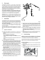
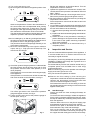
supply at the inlet cock.
Open the taps to release any remaining water
pressure and drain the appliance.
c) Remove the water discharge pipe.
d) Undo the union connection on the water isolating
cock.
e) Pull out the retaining clips at the inlet and outlet
connections on the water control body, and spring
out the copper inlet and outlet pipes from the control
body. Take care not to damage the two ‘O’ ring seals.
f) Pass a screwdriver through the hole in the centre of
the lower edge of the fascia panel and slacken the
first of the two retaining screws. The second retaining
screw is located at 90 degrees on the right and is
accessed from the side.
g) With both screws slackened the water control
assembly can be withdrawn downwards away from
the gas valve body.
h) Replace in reverse order.
10.7 Gas Valve
a) Remove the burner as described in section 9.4 above
b) Remove the water control assembly as described in
10.6 above.
c) Undo the gas inlet union at the rear of the gas valve
d) Access the two gas valve retaining screws from the
left hand side and remove.
e) Withdraw the gas valve, complete with slider
controls, from the appliance.
f) Remove the Piezo igniter.
g) Remove the control fascia by taking out the four fixing
screws and lifting clear complete with slider knob.
h) Prise out the slider bar and remove the two screws
retaining the control frame and lift clear.
i) Assemble the Piezo igniter, slider bar, control fascia
and pilot pipe to the new gas valve.
j) Re-assemble the gas valve, burner and water control
assembly in reverse order.
10.8 Final Inspection
Turn on the gas supply at the main gas service cock
and check for gas soundness in accordance with the
current edition of BS 6891 while the appliance is
running.
Re-commission the appliance as described in section
8.
9