1
PowerEdge T710 Technical Guidebook
DELL
TM
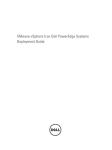
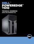
POWEREDGE T710
TM
TECHNICAL GUIDEBOOK
INSIDE THE POWEREDGE T710
Dell
PowerEdge T710 Technical Guidebook
Table of Contents
1
Product Comparison ......................................................................................................................... 1
2
1.1
Overview ................................................................................................................................... 1
New Technologies............................................................................................................................. 2
2.1
Overview/Description ................................................................................................................ 2
2.2
Detailed Information .................................................................................................................. 2
2.2.1
Intel Xeon 5500 Series Processors ...................................................................................2
2.2.2
Intel 5520 Chipset .............................................................................................................3
2.2.3
PCIe Generation 2.............................................................................................................3
2.2.4
DDR3 Memory Technology ...............................................................................................3
2.2.5
16-Drive Active Backplane ................................................................................................3
2.2.6
Next Generation Broadcom 5709C LOMs ......................................................................... 4
2.2.7
Next generation Dell Embedded Server Management ...................................................... 4
3
System Overview .............................................................................................................................. 4
3.1
Overview/Description ................................................................................................................ 4
3.2
T710 Product Features Summary ............................................................................................. 5
4
Mechanical ........................................................................................................................................ 6
4.1
Chassis Description .................................................................................................................. 6
4.2
Dimensions and Weight ............................................................................................................ 6
4.3
Front Panel View and Features ................................................................................................. 7
4.4
Back Panel View and Features ................................................................................................. 7
4.5
Power Supply Indicators ........................................................................................................... 8
4.6
Side Views and Features .......................................................................................................... 8
4.7
Internal Chassis Views .............................................................................................................. 9
4.8
Rails and Cable Management ................................................................................................... 9
4.9
Rack View ............................................................................................................................... 10
4.10 Fans ........................................................................................................................................ 10
4.11 Control Panel/LCD .................................................................................................................. 11
4.11.1
Cover Latch .....................................................................................................................12
4.11.2
Bezel ...............................................................................................................................12
4.11.3
Hard Drive .......................................................................................................................13
4.11.4
Trusted Platform Management (TPM) ............................................................................. 13
4.11.5
Power-Off Security ..........................................................................................................13
4.11.6
Intrusion Alert ..................................................................................................................13
4.11.7
Secure Mode ...................................................................................................................13
4.12 Persistent Storage................................................................................................................... 14
4.12.1
Managed Persistent Storage ...........................................................................................14
4.12.2
SD Module (Unmanaged Internal Persistent Storage) .................................................... 15
4.13 USB Key (Unmanaged Internal Persistent Storage) ............................................................... 16
4.14 Battery ..................................................................................................................................... 16
4.15 Field Replaceable Units (FRU) ............................................................................................... 16
5
Electrical.......................................................................................................................................... 16
5.1
Clock Circuitry ......................................................................................................................... 16
5.2
Volatility ................................................................................................................................... 16
6
Power, Thermal, and Acoustic ........................................................................................................ 16
6.1
6.2
6.3
6.4
Dell
Power Supplies ....................................................................................................................... 16
Power Supply Specifications ................................................................................................... 17
Power Efficiency...................................................................................................................... 18
Environmental Specifications .................................................................................................. 19
PowerEdge T710 Technical Guidebook
6.6
Maximum Input Amps ............................................................................................................. 20
6.7
EnergySmart Enablement ....................................................................................................... 20
6.8
Energy Star Compliance ......................................................................................................... 20
6.9
Acoustics ................................................................................................................................. 20
7
Block Diagram ................................................................................................................................. 22
8
Processors ...................................................................................................................................... 22
8.1
Overview ................................................................................................................................. 22
8.2
Features .................................................................................................................................. 23
8.3
Supported Processors............................................................................................................. 23
8.4
Processor Configurations ........................................................................................................ 24
8.5
Additional Processor Information ............................................................................................ 24
9
Memory ........................................................................................................................................... 24
9.1
Overview ................................................................................................................................. 24
9.2
DIMMs Supported ................................................................................................................... 24
9.3
Memory Population Scenarios ................................................................................................ 24
9.4
Slots/Risers ............................................................................................................................. 25
9.5
Speed/Memory Features ......................................................................................................... 25
9.6
Memory Population ................................................................................................................. 26
9.7
Memory Speed Limitations ...................................................................................................... 26
9.8
Mirroring .................................................................................................................................. 27
10 Chipset ............................................................................................................................................ 27
10.1 Overview ................................................................................................................................. 27
10.2 Intel 5500 Chipset Dual I/O Hub (IOH) .................................................................................... 27
10.3 Intel Quickpath Architecture .................................................................................................... 28
10.4 PCI Express Generation 2 ...................................................................................................... 28
10.5 Intel Direct Media Interface (DMI) ........................................................................................... 28
10.6 Super I/O Controller ................................................................................................................ 29
11 BIOS................................................................................................................................................ 29
11.1 Overview ................................................................................................................................. 29
11.2 Supported ACPI States ........................................................................................................... 29
12 Embedded NICs/LAN on Motherboard (LOM) ................................................................................ 29
13
12.1 Overview ................................................................................................................................. 29
I/O Slots .......................................................................................................................................... 30
13.1 Overview ................................................................................................................................. 30
13.2 X16 Express Card Specifications ............................................................................................ 30
13.3 Available PCIe Cards .............................................................................................................. 31
13.4 Boot Order............................................................................................................................... 32
14 Storage............................................................................................................................................ 32
14.1 Overview ................................................................................................................................. 32
14.2 3.5” X8 HDD Backplane .......................................................................................................... 33
14.3 2.5” X16 HDD Backplane ........................................................................................................ 33
14.4 Storage Card Support Matrix .................................................................................................. 33
14.5 Available Drives ...................................................................................................................... 34
14.6 RAID Configurations ............................................................................................................... 35
14.7 Internal Storage Controllers .................................................................................................... 42
14.8 LED Indicators......................................................................................................................... 42
14.9 Optical Drives .......................................................................................................................... 42
14.10 Tape Drives ............................................................................................................................. 42
15 Video ............................................................................................................................................... 42
Dell
PowerEdge T710 Technical Guidebook
16
15.1 Overview ................................................................................................................................. 42
Audio ............................................................................................................................................... 43
17
Rack Information ............................................................................................................................. 43
17.1 Overview ................................................................................................................................. 43
17.2 Cable Management Arm (CMA) .............................................................................................. 43
17.3 Rack Configuration.................................................................................................................. 43
17.4 Rails ........................................................................................................................................ 44
18 Operating Systems.......................................................................................................................... 45
18.1 Overview ................................................................................................................................. 45
18.2 Operating Systems Supported ................................................................................................ 45
19 Virtualization.................................................................................................................................... 46
19.1 Overview ................................................................................................................................. 46
19.2 Virtualization Options Supported ............................................................................................. 46
20 Systems Management .................................................................................................................... 47
20.1 Overview/Description .............................................................................................................. 47
20.2 Server Management ................................................................................................................ 47
20.3 Embedded Server Management ............................................................................................. 48
20.4 Lifecycle Controller and Unified Server Configurator .............................................................. 48
20.5 Optional iDRAC Express ......................................................................................................... 49
20.6 iDRAC6 Enterprise .................................................................................................................. 49
21 Peripherals ...................................................................................................................................... 51
21.1 USB peripherals ...................................................................................................................... 51
21.2 External Storage ..................................................................................................................... 51
22 Packaging Options .......................................................................................................................... 51
Dell
PowerEdge T710 Technical Guidebook
1
Product Comparison
1.1
Overview
The PowerEdge T710 is the flagship of the Dell tower servers positioned above the PowerEdge T610
and replacing the PowerEdge 2900III. Table 1 shows a comparison between these versions.
Table 1.
Feature/Spec
Comparison of T710 to PE2900-III and T610
PE2900-III (predecessor)
®
T710
T610
®
Processor
Quad-Core Intel Xeon
Processor 5400 Series,
Intel Xeon 5200 Series
Intel Xeon 5500 Series
Intel Xeon 5500 Series
Front Side Bus
1066/1333 MHz
QPI 4.8 – 6.4 GT/s
QPI 4.8 – 6.4 GT/s
# Processors
1 or 2
1 or 2
1 or 2
# Cores
2 or 4 per proc
2 or 4 per proc
2 or 4 per proc
L2/L3 Cache
2 X 3MB or 2 X 6MB
shared L2
256K L2 per core/4MB or
8MB shared L3
256K L2 per core/4MB or
8MB shared L3
Chipset
Intel 5000X chipset
Intel 5520 chipset
Intel 5520 chipset
DIMMs
12
18
12
Min/Max RAM
1GB/48GB
1GB/144GB
1GB/96GB
HD Bays
8 or 10 X 3.5”
8 X 3.5” or 16 X 2.5”
8 X 3.5” or 2.5”
HD Types
SAS, SATA
SSD, SAS, SATA
SSD, SAS, SATA
Ext Drive Bay(s)
2 X HH Perhiperal Bays
2 X HH Perhiperal Bays
2 X HH Perhiperal Bays
Int. HD Controller
None
None
None
Opt. HD Controller
Perc 5/i, Perc 6/i, SAS
6/iR, SAS 5/i
Perc 6/i, SAS 6/iR
Perc 6/i, SAS 6/iR
Availability
Hot Swap HDD, Hot Swap
Redundant Fans, Hot
Swap Redundant PS
Hot Swap HDD, Hot Swap
Redundant Fans, Hot
Swap Redundant PS
Hot Swap HDD, Optional
Hot Swap Redundant
Fans, Hot Swap
Redundant PS
Server Mgt.
BMC, Optional DRAC5
iDRAC6 Express, Optional
iDRAC6 Enterprise,
Optional VFlash
iDRAC6 Express, Optional
iDRAC6 Enterprise,
Optional VFlash
I/O Slots
6 + Storage Controller
Slot
6 + Storage Controller
Slot
5 + Storage Controller
Slot
RAID
0, 1, 5, 6, 10
See RAID Configurations
0, 1, 5, 6, 10
NIC/LOM
2 X TOE/iSCSI
4 X TOE/iSCSI
2 X TOE/iSCSI
USB
2 Front, 4 Rear, 1 Internal
2 Front, 6 Rear, 1 Internal
2 Front, 6 Rear, 1 Internal
Power Supplies
930 W Redundant
1100 W Redundant
598 W Redundant
Fans
Hot plug Redundant
Hot plug Redundant
Cabled, Optional Hot plug
Redundant
Chassis
5U Rackable Tower
5U Rackable Tower
5U Rackable Tower
1
DELL
PowerEdge T710 Technical Guidebook
Feature/Spec
PE2900-III (predecessor)
T710
T610
Unmanaged Internal
Storage
Internal USB key
SD card for virtualization
solutions
SD card for virtualization
solutions
2
New Technologies
2.1
Overview/Description
The T710 utilizes the following new technologies common to other Dell 11G servers:
•
•
•
•
•
•
•
2.2
Intel Xeon 5520 Series processors
o New architecture with memory controller within each processor
o Dual and quad core
o Intel turbo mode allows increased processor speed
o Hyperthreading technology
o Quick Path Interconnect
Intel 5520 chipset
o Dual IOH for maximum I/O capability
PCIe Generation 2
DDR3 memory technology
16-drive active backplane with expander
Next generation Broadcom 5709C LOMs
Next generation Dell embedded server management
o iDRAC express with Lifecycle Controller and Unified Server Configurator
o Optional iDRAC enterprise
o Optional v-flash
Detailed Information
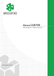
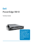
2.2.1 Intel Xeon 5500 Series Processors
Intel Xeon 5500 series processors are the latest generation Intel processors for two-socket servers.
They are based on a new 45nm die technology and utilize integrated memory controllers on the
processor itself rather than a separate memory controller. QuickPath interconnect technology, the
speed of which varies with the processor model, replaces the familiar front-side-bus.
2
DELL
PowerEdge T710 Technical Guidebook
QPI up to 25.6 GB/sec bandwidth per link
Intel Xeon
5500
Intel Xeon
5500
QPI
DDR3 Memory
Up to 18 slots
PCI Express
Gen 2
Figure 1.
Intel Xeon 5500 Series Processors
•
•
•
Intel Hyper-Threading Technology: enables more software threads to be running simultaneously
Intel Intelligent Power Technologies: scales server power consumption to performance needs
Intel Turbo Boost Technology: boosts frequency for active cores by up to 400 MHz for during
peak demand periods
See Section 8 “Processors” for more detail.
2.2.2 Intel 5520 Chipset
The Intel 5520 chipset is the companion to the new Intel Xeon 5500 series processor. It supports the
QuickPath interconnect technology and provides PCI Express Gen 2 capability for I/O. The T710
system is designed around dual Intel 5520 chipset I/O HUBs 36-D (IOH). See Section 27 “Chipset”.
2.2.3 PCIe Generation 2
PCIe Gen 2 provides the next generation of I/O bandwidth to the system. PCIe Gen2 doubles the
signaling bit rate of each lane from 2.5 Gb/s to 5 Gb/s.
2.2.4 DDR3 Memory Technology
Intel Xeon 5500 series processors support new DDR3 memory technology that replaces fully-buffered
DIMMs in the new Intel architecture. Native DDR3 memory capability improves memory access speed,
lowers latency, and allows more memory capacity (up to 18 DIMMs per two-socket platform). See
Section 9 “Memory”.
2.2.5 16-Drive Active Backplane
T710 includes an optional 16-drive active backplane that allows one controller to address all 16 drives.
See Section 14.3 “2.5” X16 HDD BACKPLANE”.
3
DELL
PowerEdge T710 Technical Guidebook
2.2.6 Next Generation Broadcom 5709C LOMs
The Broadcom 5709C LOMs are the latest 1GBe offering. Two dual-port devices provide a total of four
LOM ports for the T710. They are TOE enabled, with iSCSI offload available as an option. See Section
12 “Embedded NICs/LAN on Motherboard (LOM)”.
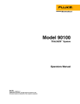
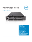
2.2.7 Next generation Dell Embedded Server Management
The chart below shows the components of the new embedded server management capability. As a
700-series enterprise product, T710 comes standard with BMC and iDRAC Express. The iDRAC
Express hosts the Lifecycle Controller and Unified Server Configurator. Optional iDRAC Enterprise
provides out-of-band management capabilities and enables the optional V-Flash.
See Section 20.2 “Embedded Server Management”.
Figure 2.
Embedded Server Management Capability
3
System Overview
3.1
Overview/Description
•
•
Customer driven product priorities
o Best performance and availability in a two-socket tower
o Large Storage footprint, best I/O capability
Product Positioning
o Industry leading performance and availability in a two-socket tower
o In direct competition with the HP ML370, IBM x3500
4
DELL
PowerEdge T710 Technical Guidebook
•
•
Target Market
o Corporate workgroups in remote sites running critical apps requiring 24 x 7 uptime
o Supports applications across Data Access and Data Processing
o Virtualization
o Retail space, Digital signage, TV walls
Key Features
o Dual IOH, up to 16 drives in one volume, 18 DIMMS, 4x LOMs, all HA in base, 4 x 25 W
PCI
3.2
T710 Product Features Summary
Table 2.
PowerEdge T710 Features and Descriptions
Feature
Details
Processor
Intel Xeon 5500 Series,1,86GHz – 2.93GHz, 60W, 80W, 95W, See Section 8.3
“Supported Processors”.
Front Side Bus
Intel Quick Path Interconnect (QPI) 4.8 – 6.4 GT/s
# Processors
1 or 2
# Cores
2 or 4
L2/L3 Cache
256 K per core L2, 4MB – 8MB shared L3
Chipset
Intel 5520 chipset
DIMMs/Speed
1, 2, 4, 8 GB UDIMM and RDIMM @ 1066 and 1333 MHz
Certain memory configurations clock down to 800 MHz
Min/Max RAM
1GB/144 GB
HD Bays
8 X 3.5” or 16 X 2.5”, 3Gb SAS
HD Types
SSD, SAS, SATA are supported
Ext Drive Bay(s)
Two full height peripheral bays
Int. HD Controller
None
Opt. HD Controller
Perc 6/i or SAS 6/iR in dedicated storage slot
BIOS
Dell BIOS core 11G implementation. See Section 11 “BIOS”.
Video
Integrated Matrox G200 with iDRAC6
Availability
Hot swap HDD, hot swap redundant power supplies, hot swap redundant fans
Server Mgt.
iDRAC6 Express, Optional iDRAC6 Enterprise, Optional VFlash
I/O Slots
6 PCIe Gen 2 expansion slots + 1 dedicated controller slot
RAID
0, 1, 5, 10, 50, 60. See Section 14.6 “RAID Configurations”.
NIC/LOM
2 X Broadcom 5709 1GBe LOMs (4 ports total). TOE enabled, Optional iSCSI
offload
USB
Two front, six rear, one internal
Power Supplies
Optional redundant 1100 W. Climate Saver Gold
Front Panel
Active LCD, rotates 90 degrees for rack mounting
System ID
System ID for PR T710:: 0x029B
5
DELL
PowerEdge T710 Technical Guidebook
Feature
Details
Fans
4 X hot swap redundant
Chassis
5U rackable tower
4
Mechanical
4.1
Chassis Description
The T710 system uses a tower or rack mount 5U chassis. It is classified by Dell as a rackable tower,
meaning it is optimized for tower operation
4.2
Dimensions and Weight
Figure 3.
Table 3.
T710 Dimensions
Detailed Dimensions
Xa
Xb
Ya
Yb
Yc
Za
with
bezel
Za
without
bezel
Zb
Zc
217.9 mm
304.4 mm
431.3
mm
466.3
mm
471.3
mm
37 mm
35 mm
659.6
mm
694.8
mm
8.6 in
12.0 in
17.0 in
18.4 in
18.6 in
1.5 in
1.4 in
26.0 in
27.4 in
Weight (maximum configuration) 35.3 kg (78 lb)
6
DELL
PowerEdge T710 Technical Guidebook
4.3
Front Panel View and Features
Peripheral
Bays, 2HH
Control Panel
and LCD
Front
USB (2)
Figure 4.
4.4
Front Panel View and Features
Back Panel View and Features
PCIe Slots
LOMs
iDRAC Enterprise
USB
Figure 5.
Back Panel View and Features
7
DELL
PowerEdge T710 Technical Guidebook
4.5
Power Supply Indicators
T710 power supplies have embedded cooling fans and one bi-colored status LED.
Status States:
•
•
•
•
4.6
Off – LED is dark
AC source applied – solid green LED
Fault of any kind – solid amber LED
DC enable applied – solid green LED (no change from AC applied)
Side Views and Features
Figure 6.
Figure 7.
Side Views and Features
Fold-out Feet Add Additional Stability
8
DELL
PowerEdge T710 Technical Guidebook
4.7
Internal Chassis Views
Figure 8.
Internal Chassis Overview
Backplane Cables
Controller
Slot
PCIe Slots
DIMM Slots
Backplane
Processors
Figure 9.
4.8
Internal Chassis Detailed View
Rails and Cable Management
The T710 Rack Kit has rack installation components, such as rails. The rack installation components
consist of sliding rack mount rails with the latest generation Cable Management Arm (CMA). T710
features slam latches to offer easier removal from the rack.
9
DELL
PowerEdge T710 Technical Guidebook
Figure 10. New Cable Management Arm
•
•
All steel construction – eliminates creep/sag
More open area for air flow
When the system is installed in a rack, please observe the following guidelines:
•
•
•
4.9
Nothing should be located within 12” of the front of the unit that could restrict the air flow into the
system.
Nothing should be mounted or placed behind the chassis that would restrict airflow from exiting
the system. Only Dell approved CMAs can be placed behind the chassis. All other objects
should be located at least 24” away from the rear of the chassis.
When two systems are placed back-to-back, the separation between the units should be at least
24” if the exit airflow is equivalent for the two chassis. This allows exit air to escape without
creating an extreme back pressure at the rear of one of the chassis.
Rack View
Figure 11. T710 Rack View
For more rack, rail, and CMA information see Section 17 “Rack Information”.
4.10 Fans
Four 92mm single-rotor hot-pluggable fans are mounted in the rear of the cooling shroud. Each fan has
a single-wire harness that plugs into the planar fan connectors (FAN1 through FAN4).
10
DELL
PowerEdge T710 Technical Guidebook
Figure 12. Fans
The Embedded Server Management logic in the system controls and monitors the speed of the fans. A
fan speed fault or over-temperature condition results in a notification by ESM.
T710 Power Supply Units have integrated fans. The system requires a blank module in place of the
empty power supply slot.
System fan speed is pulse-width modulated. Optional redundant cooling is supported with only one
rotor failing at a time (system may throttle when a rotor fails).
Note
Do not place any physical obstructions in the front (at least 12”) or rear (at least 24”) of the T710
chassis. This may cause a decrease in airflow, resulting in an over-temperature condition.
Placement of non-redundant fans must be at the rearmost section of the shroud. Do not operate the
system without the cooling shroud installed.
4.11 Control Panel/LCD
The system control panel is located on the front of the system chassis to provide user access to
buttons, display, and I/O interfaces.
Figure 13. Control Panel/LCD View
11
DELL
PowerEdge T710 Technical Guidebook
Features of the system control panel include:
•
128x20 pixel LCD panel with controls
o Two navigation buttons
o One select button
o One system ID button
• ACPI-compliant power button with an integrated green power LED
• Non-Maskable Interrupt (NMI) button (recessed)
• Ambient temperature sensor
• LCD panel can rotate 90 degrees for optional rack mounting of the server
• Two external USB 2.0 connectors
The LCD panel is a graphics display controlled by the iDRAC, unlike the 9G panel that had its own
CPLD. Error codes can be sent to the display by either ESM or BIOS.
BIOS has the ability to enter a “Secure Mode” through setup, which locks the power and NMI buttons.
When in this mode, pressing either button has no effect and does not mask other sources of NMI and
power control.
4.11.1
Cover Latch
A tool-less latch is integrated in the side cover to secure it to the tower chassis. It is lockable.
Figure 14. Cover Latch
4.11.2
Bezel
A metal bezel is mounted to the chassis front to provide the Dell ID. A lock on the bezel prevents unauthorized access to system HDD(s). System status (via the LCD) is viewable when the bezel is
installed.
The bezel is standard for the T710 system.
12
DELL
PowerEdge T710 Technical Guidebook
Figure 15. T710 Bezel
4.11.3
Hard Drive
The front bezel of the system contains a lock. A locked bezel secures the system hard drives.
4.11.4
Trusted Platform Management (TPM)
The TPM generates/stores keys, protects/authenticates passwords, and creates/stores digital
certificates. TPM can also enable the BitLocker™ hard drive encryption feature in Windows Server
2008.
TPM is enabled through a BIOS option and uses HMAC-SHA1-160 for binding. There are different
planar PWA part numbers to accommodate the different TPM solutions. The Rest of World (ROW)
version has the TPM soldered onto the planar. The other version of the planar has a connector for a
plug-in module (Factory Install Only).
China TPM (TCM) is a post-RTS feature. Until China TCM is available, T710 units shipped to
customers in China contain a no TPM motherboard.
4.11.5
Power-Off Security
BIOS has the ability to disable the power button function.
4.11.6
Intrusion Alert
A switch mounted on the cooling shroud detects chassis intrusion. When the cover is opened, the
switch circuit closes to indicate intrusion to ESM. When enabled, the software provides notification that
the cover has been opened.
4.11.7
Secure Mode
BIOS has the ability to enter a secure boot mode via Setup. This mode includes the option to lock out
the power and NMI switches on the control panel or set up a system password.
13
DELL
PowerEdge T710 Technical Guidebook
4.12 Persistent Storage
T710 offers two types of persistent storage: managed (iDRAC6 Express/iDRAC6 Enterprise) and
unmanaged internal persistent storage.
One of the unmanaged ports is for an optional SD card and the other is for a USB key.
Figure 16. Persistent Storage Block Diagram
4.12.1
Managed Persistent Storage
iDRAC6 Express is a managed persistent storage space for server provisioning data. The base
iDRAC6 express consists of 1 GB flash, and the optional Vflash is an external SD card on the optional
iDRAC6 Enterprise. The optional vflash offers the hot-plug portability and increased storage capacity
benefits of SD while managed by the system.
iDRAC6 is currently configured to support the following applications:
•
•
•
•
•
•
•
Unified Server Configurator Browser and System Services Module (SSM) (25 MB): the UEFI
browser provides a consistent graphical user interface for bare metal deployment and is ideal
for one-to-one deployment. The SSM supports automatic one-to-N deployment.
Service Diagnostics (15 MB): formerly on the hard drive as the Utility Partition, this is a bootable
FAT16 partition for Service Diagnostics
Deployment OS Embedded Linux (100 MB): storage space to hold Embedded Linux
Online Diagnostics (35 MB): non-bootable FAT32 partition for Online Diagnostics.
Deployment OS WinPE (200 MB): storage space to hold Windows Pre-installation Environment
Driver Store (150 MB): holds all files required for OS deployment.
iDRAC firmware (120 MB): holds the two most recent versions of iDRAC firmware
14
DELL
PowerEdge T710 Technical Guidebook
•
Firmware Images (160 MB): holds the two most recent versions of BIOS, RAID, LOM, power
supplies and hard drive firmware. This partition also holds the BIOS and option ROM
configuration data.
• Life Cycle Log (2 MB): stores initial factory configuration as well as all detectable hardware and
firmware changes to the server since its deployment. The Life Cycle Log is stored on the BMC
SPI flash.
Approximately 20 percent of the flash space is reserved for wear leveling on the NAND flash. Wear
leveling extends the life of the NAND flash by balancing the use cycles on the flash’s blocks.
4.12.2
SD Module (Unmanaged Internal Persistent Storage)
The optional Internal SD module is a dedicated port for an SD flash card for embedded Hypervisor for
virtualization. The SD flash card contains a bootable OS image for virtualized platforms.
Figure 17. T710 SD Module
Figure 18. SD Diagram
15
DELL
PowerEdge T710 Technical Guidebook
4.13 USB Key (Unmanaged Internal Persistent Storage)
T710 has one internal USB port on the motherboard for any USB key based security or license
application.
Some possible applications of the USB key:
•
•
•
User custom boot and pre-boot OS for ease of deployment or diskless environments
USB license keys for software applications like eToken™ or Sentinel Hardware Keys
Storage of custom logs or scratch pad for portable user defined information (not hot-pluggable)
4.14 Battery
A replaceable coin cell CR2032 3V battery mounted on the planar provides backup power for the RealTime Clock and CMOS RAM on the ICH. The battery is located under the fan assembly at the rear of
the motherboard, near the rear USB ports.
4.15 Field Replaceable Units (FRU)
Hot swap HDD and SSD, fans, and power supplies are the primary field replaceable units on T710.
The planar contains a serial EEPROM to store FRU information including Dell part number, part
revision level, and serial number. The Advanced Management Enablement Adapter (AMEA) contains a
FRU EEPROM. The backplane SEP and the power supply microcontroller are also used to store FRU
data.
5
Electrical
5.1
Clock Circuitry
System clock circuitry is based on Intel CK410B+ synthesizer and DB1200/DB900 driver specification.
A clock synthesizer device is a single chip solution. The CK410B+ synthesizes and distributes a
multitude of clock outputs at various frequencies, timings and drive levels using a single 14.318 MHz
crystal.
•
•
•
•
•
5.2
PCI Express Gen2 support
Host clock support (133 MHz)
Spread spectrum support
33 MHz, 48 MHz, 100 MHz clock support
14.318 MHz clock support
Volatility
See your Dell Representative for the current T710 Statement of Volatility.
6
Power, Thermal, and Acoustic
6.1
Power Supplies
The power supply subsystem consists of one or two AC-DC power supplies (1+1 redundant
configuration) connected to the planar through the PDB. The power supply only provides +12V and
+12Vaux. There are several voltage regulators in the system to supply different voltage levels needed
by different logic devices.
16
DELL
PowerEdge T710 Technical Guidebook
6.2
Power Supply Specifications
The T710 power supply is rated at 1100 W. It operates on input voltages ranging from 90 – 264 V, autoswitching to the sensed line level.
•
•
EMC classification is Light Industry
FCC classification is Class A
Table 4.
Power Supply Specifications
Minimum
Typical
Maximum
Vin (Voltage first range)
90 V
115/230
264 V
Vin (frequency)
47 Hz
50/60 Hz
63 Hz
Iin (90 VAC)
–
–
13.5 A
Iin(100 VAC)
–
–
12.0 A
Iin (180 VAC)
–
–
7.0 A
Initial In-rush Current
–
–
55 A
Secondary In-rush Current
–
–
35 A
The base redundant system consists of two hot-plug 1100 W power supplies in a 1+1 configuration.
The power supplies connect indirectly to the planar via the Power Distribution Board (PDB). Two power
cables connect between the PDB and the backplane. Another multi-drop cable also connects the PDB
to the optical and/or tape drives. The PS bay sheet metal prevents unsupported power supplies from
being installed in a T710 system.
T710 power supplies have embedded cooling fans and one bi-colored status LED.
Status States:
•
•
•
•
Off – No LED
AC source applied – Solid Green LED
Fault of any kind – Solid Amber LED
DC enable applied – Solid Green LED (no change from AC applied)
Starting with 11G, the power supplies no longer have a FRU EEPROM; FRU data is now stored in the
memory of the PSU Microcontroller. Additionally, the PSU Firmware can now be updated by iDRAC
over the PMBus. Power is soft-switched, allowing power cycling via a switch on the front of the system
enclosure or via software control (through server management functions). The power system is
compatible with industry standards, such as ACPI and the Microsoft Windows Server H/W Design
Guide.
17
DELL
PowerEdge T710 Technical Guidebook
Figure 19. T710 Power Supply
If using only one power supply, the single PSU should be installed in the PS1 bay and a PSU Close Out
(metal cover) is installed in the PS2 bay. The use of the PS1 bay for the single PSU configuration is
done for consistency only. Nothing prevents the use of the PS2 bay in a single PSU configuration.
6.3
Power Efficiency
Table 5.
T710 Power Supply Efficiency
Efficiency at 115 V Input Voltage
20% Loading
87%
50% Loading
90%
100% Loading
87%
Efficiency at 230 V Input Voltage
10% Loading
80%
20% Loading
88%
50% Loading
92%
100% Loading
88%
One of the main features of the latest family of Dell servers is enhanced power efficiency. T710
achieves higher power efficiency by implementing the following features:
•
•
•
•
•
•
•
•
•
•
•
•
User-selectable power cap (subsystems will throttle to maintain the specified power cap)
Improved power budgeting
Larger heat sinks for processors and IOH
Accurate inlet temperature
PSU/VR efficiency improvements
Switching regulators instead of linear regulators
Closed loop thermal throttling
Increased rear venting/3D venting
PWM fans with an increased number of fan zones and configuration-dependent fan speeds
Use of DDR3 memory (lower voltage, UDIMM support)
CPU VR dynamic phase shedding
Memory VR static phase shedding
18
DELL
PowerEdge T710 Technical Guidebook
•
•
•
•
•
•
•
•
6.4
Random time interval for system start
Allows an entire rack to power on without exceeding the available power
BIOS Power/Performance options page
BIOS-based CPU P-state manager (power management in a virtualized environment)
Ability to slow down or power down memory
Ability to disable a CPU core
Ability to turn off items not being used (i.e. USB ports, LOMs, PCIe slots, etc.)
Option to run PCIe at Gen1 speeds instead of Gen2 (BIOS setup option)
Environmental Specifications
Table 6.
Environmental Specifications
Temperature
Operating
10° to 35°C (50° to 95°F) with a maximum temperature gradation
of 10°C per hour
Note: For altitudes above 2950 feet, the maximum operating
temperature is de-rated 1°F/550 ft.
Storage
-40° to 65°C (-40° to 149°F) with a maximum temperature
gradation of 20°C per hour
Relative Humidity
Operating
20% to 80% (non-condensing) with a maximum humidity
gradation of 10% per hour
Storage
5% to 95% (non-condensing) with a maximum humidity gradation
of 10% per hour
Maximum Vibration
Operating
0.26 Grms at 5 – 350 Hz in operational orientations
Storage
1.54 Grms at 10 – 250 Hz in all orientations
Maximum Shock
Operating
Half-sine shock in all operational orientations of 31 G ± 5% with a
pulse duration of 2.6 ms ± 10%
Storage
Half-sine shock on all six sides of 71 G ± 5% with a pulse
duration of 2 ms ± 10%
Square wave shock on all six sides of 27 G with velocity change
@ 235 in/sec or greater
Altitude
Operating
-16 to 3048 m (-50 to 10,000 ft)
Note: For altitudes above 2950 feet, the maximum operating
temperature is de-rated 1°F/550 ft.
Storage
-16 to 10,600 m (-50 to 35,000 ft)
19
DELL
PowerEdge T710 Technical Guidebook
6.6
Maximum Input Amps
The T710 system exhibits the following maximum current draw at the stated voltages:
•
•
•
•
•
•
6.7
13.7A maximum at 90 VAC
12.0A maximum at 100 VAC
10.4A maximum at 115 VAC
5.75A maximum at 208 VAC
5.45A maximum at 220 VAC
5.2A maximum at 230 VAC
EnergySmart Enablement
T710 does not support a separate EnergySmart configuration as was offered with certain 10 G servers.
A 750 W EnergySmart power supply option is under investigation, but will not be available at RTS.
Certain other EnergySmart options may be made available in the future.
6.8
Energy Star Compliance
The final Energy Star specification for servers was issued in mid-May, 2009. Work is underway to
determine which configurations of T710 will be Energy Star compliant. This section will be updated
accordingly.
6.9
Acoustics
The acoustical design of the PowerEdge T710 reflects:
•
•
•
•
Adherence to Dell’s high sound quality standards. Sound quality is different from sound power
level and sound pressure level in that it describes how humans respond to annoyances in
sound, like whistles, hums, etc. One of the sound quality metrics in the Dell specification is
prominence ratio of a tone, and this is listed in the table below.
Office environment acoustics. Compare the values for LpA in Table 7 to see that they are lower
than ambient noise levels of typical office environments.
Hardware configurations affect system noise levels. Dell’s advanced thermal control provides
for optimized cooling with varying hardware configurations. Some of the perhaps less intuitive
but potentially important decision-making configuration examples are listed below.
o Most typical configurations perform as listed in Table 7.
o However, some less typical configurations and components can result in higher noise
levels. Examples of acoustical performance for non-typical hardware configurations are
shown in Table 7.
o The dBA values are not additive, e.g., incorporating a change for 2 dBA reduction and
another change for 3 dBA does not generally produce a 5 dBA reduction.
Noise ramp and descent at Boot-up. Fan speed noise levels ramp during the boot process to
add a layer of protection for component cooling if the system does not boot properly.
20
DELL
PowerEdge T710 Technical Guidebook
Table 7.
PowerEdge T710 3.5” HDD System
Typical: 4x Y847J fans, 2x 80 W
M399F CPUs, 5x GX198 146 GB 15
KRPM HDDs, 6x 2-GB D841D
DIMMs, 2x 1100-W Y613G Power
Supplies, PERC6/i YK838 card, 2x
X3959 NIC PCI cards, 1x DVD Drive
at 23° C
Non-Typical Hardware
Configurations; Same as Above
Except with Following PCI cards
PowerEdge T710 2.5” HDD System
Typical: 4x Y847J fans, 2x 80 W
M399F CPUs, 5x 2.5” 73 GB 15
KRPM SAS HDDs, 6x 2-GB D841D
DIMMs, 2x 1100-W Y613G Power
Supplies, PERC6/i YK838 card, 2x
X3959 NIC PCI cards, 1xDVD Drive
at 23° C
T710’s Prominence Ratio to Tone
Operating
Mode
LwA-UL,
bels
LpA, dBA
Tones
Standby
2.7
13
No prominent
tones
Idle
5.9
40
No prominent
tones
Active Hard Disk
Drives
6.0
42
No prominent
tones
Stressed
Processor,
SPECPower at
50% loading
5.9
40
No prominent
tones
10 Gb NIC, Idle
6.0
42
No prominent
tones
PERC6/E, Idle
6.0
42
No prominent
tones
4+ PCI cards
installed
6.2
44
No prominent
tones
Standby
2.7
13
No prominent
tones
Idle
5.7
38
No prominent
tones
Active Hard Disk
Drives
5.7
39
No prominent
tones
Stressed
Processor,
SPECPower at
50% loading
5.7
38
No prominent
tones
21
DELL
PowerEdge T710 Technical Guidebook
7
Block Diagram
Figure 20. T710 Block Diagram
8
Processors
8.1
Overview
The Intel 5500 two-socket processor is the IA-32 microprocessor designed specifically for servers and
workstation applications. The processor is based on new Core micro-architecture; however, it is 100
percent compatible with existing IA-32 software. Selective Intel Xeon 5500 series two-socket SKUs also
support Turbo Mode. Turbo Mode is an OS-controlled operation that automatically allows the processor
to run faster than the marked frequency if the CPU is operating below power, temperature, and current
limits.
The Intel Xeon 5500 series two-socket processor utilizes a 1366-contact Flip-Chip Land Grid Array (FCLGA) package that plugs into a surface mount socket.
Table 8.
Intel Xeon 5500 Series Features
Intel Xeon 5500 series
Two-Socket Processor
Features
Cache size
32 KB instruction
32 KB data
4 or 8 MB
(shared)
Multi-processor support
1-2 CPUs
Package
LGA1366
22
DELL
PowerEdge T710 Technical Guidebook
8.2
Features
The Intel 5500 two-socket processor supports all Streaming SIMD Extensions (including SSE2, SSE3,
and SSE4) and Intel 64 instructions.
Key features:
•
•
•
•
•
•
•
•
•
•
•
•
•
•
•
•
•
•
•
8.3
Four or two cores per processor
Two point-to-point QPI links at 6.4 GT/s
1366-land FC-LGA package
No termination required for non-populated CPUs (must populate CPU socket 1 first)
Integrated QuickPath DDR3 memory controller
64-byte cache line size
RISC/CISC hybrid architecture
Compatible with existing x86 code base
Optimized for 32-bit code
MMX support
Execute Disable Bit
Intel Wide Dynamic Execution
o Executes up to four instructions per clock cycle
Simultaneous Multi-Threading (SMT) capability
Support for CPU Turbo Mode (on certain SKUs)
o Increases CPU frequency if operating below thermal, power, and current limits
Streaming SIMD (Single Instruction, Multiple Data) Extension 4
Intel 64 Technology
Intel VT-x and VT-d Technology for virtualization support
Enhanced Intel SpeedStep Technology
Demand-based switching for active CPU power management as well as support for ACPI PStates, C-States, and T-States
Supported Processors
All processors are branded as Intel Xeon and a 256K L2 cache per core. Please go to Dell.com or
contact your Dell representative for the most up-to-date offering.
Table 9.
Supported Processors and Descriptions
Model
Speed
Power
QPI
L3 Cache
Features
Cores
X5570
2.93 GHz
95 W
6.4 GT/s
8M
Turbo +3, HT
4
X5560
2.80 GHz
95 W
6.4 GT/s
8M
Turbo +3, HT
4
X5550
2.66 GHz
95 W
6.4 GT/s
8M
Turbo +3, HT
4
E5540
2.53 GHz
80 W
5.86 GT/s
8M
Turbo +2, HT
4
E5530
2.40 GHz
80 W
5.86 GT/s
8M
Turbo +2, HT
4
E5520
2.26 GHz
80 W
5.86 GT/s
8M
Turbo +2, HT
4
L5520
2.26 GHz
60 W
5.86 GT/s
8M
Turbo +2, HT
4
E5506
2.13 GHz
80 W
4.8 GT/s
4M
–
4
23
DELL
PowerEdge T710 Technical Guidebook
8.4
Model
Speed
Power
QPI
L3 Cache
Features
Cores
E5504
2.00 GHz
80 W
4.8 GT/s
4M
–
4
E5502
1.86 GHz
80 W
4.8 GT/s
4M
–
2
Processor Configurations
T710 provides support for up to two Intel 5500 two-socket processors.
A single processor placed in the CPU1 socket functions normally; however, T710 systems require a
CPU blank in the CPU2 socket for thermal reasons. The system is held in reset if a single processor is
placed in the CPU2 socket.
8.5
Additional Processor Information
Voltage regulation to the Intel 5500 two-socket processor is provided by EVRD (Enterprise Voltage
Regulator-Down). EVRDs are embedded on the planar. CPU core voltage is not shared between
processors. EVRDs support static phase shedding and power management via the PMBus.
9
Memory
9.1
Overview
T710 utilizes DDR3 memory providing a high performance, high-speed memory interface capable of
low-latency response and high throughput. T710 supports Registered ECC DDR3 DIMMs (RDIMM) or
Unbuffered ECC DDR3 DIMMs (UDIMM).
The DDR3 memory interface consists of three channels. The maximum number of supported DIMMs is
dependent on the type of DIMM used
Table 10.
9.2
DIMM Configurations
DIMM Type
Maximum Configuration
Single or dual rank RDIMM
3 per channel per processor (18 total)
Quad rank RDIMM
2 per channel per processor (12 total)
Single or dual rank UDIMM
2 per channel per processor (12 total)
DIMMs Supported
T710’s DDR3 interface supports 2, 4, 8, or 16 GB RDIMMs and 1 GB or 2 GB UDIMMs.
9.3
Memory Population Scenarios
The memory mode is dependent on how the memory is populated in the system.
•
•
Three channels populated per CPU
o Typically, the system runs in Independent Channel mode in this configuration. This
mode offers the most DIMM population flexibility and system memory capacity, but offers
the least number of RAS (reliability, availability, service) features.
o All three channels must be populated identically.
o Maximum memory bus speed is 800 MHz
Two channels (CH 2 and CH 1) are populated identically per CPU; third channel is unused.
24
DELL
PowerEdge T710 Technical Guidebook
When mirroring is enabled, the memory image in Channel 2 is maintained the same as
Channel 1.
o Typically, two channels operate in Advanced ECC (Lockstep) mode with each other by
having the cache line split across both channels. This mode provides improved RAS
features (SDDC support for x8-based memory).
o For memory mirroring, the two channels operate as mirrors of each other – writes go to
both channels and reads alternate between the two channels. The channels are no
longer in lockstep mode.
• One channel is populated per CPU
o This is a simple Memory Optimized (Independent) mode. Mirroring is not supported.
The T710 memory interface supports memory demand and patrol scrubbing, single-bit correction, and
multi-bit error detection. Correction of a x4 or x8 device failure is also possible through the lockstep
channel mode and the SDDC code. Additionally, correction of a x4 device failure is possible through the
independent channel mode.
o
9.4
Slots/Risers
The T710 has 18 DIMM slots on the motherboard. No memory risers are utilized. Nine DIMM slots are
associated with each processor. Both processors must be populated to utilize all 18 DIMM slots.
Figure 21. T710 Motherboard
9.5
Speed/Memory Features
Key features of the T710 memory system include:
•
•
•
•
•
•
•
•
•
•
•
Registered (RDIMM) and Unbuffered (UDIMM) ECC DDR3 technology
Each channel carries 64 data and eight ECC bits
Support for up to 144 GB of RDIMM memory (with 18 x 8 GB RDIMMs)
Support for up to 24 GB of UDIMM memory (with 12 x 2 GB UDIMMs)
Support for 1066/1333 MHz single and dual rank DIMMs
Support for 1066 MHz quad rank DIMMs
800 MHz DIMMs are only used in testing
Single DIMM configuration only with 1 GB DIMM at socket DIMM A1
Support ODT (On Die Termination)
Clock gating (CKE) to conserve power when DIMMs are not accessed
DIMMs enter a low power self-refresh mode
25
DELL
PowerEdge T710 Technical Guidebook
•
•
•
•
•
•
•
•
9.6
I2C access to SPD EEPROM for access to RDIMM thermal sensors
Single Bit Error Correction
SDDC (Single Device Data Correction – x4 or x8 devices)
Support for Closed Loop Thermal Management
Multi Bit Error Detection
Support for Memory Optimized Mode
Support for Memory Mirroring
Support for Independent channel mode
Memory Population
Across CPU sockets, DIMM populations can be different as long as the population rules for each socket
are followed. Additionally, both CPU sockets operate in the same RAS mode and are set up with the
same memory timing parameters.
•
•
•
•
•
•
9.7
If DIMMs of different speeds are mixed, all channels operate at the fastest common frequency.
RDIMMs and UDIMMs cannot be mixed.
The first DIMM slot in each channel is color-coded with white ejection tabs for ease of
identification.
The first DIMM slot in each channel is color-coded with white ejection tabs for ease of
installation.
The DIMM sockets are placed 450 mils (11.43 mm) apart, center-to-center in order to provide
enough space for sufficient airflow to cool stacked DIMMs.
The T710 memory subsystem supports up to 18 DIMMs. DIMMs must be installed in each
channel starting with the DIMM farthest from the processor. Population order will be identified by
the silkscreen designator and the System Information Label (SIL) located on the chassis cover.
See the figure below for DIMM naming and numbering.
o Memory Optimized (Independent): {1, 2, 3}, {4, 5, 6}, {7, 8, 9}
o Advanced ECC (Lockstep) or Mirrored: {2,3}, {5, 6}, {8, 9}
o Quad Rank or UDIMM: {1, 2, 3}, {4, 5, 6}
Memory Speed Limitations
The memory frequency is determined by a variety of inputs:
•
•
•
Speed of the DIMMs
Speed supported by the CPU
Configuration of the DIMMs
Table 10 shows the memory populations and the maximum frequency achievable for that configuration.
Note
For Quad Rank DIMMs mixed with Single or Dual Rank DIMMs, the QR DIMM needs
to be in the slot with the white ejection tabs (the first DIMM slot in each channel).
There is no requirement for the order of SR and DR DIMMs.
26
DELL
PowerEdge T710 Technical Guidebook
Table 11.
DIMM
Type
UDIMM
RDIMM
9.8
DIMM Population and Maximum Achievable Frequency
DIMM 0
DIMM 1
DIMM 2
# of
DIMMs
800
1066
1333
SR
–
–
1
DR
–
–
1
SR
SR
–
2
SR
DR
–
2
DR
DR
–
2
SR
–
–
1
DR
–
–
1
QR
–
–
1
SR
SR
–
2
SR
DR
–
2
DR
DR
–
2
QR
SR
–
2
QR
DR
–
2
QR
QR
–
2
SR
SR
SR
3
SR
SR
DR
3
SR
DR
DR
3
DR
DR
DR
3
Mirroring
Memory mirroring is supported on memory configurations 29 (64GB) and 35 (32GB).
10
Chipset
10.1 Overview
The T710 motherboard incorporates the Intel 5500-EP chipset for I/O and processor interfacing. The
Intel 5500 chipset supports Intel’s 5500 two-socket processor family, QPI interconnect, DDR3 memory
technology, and PCI Express Generation 2. The Intel 5500 chipset consists of the Intel-5500 36D Dual
IOH and ICH9.
10.2 Intel 5500 Chipset Dual I/O Hub (IOH)
The T710 motherboard incorporates the Intel 5500 chipset 36D Dual IOH to provide a link between the
Intel 5500 two-socket processors and I/O components. The main components of the IOH consist of two
full-width QPI links (one to each processor), 72 lanes of PCIe Gen2, and a x4 ESI link to connect
directly to the South Bridge.
The IOH supports a special mode to work with DP processors that allow two IOHs to appear as a single
IOH to the processors in the system. This mode results in special behavior in the link and protocol
27
DELL
PowerEdge T710 Technical Guidebook
layers. Each IOH has a unique NodeID for communication between each other, but only the legacy
IOH’s NodeID are exposed to the CPU.
10.3 Intel Quickpath Architecture
The QuickPath Architecture consists of serial point-to-point interconnects for the processors and the
IOH. T710 has a total of four QuickPath Interconnect (QPI) links including one link connecting the
processors and links connecting both processors with the IOH and links connecting both IOHs. Each
link consists of 20 lanes (full-width) in each direction with a link speed of 6.4 GT/s. An additional lane is
reserved for a forwarded clock. Data is sent over the QPI links as packets.
The QuickPath Architecture implemented in the Intel 5500 chipset features four layers. The Physical
layer consists of the actual connection between components. It supports Polarity Inversion and Lane
Reversal for optimizing component placement and routing. The Link layer is responsible for flow control
and the reliable transmission of data. The Routing layer is responsible for the routing of QPI data
packets. Finally, the Protocol layer is responsible for high-level protocol communications, including the
implementation of a MESIF (Modify, Exclusive, Shared, Invalid, Forward) cache coherence protocol.
10.4 PCI Express Generation 2
PCI Express is a serial point-to-point interconnects for I/O devices. PCIe Gen2 doubles the signaling bit
rate of each lane from 2.5 Gb/s to 5 Gb/s. Each of the PCIe Gen2 ports are backwards-compatible with
Gen1 transfer rates.
10.5 Intel Direct Media Interface (DMI)
The DMI (previously called the Enterprise Southbridge Interface) connects the Intel 5500 chipset IOH
with the Intel I/O Controller Hub (ICH). The DMI is equivalent to a x4 PCIe Gen1 link with a transfer rate
of 1 GB/s in each direction.
Intel controller Hub 9/10 is a highly integrated I/O controller, supporting the following functions:
•
•
•
•
•
•
•
•
•
•
•
Six x1 PCIe Gen1 ports, with the capability of combining ports 1-4 as a x4 link
o These ports are unused on T710
PCI Bus 32-bit Interface Rev 2.3 running at 33 MHz
Up to six Serial ATA (SATA) ports with transfer rates up to 300 MB/s
o T710 features two SATA ports for optional internal optical drive or tape backup
Six UHCI and two EHCI (High-Speed 2.0) USB host controllers, with up to twelve USB ports
o T710 has eight external USB ports and two internal ports dedicated for UIPS and
embedded storage
Power management interface (ACPI 3.0b compliant)
Platform Environmental Control Interface (PECI)
Intel Dynamic Power Mode Manager
I/O interrupt controller
SMBus 2.0 controller
Low-Pin Count (LPC) interface to Super I/O, Trusted Platform Module (TPM), and SuperVU
Serial Peripheral Interface (SPI) support for up to two devices
o T710 BIOS is connected to the ICH using SPI
28
DELL
PowerEdge T710 Technical Guidebook
10.6 Super I/O Controller
The T710 system planar incorporates a SMSC LPC47M534 Super I/O controller to provide support for
the serial port and the keyboard controller.
The LPC47M534 is a plug and play compatible device that interfaces directly to the ICH through an
embedded LPC bus.
11
BIOS
11.1 Overview
The T710 BIOS is based on the Dell BIOS core and supports:
•
•
•
•
•
•
•
•
•
•
•
•
•
•
•
•
IA-32 Intel 5500 Two-Socket Support
Simultaneous Multi-Threading (SMT) support
CPU Turbo Mode support
PCI 2.3 compliant
Plug n’ Play 1.0a compliant
MP (Multiprocessor) 1.4 compliant
Boot from hard drive, optical drive, iSCSI drive, USB key, and SD card
ACPI support
Direct Media Interface (DMI) support
PXE and WOL support for on-board NICs
Memory mirroring
SETUP access through <F2> key at end of POST
USB 2.0 (USB boot code is 1.1 compliant)
F1/F2 error logging in CMOS
Virtual KVM, CD, and floppy support
UEFI (Unified Extensible Firmware Interface) 2.1 support
The T710 BIOS does not support:
•
•
•
Embedded diagnostics
BIOS language localization
BIOS recovery after bad flash (but can be recovered via iDRAC Express)
11.2 Supported ACPI States
PE T710 conforms to Advance Configuration and Power Interface Specification, v2.0c. and provides
support for ACPI P-States, C-States, and T-States.
12
Embedded NICs/LAN on Motherboard (LOM)
12.1 Overview
Two dual-port LAN controllers with support circuitry are embedded on the T710 system board as
independent Ethernet interface device. This provides four LOM ports at the rear of the server. Both
controllers are TOE enabled, with optional iSCSI offload engine.
29
DELL
PowerEdge T710 Technical Guidebook
The device is Broadcom 5709C Gigabit Ethernet controller. The following information details the
features of the LAN device:
•
•
•
•
•
•
•
•
•
•
•
•
•
13
x4 PCI Express Gen2 capable interface
o T710 operates dual-port controllers at Gen1 speed
MAC and PHY integrated
3072x18 Byte context memory
64 KB receive buffer
TOE (TCP Offload Engine)
iSCSI controller (enabled through an optional hardware key)
RDMA controller (RNIC) (enabled through an optional hardware key)
NC-SI (Network Controller-Sideband Interface) connection
Wake-On-LAN (WOL)
PXE 2.0 remote boot
iSCSI boot
IPv4 and IPv6 support
Bare metal deployment support
I/O Slots
13.1 Overview
The T710 comes standard with six PCIe (gen 2) expansion slots on the motherboard. A separate
dedicated slot is provided on the motherboard for the HDD controller. All PCIe slots are x8 connectors,
except the x16 slot. Slot specifications are shown below. See the motherboard diagram for slot
locations.
•
•
•
•
•
•
•
Slot 1 = half length, full height PCIe x4 link
Slot 2 = Full length, full height PCIe x16 link
Slot 3 = Full length, full height PCIe x8 link
Slot 4 = Half length, full height PCIe x8 link
Slot 5 = Half length, full height PCIe x8 link
Slot 6 = Half length, full height PCIe x8 link
Storage slot = PCIe x8 link
13.2 X16 Express Card Specifications
T710 supports x16 cards that meet the following requirements:
•
•
•
•
•
•
•
•
Standard height (4.376”)
Full length (12.283”)
Support for full bandwidth of x16 Gen2 link
No support for hot-plug or hot-removal
Maximum power of 25W
T710 provides +12V, +3.3V, and +3.3Vaux in accordance with Power Supply Rail Requirements
x16 slot is not compliant with the PCI Express x16 Graphics 150W-ATX Specification
x16 cards must be compliant with the PCI Express Card Electromechanical Specification Rev
2.0
30
DELL
PowerEdge T710 Technical Guidebook
•
•
•
x16 cards must only occupy the space of one slot. Cards that occupy the space of two slots are
not supported
x16 card is limited to 25 W initial start-up power until it is configured as a high-power device. If
no value is set for the Slot Power Limit, the card is limited to 25 W. The card must then scale
down to 25 W or disable operation per PCI Express Base Spec Rev 2.0
x16 card must be able to support a maximum operating temperature of 55°C as defined in the
Dell PCI Environmental Spec and the PCI Express Card Electromechanical Spec. T710
provides a minimum transverse air velocity of x LFM (linear feet per minute) to the x16 card.
13.3 Available PCIe Cards
T710 supports the following cards. Maximum supported and slot priorities shown.
Table 12.
Category
Internal Storage
(Integrated Slot)
External
Controllers
Card Priority
Description
Width
Slot Priority2
Maximum
Cards
100
Dell PERC 6/i Integrated
(No Sled)
x8 Gen1
Integrated
1
200
Dell SAS 6/iR Integrated
(No Sled)
x8 Gen1
Integrated
1
300
Dell SAS 5/E
x8 Gen1
Slot 6,4,2,5,3
2#3
400
Dell PERC 6/E 512
x8 Gen1
Slot 6,4,2,5,3
2#3
500
Dell PERC 6/E 256
x8 Gen1
Slot 6,4,2,5,3
2#3
600
Intel 10G Base-DA SFP+
Dual Port Adapter
x8 Gen1
Slot 6,4,2,5,3
4
700
Intel 10G Base-T Single
Port NIC
x8 Gen1
Slot 6,4,2,5,3
43
800
Broadcom® NetXtreme II®
57710 Single Port 10G
Base-T Ethernet PCIExpress Network Interface
Card with TOE and iSCSI
Offload
x8 Gen1
Slot 6,4,2,5,3
43
900
Intel 10G Base-SR Optical
Single Port NIC
x8 Gen1
Slot 6,4,2,5,3
4
1000
Dell SAS 5/iR
x8 Gen1
Slot 6,4,2,5,3
2#3
1100
Qlogic QLE2562 8Gbps
FC HBA, Dual Port
x8
Gen1/x4
Gen2
Slot 6,4,2,5,3
5
1200
Emulex LPe12002 8Gbps
FC HBA, Dual Port
x8
Gen1/x4
Gen2
Slot 6,4,2,5,3
5
1300
Qlogic QLE2560 8Gbps
FC HBA, Single Port
x8
Gen1/x4
Gen2
Slot 6,4,2,5,3
5
10 GB NICs
Internal Storage
FC8 HBA Single
Port
T710 Supported PCIe Cards and Descriptions1
31
DELL
PowerEdge T710 Technical Guidebook
Category
Card Priority
Description
Width
Slot Priority2
Maximum
Cards
1400
Emulex LPe12000 8Gbps
FC HBA, Single Port
x8
Gen1/x4
Gen2
Slot 6,4,2,5,3
5
1500
Qlogic QLE2462 FC4
HBA, Dual Port
x4 Gen1
Slot 6,4,2,5,3
5
1600
Qlogic QLE2460 FC4
HBA, Single Port
x4 Gen1
Slot 6,4,2,5,3
5
1700
Qlogic QLE220 FC4 HBA,
Single Port
x4 Gen1
Slot 6,4,2,5,3
5
1800
Emulex LPe11002 FC4
HBA, Dual Port
x4 Gen1
Slot 6,4,2,5,3
5
1900
Emulex LPe1150 FC4
HBA, Single Port
x4 Gen1
Slot 6,4,2,5,3
5
2000
LSI2032 PCIe SCSI HBA
x4 Gen1
Slot 6,4,2,5,3
2
2100
Intel PRO/1000VT 1G Cu
Quad Port NIC
x4 Gen1
Slot 6,4,2,5,3
5
2200
Intel PRO/1000PT 1G Cu
Dual Port NIC
x4 Gen1
Slot 6,4,2,5,3,1
6
2300
Broadcom 5709 IPV6 1G
CU Dual Port NIC
TOE/iSOE
x4 Gen1
Slot 6,4,2,5,3,1
6
2400
Broadcom 5709 IPv6 1G
Cu Dual Port NIC TOE
x4 Gen1
Slot 6,4,2,5,3,1
6
FC4 HBA
SCSI HBA
1 GB NICs
1.
For optimal performance, it is best to alternate slot population as Slot 6, 4, and 2, before starting Slot 5,3, and1.
2.
Slot 1 should be used for 1G NIC's only preferably.
3.
T710 supports up to four 25 W maximum power each (excluding internal storage slot) and up to two 15 W for the
remainder PCI-e cards regardless of which slots are populated. This restriction applies to any PCIe cards with a
maximum power over 15 W.
13.4 Boot Order
System boot order is settable in the BIOS
14
Storage
14.1 Overview
T710 supports a 16-drive backplane for 2.5” drives and an eight-drive backplane for 3.5” drives. There
are sixteen 2.5” or eight 3.5” hot-plug capable Serial Attached SCSI (SAS) or Serial ATA (SATA) slots
with two LED indicators per slot, two Mini-SAS cable connectors for connecting the backplane to the
integrated SAS 6/iR or PERC 6/i, a 10-pin planar signal connector, and an 8-pin PDB power connector.
SAS 6/iR is only supported on the 3.5” HDD backplane.
32
DELL
PowerEdge T710 Technical Guidebook
14.2 3.5” X8 HDD Backplane
The 3.5” HDD backplane has:
•
•
•
•
3.5” HDD are supported in this configuration
2.5” SSD in 3.5” carrier. Also max of 2x 2.5” SAS HDD in 3.5” carrier for entry SAS HDD price
point
Two Mini-SAS cables are used to connect both channels of the integrated SAS 6/iR or PERC 6/i
card to the eight-drive backplane.
For SATA/SAS mixing, two SAS drives are supported. In this configuration, one pair of drives
will be SAS and the remaining six drives will be SATA.
14.3 2.5” X16 HDD Backplane
The 2.5” HDD backplane has:
•
•
•
•
Only 2.5” HDD are supported in this configuration
One Mini-SAS cable is used to connect one channel of the integrated PERC 6/I (only) card to
the sixteen-drive backplane.
A SAS expander is used to map 16 HDD to the PERC (x4) controller
For SATA/SAS mixing, two SAS drives are supported. In this configuration, one pair of drives
will be SAS and the remaining fourteen drives will be SATA.
14.4 Storage Card Support Matrix
Table 13.
PERC
SAS/SATA
SAS HBA
SAS/SATA
Storage Card Support Matrix
SKU
Product
Usage
T710
Support
Slot
PCIe
Con
PCI
Bracket
PERC 6/i
Integrated
Internal
Backplane
Storage
(HDD, SSD)
Yes – Max 1
Storage
slot
x8
No
PERC 6/E
Adapter
External
SAS/SATA
Storage
Yes – Max 2
(MD1000
Pompano
and
MD1020
Ridgeback)
PCIe
slot
x8
Yes
PERC 5/E
Adapter
External
Legacy
Storage
Yes – Max 2
(MD1000
Pompano
only)
PCIe
slot
x8
SAS 6/iR
Integrated
Internal
Backplane
Storage
(No tape or
SSD support)
Yes – Max 1
Storage
slot
SAS 5/iR
Adapter
Internal SAS
Tape
Yes – Max 1
PCIe
slot
I/O
Con
RAID
BBU
0, 1, 5,
6, 10,
50, 60
BBU
x4 ext
x4 ext
0, 1, 5,
6, 10,
50, 60
TBBU
Yes
x4 ext
x4 ext
0, 1, 5,
10, 50
TBBU
x8
No
x4 int
x4 int
0, 1
No
x8
Yes
x4 int
N/A
No
x4 int
33
DELL
PowerEdge T710 Technical Guidebook
ICH
SATA
LSI 2032
SCSI
SKU
Product
Usage
T710
Support
Slot
PCIe
Con
PCI
Bracket
I/O
Con
RAID
BBU
SAS 5/E
Adapter
External SAS
(DAS, Tape)
Yes – Max 2
PCIe
slot
x8
Yes
x4 ext
x4 ext
None
No
On Planar
via chipset
Internal SATA
Optical and/or
Tape
(No HDD)
Yes 2 ports for
Optical
and/or Tape
N/A
N/A
N/A
x1 int
N/A
N/A
LSI 2032
Adapter
Internal/Extern
al SCSI Tape
or External
legacy SCSI
storage
Yes
SCSI(i
nt)
SCSI
(ext)
N/A
N/A
Yes - Max 2
PCIe
slot
x4
14.5 Available Drives
Table 14.
T710 Available Drives and Descriptions
Form Factor
Capacity
Speed
Type
2.5”
25 GB
N/A
SATA SSD
2.5”
50 GB
N/A
SATA SSD
2.5”
100 GB
N/A
SATA SSD
2.5”
73 GB
15 k
SAS HDD
2.5”
146 GB
15 k
SAS HDD
2.5”
146 GB
10 k
SAS HDD
2.5”
300 GB
10 k
SAS HDD
2.5”
160 GB
7.2 k
SATA HDD
2.5”
250 GB
7.2 k
SATA HDD
2.5”
500 GB
7.2 k
NL SAS HDD
3.5”
146 GB
15 k
SAS HDD
3.5”
300 GB
15 k
SAS HDD
3.5”
450 GB
15 k
SAS HDD
3.5”
600 GB
10 k
SAS HDD
3.5”
160 GB
7.2 k
SATA HDD
3.5”
250 GB
7.2 k
SATA HDD
3.5”
500 GB
7.2 k
SATA HDD
3.5”
750 GB
7.2 k
SATA HDD
3.5”
1000 GB
7.2 k
SATA HDD
3.5”
500 GB
7.2 k
NL SAS HDD
3.5”
750 GB
7.2 k
NL SAS HDD
3.5”
1000 GB
7.2 k
NL SAS HDD
34
DELL
PowerEdge T710 Technical Guidebook
14.6 RAID Configurations
T710 offers a wide array or RAID configurations from the factory to support the large drive capacity and the mixing of SSD, SAS, and SATA
drives. All configurations use the back plane connection type.
Table 15.
Configuration Type
Configurations
T710 RAID Configurations
Non-Mixed drives, all SATA, or all SAS,
or all SSD
Mixed SAS/ SATA
Non-RAID mix of SSD with
SAS/SATA not supported
Min 2xSAS+1xSATA
2.5” (2.5” chassis):
Max 2xSAS + 14xSATA
2.5” (3.5” chassis):
Max 2xSAS + 6xSATA
3.5”:
Max 2xSAS + 6xSATA
Max HDD
2.5” chassis/3.5”
chassis
Max HDD
2.5”
chassis/
3.5”
chassis
Description
Min HDD
SAS/SATA – No
RAID
0
MSS
Integrated SAS/SATA
No RAID (SAS 6/iR)
Min HDD
2.5” = not valid
2.5” = not valid
2.5” = not valid
2.5” = not valid
3.5” = 1
3.5” = 8
3.5” = 3 3.5” = 8
2.5” SSD = not valid
2.5” SSD = not valid
2.5” SSD = not valid
2.5” SSD = not valid
35
DELL
PowerEdge T710 Technical Guidebook
Configuration Type
Configurations
1
2.5” = not valid
3.5” = 2
2.5” = not valid
3.5” = 8
Min HDD
N/A
Integrated SSD/SAS/SATA
RAID 1 (SAS 6/iR)
2
Max HDD
2.5”
chassis/
3.5”
chassis
MSSR0
Integrated SSD/SAS/SATA
RAID 0 (PERC6iI)
SAS/SATA - RAID
Min HDD
Max HDD
2.5” chassis/3.5”
chassis
Description
Integrated SSD/SAS/SATA
RAID 0 (SAS 6/iR)
SAS/SATA - RAID
Non-Mixed drives, all SATA, or all SAS,
or all SSD
Mixed SAS/ SATA
Non-RAID mix of SSD with
SAS/SATA not supported
Min 2xSAS+1xSATA
2.5” (2.5” chassis):
Max 2xSAS + 14xSATA
2.5” (3.5” chassis):
Max 2xSAS + 6xSATA
3.5”:
Max 2xSAS + 6xSATA
2.5” = 2
3.5” = 2
2.5” = 16/8
3.5” = 8
2.5” = not valid
3.5” = 2
2.5” = not valid
3.5” = 2
MSSR1
N/A
Integrated SSD/SAS/SATA
RAID 1 (PERC6/i)
2.5” = 2
3.5” = 2
2.5” = 2
3.5” = 2
SAS/SATA - RAID
3
MSSR5
Integrated SSD/ SAS/SATA
RAID 5 (PERC 6/i )
2.5” = 3
3.5” = 3
2.5” = 16/8
3.5” = 8
N/A
SAS/SATA - RAID
4
MSSR6
Integrated SSD/SAS/SATA
RAID 6 (PERC 6/i)
2.5” = 4
3.5” = 4
2.5” = 16/8
3.5” = 8
N/A
SAS/SATA - RAID
5
MSSR10
Integrated SSD/SAS/SATA
RAID 10 (PERC 6/i )
2.5” = 4
3.5” = 4
2.5” = 16/8
3.5” = 8
N/A
36
DELL
PowerEdge T710 Technical Guidebook
Configuration Type
Configurations
Non-Mixed drives, all SATA, or all SAS,
or all SSD
Mixed SAS/ SATA
Non-RAID mix of SSD with
SAS/SATA not supported
Min 2xSAS+1xSATA
2.5” (2.5” chassis):
Max 2xSAS + 14xSATA
2.5” (3.5” chassis):
Max 2xSAS + 6xSATA
3.5”:
Max 2xSAS + 6xSATA
Min HDD
Max HDD
2.5” chassis/3.5”
chassis
Max HDD
2.5”
chassis/
3.5”
chassis
Description
Min HDD
SAS/SATA - RAID
6
MSSR50
Integrated SSD/SAS/SATA
RAID 50 (PERC 6/i )
2.5” = 6
3.5” = 6
2.5” = 16/8
3.5” = 8
N/A
SAS/SATA - RAID
7
MSSR60
Integrated SSD/SAS/SATA
RAID 60 (PERC 6/i )
2.5” = 8
3.5” = 8
2.5” = 16/8
3.5” = 8
N/A
SAS/SATA - RAID
8
MSSR1R1
Integrated SSD/SAS/SATA
RAID 1/RAID 1 (SAS 6/iR,
PERC 6/i)
2.5” = 2+2
3.5” = 2+2
2.5” = 2+2
3.5” = 2+2
N/A
SAS/SATA - RAID
9
MSSR1R5
Integrated SSD/SAS/SATA
RAID 1/RAID 5 (PERC 6/i)
2.5” = 2 + 3
3.5” = 2 + 3
2.5” = 2+14/6
3.5” = 2+ 6
N/A
SAS/SATA - RAID
13
MSSR1R6
Integrated SSD/SAS/SATA
RAID 1/RAID 6 (PERC 6/i)
2.5” = 2 + 3
3.5” = 2 + 3
2.5” = 2+14/6
3.5” = 2+ 6
N/A
SAS/SATA – No
RAID
10
MSS-X
Integrated SAS/SATA No
RAID (SAS 6/iR)
–
–
2.5” = not valid
3.5” = 3
2.5” = not valid
3.5” = 2+2
2.5”= not
valid
3.5”=6
37
DELL
PowerEdge T710 Technical Guidebook
Configuration Type
Configurations
Non-Mixed drives, all SATA, or all SAS,
or all SSD
Mixed SAS/ SATA
Non-RAID mix of SSD with
SAS/SATA not supported
Min 2xSAS+1xSATA
2.5” (2.5” chassis):
Max 2xSAS + 14xSATA
2.5” (3.5” chassis):
Max 2xSAS + 6xSATA
3.5”:
Max 2xSAS + 6xSATA
Max HDD
2.5” chassis/3.5”
chassis
Max HDD
2.5”
chassis/
3.5”
chassis
Description
Min HDD
Min HDD
Integrated SAS/SATA RAID
1/RAID 1 (SAS 6/iR)
SAS/SATA - RAID
11
–
MSSR1R1-X
–
–
Integrated SAS/SATA RAID
1/RAID 1 (PERC 6/i)
SAS/SATA - RAID
SSD/SAS - RAID
SSD/SAS - RAID
12
14
15
2.5” = not
valid
3.5” = 2+2
2.5” = 2+2
3.5” = 2+2
2.5” = 2 +
14/6
3.5” = 2 +
6
MSSR1R5-X
Integrated SAS/SATA RAID
1/RAID 5 (PERC 6/i)
–
–
MSSR0R1-X
Integrated SSD/SAS RAID
0/RAID 1 (PERC 6/i) RAID
0 set is SSD, RAID 1 set is
SAS
–
–
2.5” = 1 + 2
2.5” = 14 + 2
3.5” = 1 + 2 3.5” = 6 + 2
MSSR1R1-X
Integrated SSD/SAS RAID
1/RAID 1 (PERC 6/i) RAID
1 set is SSD, second RAID
1 set is SAS
–
–
2.5” = 2 + 2
2.5” = 2 + 2
3.5” = 2 + 2 3.5” = 2 + 2
–
38
DELL
PowerEdge T710 Technical Guidebook
Configuration Type
SSD/SAS - RAID
SSD/SAS - RAID
SSD/SAS - RAID
SSD/SAS - RAID
Non-Mixed drives, all SATA, or all SAS,
or all SSD
Mixed SAS/ SATA
Non-RAID mix of SSD with
SAS/SATA not supported
Min 2xSAS+1xSATA
2.5” (2.5” chassis):
Max 2xSAS + 14xSATA
2.5” (3.5” chassis):
Max 2xSAS + 6xSATA
3.5”:
Max 2xSAS + 6xSATA
Min HDD
Max HDD
2.5” chassis/3.5”
chassis
Max HDD
2.5”
chassis/
3.5”
chassis
MSSR1R5-X
Integrated SSD/SAS RAID
1/RAID 5 (PERC 6/i) RAID
1 set is SSD, RAID 5 set is
SAS
–
–
2.5” = 2 + 3
2.5” = 2 + 14
3.5” = 2 + 3 3.5” = 2 + 6
MSSR1R10-X
Integrated SSD/SAS RAID
1/RAID 10 (PERC 6/i)
RAID 1 set is SSD, RAID
10 set is SAS
–
–
2.5” = 2 + 4
2.5” = 2 + 14
3.5” = 2 + 4 3.5” = 2 + 4
MSSR1R50-X
Integrated SSD/SAS RAID
1/RAID 50 (PERC 6/i)
RAID 1 set is SSD, RAID
50 set is SAS
–
–
2.5” = 2 + 6
2.5” = 2 + 14
3.5” = 2 + 6 3.5” = 2 + 6
MSSR10R50-X
Integrated SSD/SAS RAID
10/RAID 50 (PERC 6/i)
RAID 10 set is SSD, RAID
50 set is SAS
–
2.5” = 4 + 6
2.5” = 8 + 8
3.5” = not valid 3.5” = not
valid
Configurations
16
17
18
19
Description
–
Min HDD
39
DELL
PowerEdge T710 Technical Guidebook
Configuration Type
Configurations
Non-Mixed drives, all SATA, or all SAS,
or all SSD
Mixed SAS/ SATA
Non-RAID mix of SSD with
SAS/SATA not supported
Min 2xSAS+1xSATA
2.5” (2.5” chassis):
Max 2xSAS + 14xSATA
2.5” (3.5” chassis):
Max 2xSAS + 6xSATA
3.5”:
Max 2xSAS + 6xSATA
Max HDD
2.5” chassis/3.5”
chassis
Max HDD
2.5”
chassis/
3.5”
chassis
Description
Min HDD
SSD/SAS/
SATA RAID
SSD/SAS/
SATA RAID
Integrated SSD/SAS/SATA
RAID 0/RAID 1/RAID 5
(PERC 6/i)
20
–
MSSR0R1R5-X
–
2.5” = 1 + 2 + 3
2.5” = 4 + 2 + 10
3.5” = 1 + 2 + 3
3.5” = 2 + 2 + 4
–
2.5” = 2 + 2 + 3
2.5” = 2 + 2 + 12
3.5” = 2 + 2 + 3
3.5” = 2 + 2 + 4
RAID 0 set is SSD, RAID 1
set is SAS, RAID 5 set is
SATA
Integrated SSD/SAS/SATA
RAID 1/RAID 1/RAID 5
(PERC 6/i)
21
–
MSSR1R1R5-X
RAID 1 set is SSD, second
RAID 1 set is SAS, RAID 5
set is SATA
Min HDD
40
DELL
PowerEdge T710 Technical Guidebook
Configuration Type
Configurations
Non-Mixed drives, all SATA, or all SAS,
or all SSD
Mixed SAS/ SATA
Non-RAID mix of SSD with
SAS/SATA not supported
Min 2xSAS+1xSATA
2.5” (2.5” chassis):
Max 2xSAS + 14xSATA
2.5” (3.5” chassis):
Max 2xSAS + 6xSATA
3.5”:
Max 2xSAS + 6xSATA
Max HDD
2.5” chassis/3.5”
chassis
Max HDD
2.5”
chassis/
3.5”
chassis
Description
Min HDD
SSD/SAS/
SATA RAID
22
MSSR10R1R5X
Integrated SSD/SAS/SATA
RAID 10/RAID 1/RAID 5
(PERC 6/i)
–
RAID 10 set is SSD, RAID
1 set is SAS, RAID 5 set is
SATA
–
Min HDD
2.5” = 4 +2 + 3
2.5” = 8 + 2 + 6
or
2.5” = 4 + 2 + 10
3.5” = not valid
3.5” = not valid
41
DELL
PowerEdge T710 Technical Guidebook
14.7 Internal Storage Controllers
T710 supports a choice of two internal 3GB SAS HDD controllers. The internal controller is placed in
the dedicated storage slot on the motherboard.
14.8 LED Indicators
Each disk drive carrier has two LED indicators visible from the front of the system. One is a green LED
for disk activity and the other is a bicolor (Green/Amber) LED for status information. The activity LED is
driven by the disk drive during normal operation. The bicolor LED is controlled by the SEP device on
the backplane. Both LEDs indicate certain conditions under direction of a storage controller.
14.9 Optical Drives
SATA optical drives are optional and connect to the planar via a SATA interface. IDE optical drives are
no longer supported. The following optical drives are available on T710: DVD-ROM and DVD+RW.
If the optical drive is not ordered with the system, a blank is installed in its place. In the absence of tape
drive, an optional second SATA optical drive is installed in the bay adjacent to the first optical drive.
14.10 Tape Drives
Tape drives are optional and connect to the planar via SATA/SCSI controller card/SAS controller card.
IDE tape drive is no longer supported. The following tape drives are available for usage on T710:
internal SATA, SCSI, and SAS drives; external SCSI and SAS drives.
If the tape drive is not ordered with the system, a blank is installed in its place.
T710 supports a number of internal tape backup options, plus the RD1000 disk backup unit. Only halfheight backup options are supported.
15
Video
15.1 Overview
The T710 system Integrated Dell Remote Access Controller (iDRAC6) incorporates an integrated video
subsystem, connected to the 32-bit PCI interface of the ICH. This logic is based on the Matrox G200.
The device only supports 2D graphics.
The integrated video core shares its video memory with the iDRAC’s 128 MB DDR2 application space
memory. This memory is also used for the KVM buffer.
The T710 system supports the following 2D graphics video modes:
Table 16.
Video Descriptions
Resolution
Refresh Rate (Hz)
Color Depth (bit)
640 x 480
60, 72, 75, 85
8, 16, 32
800 x 600
56, 60, 72, 75, 85
8, 16, 32
1024 x 768
60, 72, 75, 85
8, 16, 32
1152 x 864
75
8, 16, 32
1280 x 1024
60, 75, 85
8, 16
1280 x 1024
60
32
42
DELL
PowerEdge T710 Technical Guidebook
16
Audio
T710 does not support audio (sound card or speakers) as a system feature.
17
Rack Information
17.1 Overview
T710 shares the same rail kit and CMA as T610. The rails and CMA are 3U tall, but accommodate
systems that are 3U or greater in height such as T710 and T610 (both 5U). The rack kit includes ears
that bolt on the chassis and engage the rail latches.
17.2 Cable Management Arm (CMA)
The 3U CMA for T710 contains the following cables.
Table 17.
Cable Types and Amount Containable
Cable Type
# of Cables
Power
2
SAS
10
CAT6
2
Status LED
1
KVM dongle
1
Total
16
See Section 4.8 “Rails and Cable Management” for a picture of the new CMA.
17.3 Rack Configuration
In the rack configuration, the top painted panel is removed and two ears are bolted to the chassis. The
ears contain the slam latches that engage the rail latches.
43
DELL
PowerEdge T710 Technical Guidebook
Ears bolt to chassis for rack configuration
Ears Include slam latches to secure server in rack
Figure 22. T710 Rack Ears
17.4 Rails
Sliding ReadyRails™ for 4-post Racks:
Figure 23. T710 Sliding ReadyRails
•
•
•
•
•
•
•
Support for tool-less installation in 19” CEA-310-E compliant square hole 4-post racks including:
Support for Dell Clydesdale Racks (4220, 2420)
Support for Dell R2K Racks (4210, 2410)
Support for Dell Marconi Racks (4200, 2400)
Support for HP/Compaq 9xxx and 10xxx series racks
Support for HP/Compaq 7xxx series racks without the CMA
Support for tool-less installation in 19” CEA-310-E compliant round hole 4-post racks
44
DELL
PowerEdge T710 Technical Guidebook
•
•
•
•
•
•
18
Support for full extension of the system out of the rack to allow serviceability of key internal
components
Support for optional cable management arm (CMA)
Rail depth without the CMA: 760 mm
Rail depth with the CMA: 840 mm
Square-hole rack adjustment range: 692-756 mm
Round-hole rack adjustment range: 678-749 mm
Operating Systems
18.1 Overview
T710 supports all major enterprise server operating systems consistent with the Dell 11G server
portfolio.
18.2 Operating Systems Supported
Table 18.
Operating Systems
Microsoft Operating System
Installation
Factory
Install
Logo/Certification
Schedule
Small Business Server
2008
X64
Standard
Premium
FI
FI
WHQL
RTS
Small Business Server
2003 R2
32-bit x86
Standard
Premium
FI
WHQL
RTS
Standard
FI
Enterprise
FI
Standard
FI
x64
Enterprise
Datacenter
FI
FI
32-bit x86
Standard
No
Enterprise
No
Standard
No
Enterprise
No
Standard
FI
Enterprise
FI
Standard
FI
Enterprise
FI
Datacenter
DIB
Windows Server® 2008
and Windows Server
2008 SP2
Windows
Server 2003
32-bit x86
x64
32-bit x86
Windows
Server 2003 R2
x64
WHQL
RTS
RTS
RTS
WHQL
WHQL
WHQL
WHQL
RTS
RTS
RTS
RTS
RTS
RTS
RTS
RTS
RTS
WHQL
RTS
RTS
45
DELL
PowerEdge T710 Technical Guidebook
Table 19.
Linux Operating System
Operating Systems
Installation
Factory Install
Logo/Certification
Red Hat® Enterprise
Linux® 4.7
ES/AS x86-64
DIB, NFI
Yes
ES/AS x86
DIB, NFI
Yes
x86-64
FI
Yes
x86
DIB, NFI
Yes
SUSE Linux Enterprise
Server 10 x86-64 SP2
X86-64
FI (may change)
Yes
RTS
SUSE Linux Enterprise
Server 11
x86-64
FI
Yes
RTS
Table 20.
Solaris Operating System
Operating Systems
Installation
Factory Install
Logo/Certification
Schedule
Solaris 10 (latest update)
–
DIB, NFI
Yes
Post RTS
Red Hat Enterprise Linux
5.3
Schedule
RTS
RTS
RTS
RTS
RTS
RTS
RTS
RTS
TM
19
Virtualization
19.1 Overview
T710 has a primary mission as a virtualization platform for remote locations. Accordingly, the T710
supports all major virtualization options available from Dell, including VMware, Citrix XenServer and
Microsoft Hyper-V Server. Embedded options are available for VMware and Citrix XenServer.
Embedded options require the optional SD card module to be installed.
19.2 Virtualization Options Supported
Table 21.
Virtualization Options Supported
Operating Systems
Factory Install
Logo/
Certification
Schedule
Support for VMware ESX TM 3.5 update 4
and ESX 4.0
FI
Yes
RTS
Support for Microsoft Hyper-V (Viridian) TM
FI
Yes
RTS
Support for VMware ESXi 3.5 update 4
and ESXi 4.0 (embedded)
FI
Yes
RTS
Support for Citrix XenServer Enterprise®
5.x (embedded)
FI
Yes
RTS
Support for Microsoft Hyper-V server
(VSKU) (standalone)
FI
Yes
RTS
TM
46
DELL
PowerEdge T710 Technical Guidebook
20
Systems Management
20.1 Overview/Description
Dell aims on delivering open, flexible, and integrated solutions that help you reduce the complexity of
managing disparate IT assets by building comprehensive IT management solutions. Combining Dell
PowerEdge Servers with a wide selection of Dell-developed management solutions gives you choice
and flexibility, so you can simplify and save in environments of any size. To help you meet your server
performance demands, Dell offers Dell OpenManage™ systems management solutions for:
•
•
•
Deployment of one or many servers from a single console
Monitoring of server and storage health and maintenance
Update of system, operating system, and application software
Dell offers IT management solutions for organizations of all sizes – priced, sized, and supported right.
20.2 Server Management
A Dell Systems Management and Documentation DVD and a Dell Management Console DVD are
included with the product. ISO images are also available. A brief description of available content:
•
•
•
•
•
•
•
•
Dell Systems Build and Update Utility: Dell Systems Build and Update Utility assists in OS install
and pre-OS hardware configuration and updates.
OpenManage Server Administrator: The OpenManage Server Administrator (OMSA) tool
provides a comprehensive, one-to-one systems management solution, designed for system
administrators to manage systems locally and remotely on a network. OMSA allows system
administrators to focus on managing their entire network by providing comprehensive one-toone systems management.
Management Console: Our legacy IT Assistant console is also included, as well as tools to allow
access to our remote management products. These tools are Remote Access Service, for
iDRAC, and the BMC Management Utility.
Active Directory Snap-in Utility: The Active Directory Snap-in Utility provides an extension snapin to the Microsoft Active Directory. This allows you to manage Dell specific Active Directory
objects. The Dell-specific schema class definitions and their installation are also included on the
DVD.
Dell Systems Service Diagnostics Tools: Dell Systems Service and Diagnostics tools deliver the
latest Dell optimized drivers, utilities, and operating system-based diagnostics that you can use
to update your system.
eDocs: The section includes Acrobat files for PowerEdge systems, storage peripheral, and
OpenManage software.
Dell Management Console DVD: The Dell Management Console is a Web-based systems
management software that enables you to discover and inventory devices on your network. It
also provides advanced functions, such as health and performance monitoring of networked
devices and patch management capabilities for Dell systems.
Server Update Utility: In addition to the Systems Management Tools and Documentation and
Dell Management Console DVDs, customers have the option to obtain Server Update Utility
DVD. This DVD has an inventory tool for managing updates to firmware, BIOS and drivers for
either Linux or Windows varieties.
47
DELL
PowerEdge T710 Technical Guidebook
20.3 Embedded Server Management
The PowerEdge T710 implements circuitry for the next generation of Embedded Server Management. It
is Intelligent Platform Management Interface (IPMI) v2.0 compliant. The optional iDRAC (Integrated Dell
Remote Access Controller) is responsible for acting as an interface between the host system and its
management software and the periphery devices. These periphery devices consist of the PSUs, the
storage backplane, integrated SAS HBA or PERC 6/I, and control panel with display.
The optional upgrade to iDRAC6 provides features for managing the server remotely or in data center
lights-out environments.
Advanced iDRAC features require the installation of the optional iDRAC6 Enterprise card.
20.4 Lifecycle Controller and Unified Server Configurator
Embedded management is comprised of several interdependent pieces:
•
•
•
•
Lifecycle Controller
Unified Server Configurator
iDRAC6
vFlash
Lifecycle controller powers the embedded management features. It is integrated and tamperproof
storage for system-management tools and enablement utilities (firmware, drivers, etc.). It is flash
partitioned to support multiple, future-use cases.
Dell Unified Server Configurator (USC) is a local 1:1 graphical user interface embedded on Lifecycle
Controller that aids in local server provisioning in a pre-OS environment. For servers with iDRAC
Express, the Lifecycle Controller offers OS install, platform updates, platform configuration, and
diagnostics capabilities. For servers without iDRAC Express, this utility has limited functionality and
offers OS install and diagnostics capabilities only.
To access the Unified Server Configurator, press the <F10> key within 10 seconds of the Dell logo’s
appearance during the system boot process. Current functionality enabled by the Unified Server
Configurator includes:
Table 22.
Unified Server Configurator Features and Description
Feature
Description
Faster O/S Installation
Drivers and the installation utility are embedded on
system, so no need to scour DELL.COM
Faster System Updates
Integration with Dell support automatically directed to
latest versions of the Unified Server Configurator,
iDRAC, RAID, BIOS, NIC, and Power Supply
Update Rollback
Ability to recover to previous “known good state” for all
updatable components
More Comprehensive Diagnostics
Diagnostic utilities are embedded on system
Simplified Hardware Configuration
Detects RAID controller and allows user to configure
virtual disk and choose virtual disk as boot device,
eliminating the need to launch a separate utility. Also
provides configuration for iDRAC, BIOS, and NIC/LOM.
48
DELL
PowerEdge T710 Technical Guidebook
20.5 Optional iDRAC Express
The optional iDRAC Express is the first tier of iDRAC6 upgrades. In addition to upgrading the system
with a Lifecycle Controller, the iDRAC6 Express offers the following key features:
•
•
•
•
Graphical web interface
Standard-based interfaces
Server Sensor monitoring and fault alerting
Secure operation of remote access functions including authentication, authorization, and
encryption
• Power control and management with the ability to limit server power consumption and remotely
control server power states
• Advanced troubleshooting capabilities
For more information on iDRAC6 Express features see table below.
20.6 iDRAC6 Enterprise
The optional iDRAC6 Enterprise card provides access to advanced iDRAC6 features. The iDRAC6
Enterprise connects directly to the T710 planar and is mounted parallel to the planar with stand-offs.
Key features for the iDRAC6 Enterprise include:
•
•
•
•
Scripting capability with Dell’s Racadm command-line
Remote video, keyboard, and mouse control with Virtual Console
Remote media access with Virtual Media
Dedicated network interface
Additionally, the iDRAC6 Enterprise can be upgraded by adding the vFlash Media card. This is a 1 GB
Dell branded SD card that enables a persistent 256 MB virtual flash partition. In the future, vFlash will
be expanded to include additional features.
A more detailed feature list for iDRAC6 Enterprise and vFlash is included in the table below.
Table 23.
Feature
BMC
Features List for BMC, iDrac, and vFlash
iDRAC 6 Express
iDRAC6 Enterprise
vFlash Media
Interface and Standards Support
Web-based GUI
SNMP
WSMAN
SMASH-CLP
IPMI 2.0
Racadm commandline
Conductivity
Shared/Failover
Network Modes
IPv4
VLAN Tagging
49
DELL
PowerEdge T710 Technical Guidebook
Feature
BMC
iDRAC 6 Express
iDRAC6 Enterprise
vFlash Media
IPv6
Dynamic DNS
Dedicated NIC
Security and Authentication
Role-based
Authority
Local Users
Active Directory
SSL Encryption
Remote Management and Remediation
Remote Firmware
Update
Server power
control
Serial-over-LAN
(with proxy)
Serial-over-LAN (no
proxy)
Power capping
Last crash screen
capture
Boot capture
Serial-over-LAN
Virtual media
Virtual console
Virtual console
sharing
Virtual flash
Monitoring
Real-time Power
Monitoring
Real-time Power
Graphing
Historical Power
Counters
Sensor Monitoring
and Alerting
Logging Features
System Event Log
50
DELL
PowerEdge T710 Technical Guidebook
Feature
BMC
iDRAC 6 Express
RAC Log
Trace Log
21
iDRAC6 Enterprise
vFlash Media
Peripherals
21.1 USB peripherals
The T710 system supports the following USB devices:
•
•
•
•
DVD-ROM (bootable; requires two USB ports)
USB Key (bootable)
Keyboard (only one USB keyboard is supported)
Mouse (only one USB mouse is supported)
21.2 External Storage
22
Packaging Options
The T710 is only available in a single system package. Multipack options are not available.
51
DELL
PowerEdge T710 Technical Guidebook
Appendix A. T710 Volatility Table
Table 24.
T710 Volatility Table
NonVolatile
RAM
Volatile
RAM
Reference Designator
Qty
Planar, PE T710
System BIOS SPI Flash
Y
U55
1
Ethernet Controller Config Data
Y
TBD
2
ESM Firmware
Y
U18
1
System CPLD
Y
U53
1
MASER Daughtercard Internal Flash
Y
U_EMMC
1
MASER Daughtercard FRU
Y
U_FRU
1
TPM ID EEPROM (on TPM board)
Y
U_SEEPROM
1
TPM Binding EEPROM (on planar)
Y
U116
1
U13
1
ESM SDRAM
Y
ESM SEL/FRU
Y
U5
1
ESM Boot Flash
Y
U9
1
J40-48; J55-63
18
Y
U_SYS_ID
1
Y
U_SEP
2/1
Y
TBD
1
ROMB NVSRAM Config Data
Y
U23
1
ROMB Firmware
Y
U24
1
U58-61
4
System RAM
Y
Control Panel
System Identification EEPROM
Backplane 2.5”/3.5”
PSOC Embedded Flash
Power Supply
PSU Microcontroller
PERC 6/i Integrated
ROMB Cache RAM
Y
FRU
Y
U40
1
CPLD
Y
U_CPLD
1
SCSI Controller Configuration Data
Y
U3
1
FRU
Y
U4
1
Integrated Mirroring NVSRAM
Y
U1
1
SD Card
Y
J_SD
1
FRU
Y
U_FRU
1
SAS 6/iR Integrated
AMEA
52
DELL