1
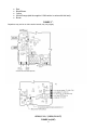
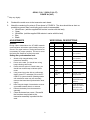
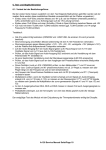
MANUFACTURER OF:
•ANI Systems
•Mobile Data
•Voice Encryption Modules
•Tone Signaling Boards
Manual # 600-1701
March 3,1999
USER'S GUIDE FOR
INSTALLATION AND OPERATION
MODEL ST-025BGP
Mobilecall® Voice Encryption Module
For use in Motorola GP300, GP88, P110, and
P110-5T (European Version) Transceiver
______________________________________________________________________________________
23210 Bernhardt St.
Fax: (510) 781-5454
•
•
Hayward, CA. 94545, U.S.A.
E-Mail [email protected]
•
•
(800) 227-0376
www.selectone.com
TABLE OF CONTENTS
GENERAL.............................................................................................................................................................. 2
SPECIFICATIONS................................................................................................................................................. 2
OPERATION.......................................................................................................................................................... 2
DOUBLE CLICK MODE ...................................................................................................................................... 2
TRANSMIT DELAY.............................................................................................................................................. 2
USER CODE KEYS ............................................................................................................................................... 3
INSTALLION......................................................................................................................................................... 3
FIGURE 1 ............................................................................................................................................................ 3
GP300, P110, **(GP88, P110-5T) FIGURE 2A (UHF) ......................................................................................... 4
GP300, P110, **(GP88, P110-5T) FIGURE 2B (VHF) ......................................................................................... 4
FIGURE 3* - ........................................................................................................................................................ 5
GP300, P110, **(GP88, P110-5T) ........................................................................................................................ 5
FIGURE 4A (UHF)................................................................................................................................................ 5
GP300, P110, **(GP88, P110-5T) FIGURE 4B (VHF).......................................................................................... 6
ADJUSTMENTS .................................................................................................................................................... 6
GENERAL: ............................................................................................................................................................. 6
SETTING THE SYNCHRONIZATION LEVEL: ................................................................................................................ 6
WIRE SIGNAL DESCRIPTIONS ......................................................................................................................... 6
SCHEMATIC ......................................................................................................................................................... 7
COMPONENT LOCATOR ................................................................................................................................... 8
DISCLAIMER .......................................................................................................................................................... 8
WARRANTY POLICY .............................................................................ERROR! BOOKMARK NOT DEFINED.
1
code key. Ciphered reception is automatic; other
units transmitting with the selected code key will be
automatically deciphered. Clear transmissions will
also be received automatically.
GENERAL
The ST-025BGP is an ST-025B voice encryption
device with additional application components and
instructions for use with the Motorola Radius Model
GP300 Transceivers. It is used to secure two way
radio communication systems. The cipher process
uses a proprietary microprocessor controlled digital
scrambling algorithm. Each unit can be programmed
with four User Code Keys, with over 4 billion code
keys to choose from. Special factory set master
code key groups are reserved to provide extra
security for special services. Each master code key
group has over 268 million possible code keys. To
maintain security, code keys are never transmitted.
Audio processing filters provide high quality low
distortion recovered audio.
DOUBLE CLICK MODE
The ST-025B must be programmed for this mode.
This mode of operation is enabled during
programming. The Clear/Ciphered line is connected
to the option 2 switch. The user can toggle between
Clear/Ciphered by operating the switch two times in
rapid succession (Double Clicking). The ST-025B will
then provide a tone output to the radio speaker. A
high frequency beep or series of beeps indicate
subsequent transmissions will be Ciphered. A low
frequency tone for .5 Sec. indicates subsequent
transmissions will be in the Clear (NOT Ciphered).
User Code Keys are selected by operating the same
switch [option 2] four times in rapid succession (Quad
Clicking). Quad Clicking permits switching between
User Code Keys when in the transmit Cipher Mode
(Double Click selection). Each Quad Click
transaction advances the selected User Code Key
one step around a loop of possible selections
(Primary, Alt #1, Alt #2, Alt #3, Primary...). Following
a Quad Click sequence the ST-025B responds with
speaker beeps to indicate the selection position
(Primary: 1 Beep, First Alt: 2 Beeps, Second Alt: 3
Beeps, Third Alt: 4 beeps). When returning to cipher
mode from clear mode, the last used User Code Key
will be selected and indicated with speaker beeps.
Following power-up Cipher operation will select the
Primary User Code Key.
FNote: This manual is intended for use in
place of the manual provided with the
ST-025B.
FNote: The ST-025BGP cannot be used in a radio with
a DTMF keypad option.
SPECIFICATIONS
Specification
Encryption:
Operating Voltage:
Operating Current:
User Code Keys:
Cipher Algorithm:
Synchronization:
Usable Audio Level
Input to Output
Frequency
Temp: Range:
Interface:
Size:
Detail
32 bit algorithm
5.2 Vdc to 16.3 Vdc
< 8mAdc
Greater Than 1012 or 1
Real Time Frequency
Initial and Maintenance
25 mV p-p to 2.0 V p-p
< ± 1 dB
300 Hz to 2600 Hz
0° C to 70° C
18” flying leads terminated
in a 13 pin connector.
0.90” W X 1.50” L X 0.18” H
22.8mm X 38.1mm X4.6mm
Transmit DELAY
All radio systems have an operating delay. This is the
time between PTT activation at a transmitter and
speaker audio being available at the receiving point.
This time may vary considerably from system to
system or even from transmission to transmission.
For reliable cipher operation the ST-025B must wait
for this time period before signaling the beginning of
a ciphered transmission. System delays must be
evaluated and accommodated for with the INITIAL
SYNCHRONIZATION DELAY parameter.
Specifications are subject to change without notice.
FNote:
Operation of radio equipment with encrypted
For many radio operators it is difficult to reliably
know how long to wait before speaking in ciphered
mode. This can cause loss of the beginning of a
message. The ST-025B can be programmed to
accommodate this problem. For cipher transmissions
the ST-025B will provide all the necessary timing and
beep the speaker as a "GO AHEAD" and speak
indication.
speech capability may be government regulated. You are
responsible
for
compliance
with
applicable
radio
regulations regarding operation of this equipment.
OPERATION
Operation is almost transparent to the user. The
user may select any one of 4 previously programmed
code keys. The user then enables or disables the
transmit cipher mode. Once enabled all subsequent
transmissions will be ciphered using the selected
2
Code Keys for each unit. These may be used to
provide different levels of security within a particular
radio
USER CODE KEYS
Of the more than 268 million available code keys,
four may be selected and easily accessed as User
system (officers, sergeants, lieutenants, captains).
accessed via the Selectone Web page on the
Internet at www.selectone.com.
The ST-25 Product manager is launched from the
Select.one directory as ST25.exe. As a default, com
port #1 is used. To select com port #2 use ST25.exe
/2 as the launching command.
Setup and Programming
Other than level setting, all customization is
accomplished with Selectone Product Manager a
Microsoft Windows based program.
During
installation all units MUST be connected to the
Selectone Program Manager. The Microsoft
Windows based program is fully documented with an
on line manual, accessed through the help menu.
The online manual provides advantages in that
corrections and upgrades can be immediately
FNote:
The security of your system depends on the
secrecy of your code keys. For secure operation we
recommend
changing
your
code
keys
often.
INSTALLATION
1.
2.
3.
4.
Program the following for the ST-025B
• Tx Alert on
• Operating mode - double click
• 4 cipher codes - your secret codes
• Install a 33K resistor at R4, R21, R28, & R35
Open the transceiver.
Remove the foam rubber pad from the inside of the front cover.
Use the supplied double-stick foam adhesive tape to mount the ST-025B with the cable assembly
onto the metal case as shown in FIGURE 1.
FIGURE 1
3
5.
6.
Remove the metal case from the transceiver main board by unclipping the four spring clips.
On the back side of the transceiver main board (the side towards the battery pack), remove R455
and R506, see FIGURES 2a and 2b.
Not on
newer
versions
of radios.
GP300, P110, **(GP88, P110-5T)
FIGURE 2a (UHF)
GP300, P110, **(GP88, P110-5T)
FIGURE 2b (VHF)
** May vary slightly
7.
Five wires wrap around the end of the metal case and go to points that are normally covered by
the metal case. Wrap the five wires around the end of the metal case and attach them to the
transceiver main board as shown in FIGURES 3, 4a, and 4b. The wires should pass through the
notch of the case.
4
•
•
•
•
•
Red
Black/Brown
Yellow
White/Orange (add the supplied 1.2M resistor in series with this lead).
Brown
FIGURE 3* -
Capacitors may not be on older version boards, may vary slightly.
GP300, P110, **(GP88, P110-5T)
FIGURE 4a (UHF)
5
GP300, P110, **(GP88, P110-5T)
FIGURE 4b (VHF)
** May vary slightly
8.
9.
Reattach the metal cover to the transceiver main board.
Attach the remaining five wires to P1 as shown in FIGURE 4. The wires should be as short as
possible to prevent them from binding as the radio is reassembled.
• White/Green (add the supplied 24K resistor in series with this lead)
• Green
• White/Blue (add the supplied 30K resistor in series with this lead)
• Blue
• Black
ADJUSTMENTS
WIRE SIGNAL DESCRIPTIONS
General:
Pin #
Signal Name
Wire Color
Signal Description
11
Rx Audio In
Blue
no RF, noise ~1 Vpp
1
Rx Audio Out
White/Blue
no RF, noise ~0.5 Vpp
12
Tx Audio In
Green
Mic audio, ~0.2 Vpp
During cipher transmissions the ST-025B transmits
synchronization information approximately twice per
second. This signal carries no coding information but
is necessary for proper operation. The level is set at
the factory but should be verified in the radio.
Setting the synchronization level:
1.
2.
3.
4.
5.
13
6
7.
Close the transceiver covers. Be careful
that no wires are pinched as the
transceiver assembly is pushed into the
case.
White/Green
Mic audio, ~0.2 Vpp
PTT
Yellow
+5Vdc, PTT released
0Vdc, PTT pressed
3
Positive Supply
Red
Vcc, ~7.5 volts
9
Negative
Black
Ground, 0Vdc
Black/Brown
normally +7Vdc, 0Vdc
Supply
Using a service monitor with an oscilloscope
display, press PTT and adjust R10 on the ST025B for ½ system deviation (Readings made
with a deviation meter may not accurately
measure the intermittent synchronization burst
signal).
Note: Keep the length of transmission as short
as possible because there is no antenna.
Remove the battery from the transceiver
assembly.
Tx Audio Out
(PTT pressed)
Attach a fully charged battery to the
transceiver assembly.
Power on the radio, you should hear a long
beep indicating clear mode.
Double click the option 2 Control button, you
should hear a short beep to indicate cipher
mode.
6.
(PTT pressed)
8
Audio Amp
Enable
4
Alert Tone
during alert tone
White/Orange
normally ground +5 volt
square wave during
alert tone
7
Clear/Cipher
Input
Brown
+5Vdc with Control
button opt 2 released
0Vdc with Control
button opt 2 pressed
6
3 Pole High Pass
C1
.022uF
C2
8
.01uF
R1
R2
200K
200K
R5
9
U1C 10
+
R6
4.3K
180K
C4
2200PF
TL064
C5
2200PF
R3
36K
13
14
U1D 12
+
TL064
C6
2200PF
R9
1.2M
R10
33K
R7
VBias
R8
75K
75K
R12
120K
R11
2.7K
R4
33K
C3
.01uF
+5Vdc
R14
11K
VBias
**MODULATOR**
4
2
VBias
C7
.22uF
1
RX AUDIO OUTPUT
(WHT/BLU)
11
R15
R16
10K
**UPPER SIDEBAND FILTER**
10K
U3
13
U2D
+
12
VBias
R17
10K
13
12
14
X
Z1
Z0
Z
VEE
VSS
16
15
14
R18
100K
C8
2200PF
R19
100K
5
C9
1000PF
7
B
C
INH
A
6
R20
100K
4
7
U1B
+
TL064
C10
120PF
C11
.022uF
8
VDD
10
9
VBias
Y
Y1
Y0
3
5
+5Vdc
4053
X1
X0
1
2
TL064
R22
33K
R21
33K
R13
30K
1
U1A
+
TL064
3
6
11
Placed in series with wire
R24
10K 1T
VBias
Sync Adjust
R26
56K
C12
.1uF
RX AUDIO INPUT
(BLU)
6
11
5
7
U2B
+
TL064
R25
10K
R27
1M
C13
330PF
R29
100K
C14
1000PF
R28
33K
R31
33K
R30
5.6K
R32
5.6K
VBias
U4
24C01
1
C15
.1uF
2
3
** CTCSS BYPASS FILTER **
4
A0
Vcc
A1
Test
A3
SCL
Vss SDL
+5Vdc
9
VBias
10
U2C
+
R44
24K
8
13
TX AUDIO OUTPUT
(WHT/GRN)
TL064
8
7
6
5
**EEPROM**
6
R45
100K
5
C24
4700pF
** SYNC DETECTOR **
7
U7B
+
TL062
R46
100K
8
2
Add Wire
3
R36
33K
R35
33K
R33
10K
+5Vdc
U7A
+
3
C17
330PF
11
Vbias
PTT INPUT
(YEL)
7
6
5
4
3
2
R40
6
RC7
RC6
RC5
RC4
RC3
RC2
RC1
RC0
RA5
RA4
RA3
RA2
RA1
RA0
100K
U6
LP2980
C21
.1UF
GND
CODE SELECT 2/COS
(BLK/ORG)
10
Osc1
Vdd
MCLR
9
Y1
3.58MHZ
Vss
Vss
10
C18
18PF
PTT OUTPUT
(BLK/YEL)
C19
18PF
19
8
R37
10K
8
R42
6.8K
+
VBias
C20
2.2 UF
R43
6.8K
NEGATIVE (-) SUPPLY
(BLK)
20
1
R34
1.3M
28
27
26
25
24
23
22
21
+5Vdc
5
N/C
ON/OFF
Vout
4
Vin
2
1
3
3
RB7
RB6
RB5
RB4
RB3
RB2
RB1
RB0
Osc2
+5Vdc
**REGULATOR**
POSITIVE (+) SUPPLY
(RED)
5
PIC16C62A
18
17
16
15
14
13
12
11
1
U2A
+
TL064
R39
1M
SPK BEEP/RS232/LED
(WHT/ORG)
Q1
MMUN2132
U5
4
2
4
4
Vbias
R38
1K
MONITOR/CLEAR/CIPHERED
(BRN)
+5Vdc
Break Connection
C16
.1uF
7
1
+5Vdc
12
RS232 IN/CODE SELECT 1
(VIO)
TL062
VBias
TX AUDIO INPUT
(GRN)
2
+
C22
2.2 UF
9
SCHEMATIC
7
AMP ENABLE/CODE SELECT 3
(BLK/BRN)
COMPONENT LOCATOR
C24
U6
U7
U5
Q1
U3
R42
C11
R21
C13
C16
R37
R40
C12
R46
R4
R35
R14
R34
U4
C17
R44
C14
R27
R22
R26
R39
R36
+
R45
C9
R7
R31
R38
R32
U2
C20
C21
R3
R17
R15
C7
C10
R16
C15
C18
C19
R43
R25
R30
+
R13
R33
J1
R20
R10
C3
U1
R12
R24
C22
C1
R8
C2
R5
R6
R29
C8
R18
R9
Y1
R19
R1
R2
C4
C5
C6
R11
INSULATED JUMPER WIRE
TO PIN 3 OF U7
R28
TOP SIDE
BOTTOM SIDE
WARRANTY POLICY
All standard Selectone products are guaranteed to meet or exceed published
performance specifications and are warranted against defects in material and
workmanship for a period of five years from the date of purchase. Special
configurations and non-standard systems are warranted for a period of one
year.
If any standard Selectone product fails to operate within the first 90 days from
the date of purchase, Selectone will immediately send out a replacement unit
and will issue full credit, including freight, upon the return of the defective unit(s).
All prepay/C.O.D. customers must return the defective equipment prior to
exchange, otherwise the customer will be required to prepay for the new unit(s)
with credit issued only on the return of the defective equipment.
After 90 days, this warranty is specifically limited to correction of the defects
by factory or replacement of faulty equipment or parts.
All warranty repairs must be performed at the Selectone factory in Hayward,
California. No credit will be given for unauthorized repair work attempted by the
customer. Any unauthorized alterations or modification of the equipment,
damage caused by external sources, or removal or alteration of the serial
number label or date code, will void the warranty. Specifically excluded from this
warranty are batteries, fuses, lamps, and damage caused by lightning, power
surges, or mechanical abuse.
For equipment to be returned to the factory for repair, you must first call and
get an RMA# from Customer Service. The RMA# must be written on the outside
of the package, otherwise receiving will reject the shipment. In addition, a note
must be sent with the packing list briefly describing the nature of the defect.
For special warranty replacement service, of if any other assistance is
required, contact Selectone Customer Service Department at (800) 227-0376,
FAX (510) 781-5454, E-Mail [email protected], or on the WEB at
www.selectone.com.
F NOTE: Export of this product is under
the jurisdiction of the U.S. Department of
Commerce. An Export License is
Require.
Disclaimer
This is the installation procedure for Selectone
equipment based on the best information
available to us at the time of publication.
Selectone assumes no responsibility for the
accuracy of the information or the damage to
equipment resulting from the use of this
procedure.
All repairs and returns are to be sent to:
23210 Bernhardt St
Hayward, CA 94545
Attn: Customer Service
8