1
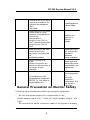
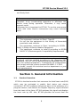
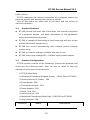
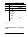
BT-300 Service Manual V2.0 Table of Contents TERMS OF WARRANTY................................................................3 CAUTION.........................................................................................3 HOW TO CONTACT US ….............................................................4 DEFINITION OF WARNING, CAUTION, NOTE.............................6 GENERAL PRECAUTION ON ENVIRONMENT............................7 GENERAL PRECAUTION ON ELECTRIC SAFETY.....................8 SECTION 1. GENERAL INFORMATION .................9 1.1 Product Overview....................................................................9 1.2 Product Features...................................................................10 1.3 Product Configuration..........................................................10 SECTION 2. TECHNICAL DESCRIPTION...................................11 2.2 Main Unit.................................................................................12 1.2. Composition.........................................................................12 2.2. Main Board..........................................................................13 2.2.3Key Board.............................................................................25 2.3Doppler Probe.........................................................................26 2.3.1 Composition.......................................................................27 2.4UC Probe................................................................................27 2.4.1 Composition.......................................................................27 2.4.2 Technical Description.........................................................28 SECTION 3. TROUBLESHOOTING.............................................30 1 BT-300 Service Manual V2.0 3.1 Warning Sign Occasion and Status Checking...................30 Alarm Occasion and Status Checking Up.................................31 3.2 Troubleshooting on the Other Situation.............................31 SECTION 4. MAINTENANCE AND CLEANING..........................33 4.1 Maintenance and Cleaning...................................................33 Caution....................................................................................34 4.2 Regular Inspection................................................................34 SECTION 5. SPECIFICATIONS....................................................35 2 BT-300 Service Manual V2.0 Terms of Warranty - This product is manufactured and examined by strict quality control and inspection system. - Compensation standard concerning repair, replacement and refund of the product complies with “Consumer’s protection law” issued by Economic Planning Dept. - BT-300 is guaranteed by BISTOS Co., Ltd. And its warranty period is two years from the date of purchase. - Warranty repair or replacement will be made by BISTOS Service Center with free of charge during warranty period if properly used under normal condition in accordance with the instructions for use. - In the event of a malfunction or failure during warranty period, customer should inform BISTOS Co., Ltd. of the model name, serial number, date of purchase and explanation of failure about the defective equipment. Caution Federal law restricts this device to sale by or on the order of a physician 3 BT-300 Service Manual V2.0 How to contact us … 4 BT-300 Service Manual V2.0 5 BT-300 Service Manual V2.0 You can contact us the following address and telephone numbers for services and supplies. Oversea Sales Team BISTOS Co., Ltd. Product and Order Inquiries 201, 2F, 239-15, Gasan-Dong, Geumcheon-Gu, Seoul, Korea Tel : +82-2-862-0642 Fax: +82-2-862-0644 Customer Service Team Service Request and Technical Support BISTOS Co., Ltd. 201, 2F, 239-15, Gasan-Dong, Geumcheon-Gu, Seoul, Korea Tel : +82-2-862-0642 Fax: +82-2-862-0644 Our Website & Email address Website: http://www.bistos.co.kr Email: [email protected] Definition of Warning, Caution, Note 6 BT-300 Service Manual V2.0 For a special emphasis on agreement, terms are defined as listed below in operation manual. Users should operate the equipment according to all the Warning and Caution instructions. Manufacturer or Sales agency takes no responsibility for any kind of damage or breakdown that is caused by misuse and failure to maintain the equipment. Warning A Warning indicates a potentially hazardous situation which, if not avoided, could result in death or serious injury. Caution A Caution indicates a potentially hazardous situation which, if not avoided, may result in minor or moderate injury. Note A Note indicates a particular point of information; something on which to focus your attention. General Precaution on Environment Do not keep or operate the equipment under the environment listed below. 7 BT-300 Service Manual V2.0 Avoid placing in an area exposed to moisture. Do not touch the equipment with wet hand. Avoid exposure to direct sunlight Avoid placing in an area where there is a high variation of temperature. Operating temperature ranges from 10°C to 40°C. Operating humidity ranges from 30% to 85%. Avoid in the vicinity of Electric heater Avoid placing in an area where there is an excessive humidity rise or ventilation problem. Avoid placing in an area where there is an excessive shock or vibration. Avoid placing in an area where chemicals are stored or where there is in danger of gas leakage. Avoid dust and especially metal material into the equipment. Do not disjoint or disassemble the equipment. BISTOS Co., Ltd. takes no responsibility of it Power off when the equipment is not fully installed. Otherwise, the equipment could be General Precaution on Electric Safety Check the items listed below before operating the equipment. - Be sure that power supply line is appropriate to use. (Power Adaptor Input: 100 ~ 250V AC, Power Adaptor Output: 16V, 2.8A). - Be sure that the entire connection cable of the system is properly 8 BT-300 Service Manual V2.0 and firmly fixed. Note The equipment should not be placed in the vicinity of electric generator, X-ray, broadcasting apparatus to eliminate the electric noise during operation. Otherwise, it may cause incorrect result. Self-power line is important for BT-300. To use the same power source with other electric instruments may cause incorrect result. Note BT-300 is classified as listed below; - This equipment conforms to Class I, Type-BF. - Do not use the equipment in the vicinity of flammable anesthetics and solvents. The equipment conforms to Class I according to IEC/EN 60601-1 (Safety of Electric Medical Equipment) - This equipment conforms to Level B according to IEC/EN 60601-1-2 (Electromagnetic Compatibility Requirements) Note Accessory equipment connected to the analog and digital interfaces must be certified according to the respective IEC standards ( e.g. IEC 950 for data processing equipment and IEC 601-1 for medical equipment ). Furthermore all configurations shall comply with the system standard EN 60601-1-1:1993. If in doubt, consult the technical service department or your local representative. Section 1. General Information 1.1 Product Overview BT-300 is the fetal monitor that measures the fetal heart rate(FHR) which may be evaluated to predict fetal status and uterine contraction. BT-300 irradiates ultrasound wave to the abdomen of a pregnant woman, and detects the Doppler frequency signal reflected from the heart of the fetus. BT-300 analyzes this signal and displays the heart rate by LED. Also, BT-300 provides the sound from the 9 BT-300 Service Manual V2.0 heart of fetus. BT-300 measures the uterine contraction of a pregnant woman by pressure sensors and displays the numerical values. And BT-300 prints the heart rate of the fetus and the values of uterine contraction. 1.2 Product Features BT-300 records the heart rate of the fetus, the uterine contraction of a pregnant woman, and basic information of the equipment with a provided thermal printer. BT-300 is capable of Monitoring of fetal heart rate with one or two pulsed Ultrasound Transducer(s). BT-300 can record automatically with thermal printer through printer setup. BT-300 is compact and light, potable and easy to use. BT-300 uses a free voltage(100 – 240VAC input) power adaptor. 1.3 Product Configuration BT-300 system consists of the followings. Unpack the package and check out the following items. Also, be sure to check to see any damage of main body and accessories ① BT-300 Main Body ② Ultrasound Transducer(Doppler Probe) - 2 EA(1 EA for BT-300S) ③ Tocotransducer(UC Probe) - 1EA ④ Event Marker -1EA ⑤ Thermal Print Paper - 2EA ⑥ Power Adaptor -1EA ⑦ Power Cord -1EA ⑧ Ultrasound Gel -1EA ⑨ Abdominal Transducer(Probe) Belt -3 EA(2 EA for BT-300S) ⑩ User’s Manual -1EA Contents Name Description 10 BT-300 Service Manual V2.0 BT-300 Main Body Main body of BT-300 (2-year Warranty) Doppler Probe Ultrasound Transducer for Measuring FHR UC Probe Pressure Sensor(Tocotransducer) for Measuring Uterine contraction Event Marker Used for a specific event(for example, fetal Movement) Z-folded type Paper Z-folder type thermal Paper Probe Belt Used for Holding Doppler Probe and/or UC Probe Power Adaptor Adaptor for transform AC Power to DC 16V Power Cord AC Power cord Ultrasound Gel Ultrasonic coupling gel Section 2. Technical Description 2.1 General BT-300 is capable of monitoring fetal heart rate and maternal uterine contractions. Simultaneous trends of fetal heart rates (FHR) and uterine activity (UA) are plotted by the built-in chart recorder. FHR and UA are displayed continuously at numeric display on the front panel. Measuring fetal heart rate is using 1MHz ultrasound wave which transmits the burst pulse to the 7 ultrasound sensors about 3.47KHz periodically. This wave is reflected to the part of different medium. 11 BT-300 Service Manual V2.0 Particularly, the reflection wave is shifted from moving targets like heart, blood, etc. This phenomenon is a Doppler effect. This reflected signal is converted to electrical signal and it can get some useful information by many other processes. Also, BT-300 measures the uterine contraction of a pregnant woman by pressure sensors and displays waveform by means of numerical values. This waveform informs the period and magnitude of the uterine contraction. DSP(digital signal processor) calculates the fetal heart rate and uterine contraction, and transmits them to CPU by serial communication. CPU displays these values to the 7-segment, records on the thermal paper and transmits to serial port for central monitoring system. CPU performs these operations by input of key. Refer to the operator’s manual for more detailed operations. 2.2 1.2. Main Unit Composition ① 12 BT-300 Service Manual V2.0 ② ③ ① Key Board ② Print Engine ③ Main Board 2.2. Main Board Circuit Diagram < Analog Part > 13 BT-300 Service Manual V2.0 D1 D O P 1_I R1 D O P 1_Q AVP12 R2 AV P12 C2 R3 R5 Q1 C3 R4 11 C 28 D2 11 R 15 5 C 14 R 11 11 C 13 7 13 12 C 15 4 C 10 U 3D TL064 TL064 C 19 U 1C 2 14 R 19 11 10 C27 TL 06 4 1 4 4 AVP5 C 22 3 C 17 R 22 AVP5 R 23 TL064 9 U 3A 11 11 4 R 12 R18 U 1B 6 R21 C 170 R 31 C6 R 14 4 C 18 D G 212 C 26 R28 3 AV P12 AVP5 R 29 R 27 D3 TL 064 1 AVP5 AVP12 8 C 23 C 25 AVP5 R 165 4 R 26 R 25 R 24 C9 R 10 U 1A 2 C12 AVP5 C21 Q5 C 24 AVP5 13 V+ 4 V- 12 VC C 5 GND S1 S2 S3 S4 R8 + C 20 R 30 AVP 12 - C 16 Q4 D O P 1 _ ID 3 14 11 6 R7 14 + R 17 1 16 9 8 + L M B 0 5 0 9 -6 P R 16 R 20 IN 1 IN 2 IN 3 IN 4 + C11 D1 D2 D3 D4 - 2 15 10 7 R13 L2 12 C5 AVP 12 TL064 13 C 169 U2 + AVP 12 C7 L1 R6 - N1 N2 N3 U 1D Q3 + J1 R9 AVP5 - C4 AVP 12 1 2 3 5 6 8 C8 D O P 1_ P Q2 - + - C1 R 32 AVP5 D4 R36 R 42 5 D7 4 TL064 9 10 AVP5 8 4 C36 C 35 R 51 11 TL 064 R57 C 40 TL064 6 R 59 + 4 C 41 R58 5 C 42 R 62 4 R 55 AVP5 R 67 R 64 C 45 1 2 3 5 6 8 D O P 2_P VO L2_0 VO L2_1 J4 2 4 6 8 C46 R 68 3 U 6C 9 10 A B C 6 TL064 8 C 43 D 1_R EF IN H 16 7 C 44 O /I VDD VEE D O P1_S C D 40 51B AVP5 2 4 6 8 1 3 5 7 R 53 I /O 0 I /O 1 I /O 2 I /O 3 I /O 4 I /O 5 I /O 6 I /O 7 11 10 9 V O L1_ 0 V O L1_ 1 V O L1_ 2 AVP12 R 66 AVP 12 J3 A N AL_C O N R 70 R 69 R71 IV P 1 6 D O P1_S R 73 U 7A TL064 R75 R 76 1 C48 + C 47 U 7D 11 11 - 3 13 12 TL06 4 U8 C 50 14 J6 1 C 51 4 2 C52 + 1 2 2 4 6 8 4 2 + R 74 D O P2_S D O P 2_S D O P 2_H R AVP5 C 49 - VO L2_2 D O P 2_Q D O P 2_I D O P 2 _ ID R 72 + TR AN S D U C ER 1 3 5 7 L M B 0 5 0 9 -6 P 5 N1 N2 N3 R 60 7 D 1_R EF R 63 S TIM U LA TO R J2 R 56 U6B R 61 1 D9 4 C 39 13 14 15 12 1 5 2 4 11 11 3 + 2 14 - 12 C 38 + TL064 13 R 65 U 6A - D8 U5 R 52 R 54 U 6D 11 R 50 4 4 R 49 + + 4 AVP5 AVP12 R 48 AVP5 D O P1_H R C 34 AVP5 C 37 R 44 7 - - AVP5 U 4C TL06 4 6 R 47 R 46 U 4B R 43 4 8 TL0 64 1 4 3 11 2 14 11 11 11 11 11 12 AVP5 + 10 TL064 - 9 + 5 R 45 TL064 13 U 3C TL0 64 7 - 6 C 30 + C 33 R 38 R39 U 4A - R 40 U3B C 32 R 37 D6 U 4D + R 35 - R 34 + C 29 D5 R 41 - R 33 C 31 AVP5 1 3 5 7 C 54 R 77 AV P12 TD A 2030 R 78 5 2 6 7 -2 R80 U 7C AVP12 11 AVP 12 TL 06 4 9 - 10 C55 R82 C 61 UC + C 58 R 81 C 56 + C 57 PW M R83 4 L M B 0 5 0 9 -6 P 8 + N1 N2 N3 C 53 R 79 3 A N A L_ S IG 1 2 3 5 6 8 4 AVP5 J5 J7 C 62 R 84 C 63 U C _ ID U 9 LM 7812 1 OUT IN C 65 3 AV P12 AVP12 C 59 GND + 78L05 3 + C 60 VO VI 1 IV P 1 6 G7 G6 G1 G2 G3 G4 G5 1 1 1 1 1 1 1 H T J - 0 3 5 -1 0 MAR K C 64 2 1 2 GND AVP5 J8 2 U 10 (MARK JACK) T it le S iz e C D ate: < Digital Part > 14 B T 3 0 0 D / S A N A L O G C I R C U I T b y R & D d e p t . b is t o s . c o . lt d . D ocum ent N um ber P C B -1 0 0 -M A I N - P 0 3 월 요 일 , 10월 20, 2003 Rev C S hee t 1 of 2 BT-300 Service Manual V2.0 DVP5 C 66 PD0 PD1 PD2 PD3 PD4 PD5 PD6 PD7 7 4H C 0 4 TPH _C K 8 TPH _D I 7 14 4 5 6 9 /S E G V _ W R 2 3 4 5 6 7 8 9 11 IN I _ E N 1 74H C 04 D1 D2 D3 D4 D5 D6 D7 D8 Q1 Q2 Q3 Q4 Q5 Q6 Q7 Q8 C LK VC C OE GND 19 18 17 16 15 14 13 12 SEG_V1 SEG_V2 SEG_V3 SEG_V4 SEG_V5 SEG_V6 SEG_V7 DU AL R85 R86 R87 R88 R89 R90 R91 20 V 3 V1 3 V2 3 V3 3 V4 3 V5 3 V6 3 V7 3 V8 3 V9 4 V0 4 V1 4 V2 4 V3 4 V4 4 V5 4 V6 4 V7 4 V8 4 V9 5 V0 5 V1 5 V2 5 V3 5 V4 5 V5 5 V6 5 V7 5 V8 5 V9 6 0 1 1 11 1 11 1 1 11 1 11 1 11 1 1 11 1 11 1 11 1 1 1 U 22B 3 7 14 2 V 6 V1 6 V2 6 V3 6 V4 6 V5 6 V6 6 V7 6 V8 6 V9 7 V0 7 V1 7 V2 7 V3 7 V4 7 V5 7 V6 7 V7 7 V8 7 V9 8 V0 8 V1 8 V2 8 V3 8 V4 8 V5 8 V6 8 V7 8 V8 8 V9 9 0 DVP5 10 1 1 11 1 11 1 1 11 1 11 1 11 1 1 11 1 11 1 11 1 1 1 74H C 04 14 14 U 11 U 2 2A 1 C 6 7 C 6 8 C 6 9 C 7 0 C 7 1 C 72 C 73 V 9 V1 9 V2 9 V3 9 V4 9 V5 9 V6 9 V7 9 V8 9 V9 1 V0 10 V0 1 V0 21 V0 13 V0 41 V0 51 V0 61 V0 71 V0 81 V0 91 V1 10 V1 1 V1 21 V1 31 V1 41 V1 51 V1 16 V1 71 V1 18 V1 91 2 0 C 74 U 22D 74H C 574 U 13 PD0 PD1 PD2 PD3 PD4 PD5 PD6 PD7 D VP5 U 43 R TC _/C S R TC _AS R TC _D S R 96 D V P 1 .8 D V P 3 .3 128 111 1 06 76 70 57 45 00 34 31 4 Vss Vss VV ss ss Vss Vss VV ss ss Vss VV ss ss M M 1 07 5 C 100 J 11 D VP5 1 2 3 4 5 6 7 VPP 4 5 6 7 8 9 10 11 12 1 18 U 1 8 ,24 P D VP5 PD7 PD6 /K E Y D _ R D /I D D _ R D 2 D U A L / S IN G L E /S E G E _W R 11 IN I _ E N DVP5 C 1 11 U 12B R S_D SP PD0 PD1 PD2 PD3 PD4 PD5 PD6 PD7 R 10 4 R T C _ /C S R TC _AS R T C _ R /W R TC _D S /LE D D _ W R 74H C 04 PD0 PD1 PD2 PD3 PD4 PD5 PD6 PD7 U 1 2D 1 D VP5 7 5 14 3 DVP5 4 VC C 4 C1+ VDD C1- V+ NC 1 P1 9 D V P 3.3 3 OUT GND 2 N1 N2 1 5 .7 6 M H z O S C (5 V ) C 133 C2+ V- D -S U B 9 P 1 6 2 7 3 8 4 9 5 5 R 148 R 149 C2- GND 14 1 3 T1 O U T 7 R 1 IN 8 T2 O U T R 2 IN C 145 TX RX /V O LD _W R 11 1 PD0 PD1 PD2 PD3 PD4 PD5 PD6 PD7 2 4K 1 U 4 0D 1M 2 13 11 DVP5 74H C 04 12 74 H C 08 /P R N C _W R U 3 9 ,1 4 P U 39 B 74H C 08 4 2K 3 C 163 5 6 Q Q 6 8 10 8 9 2K 1M 11 12 D U 41A 3 AN A_R S 74 H C 0 8 C LK C 159 D 11 1 C 157 U 37B D O P2_I 6 U 3 4,1 4 P 1 C 161 1 74H C 08 13 10 8 G ATE2 11 12 9 V 1 V2 1 V2 12 V2 31 V2 14 V2 15 V2 16 V2 71 V2 81 V2 19 V3 01 3 1 C 118 Q1 Q2 Q3 Q4 Q5 Q6 Q7 Q8 C LK VC C OE GND 19 18 17 16 15 14 13 12 R 127 C 124 SEGE6 C 126 Q12 V O L 1 _0 V O L 1 _1 V O L 1 _2 V O L 2 _0 V O L 2 _1 V O L 2 _2 G ATE1 G ATE2 20 C 128 R 130 C 130 19 18 17 16 15 14 13 12 MO TO R _C K0 MO TO R _C K1 MO TO R _C K2 MO TO R _C K3 STR O BE0 STR O BE1 R 132 R 1 33 R 13 4 R 135 R 136 R 137 4.7K 4 .7K 4 .7 K 4 .7 K R 138 SEGE7 Q13 C 129 DVP5 10 R 131 DVP5 Q1 Q2 Q3 Q4 Q5 Q6 Q7 Q8 C LK VC C OE C 131 104 J12 D1 D2 D3 D4 D5 D6 D7 D8 GND U 28 3 6 B1 11 B2 14 B3 B4 DVP5 R 143 MCK0 MCK1 MCK2 MCK3 2 C1 7 C2 9 C 3 16 C4 PVP24 1 K1&4 8 K2&3 R 144 1 2 3 4 5 6 20 PVP24 IV P 16 J9 C 138 6P DVP5 T D 6 20 6 4 A F 2 3 4 5 6 7 8 9 A0 A1 A2 A3 A4 A5 A6 A7 C 142 DVP5 J14 B0 B1 B2 B3 B4 B5 B6 B7 1 2 3 4 5 6 7 8 9 10 11 12 13 14 15 C 141 10 18 17 16 15 14 13 12 11 1 20 1 9 D IR V C C 1 0 OE GND PAPER D OOR 1 2 D O P 1 _ ID D O P 2 _ ID U C _ID 5 2 6 7-2 STR OBE0 STR OBE1 T P H _C K /T P H _ L E T P H _D I R 153 DVP5 S TIM U L A T O R R 154 R 155 R 156 R 15 7 15P R 1 58 C 148 DVP5 J13 U 22E J17 U 22 F 10 11 DVP5 12 13 1 2 3 74 H C 04 A 13 R 161 R 1 6 0 5 2 6 7 -3 74 H C 0 4 C 155 C LR 12 R 1 59 A 1 LED _H 1G LED _H 2G L E D _ R E C /Z O O M LE D _IN F O SEG_V1 SEG_V3 SEG_V5 SEG_V7 V O L _ D N 1 /V O L _ U P V O L _ D N 2 /V O L _ D N U C _R E F SEGE0 SEGE2 SEGE4 SEGE6 SEG_A SEG_C SEG_E SEG_G 1 3 5 7 9 11 13 15 17 19 21 23 25 27 29 31 33 35 37 39 2 4 6 8 10 12 14 16 18 20 22 24 26 28 30 32 34 36 38 40 LED _H 1R LED _H 2R L E D _ A L M /R E C LED _ALM SEG _V2 SEG _V4 SEG _V6 V O L _ U P 1 /A L M VO L_U P2 R E C /Z O O M A L M /R E C SEGE1 SEGE3 SEGE5 SEGE7 SEG _B SEG _D SEG _F C LR C 162 2 H E A D E R 20X2 4K U 34B 9 8 Q Q D C LK 74H C 08 DVP5 DVP5 DUAL 16K 8K 7 4H C 7 4 74 H C 08 U 38A 74H C 393 3 4 QA 5 QB 6 QC QD 3 U 3 7D U 37C D O P2_Q 2 1 C LR 4 PRE 4 L M 1 1 1 7 M P X- 1 .8 C 123 C 125 D1 D2 D3 D4 D5 D6 D7 D8 2 DVP5 D C LK DVP5 5 SEGE5 Q11 C 120 PAPER C LR 7 U 34A 5 6 Q Q 74H C 08 R 126 MARK C 11 7 C 11 9 7 + V IN VOUT 5 2 G N D /A D J C 160 DVP5 1 U 3 7 ,1 4 P SW 2 3 C 115 1 5 .97 4 4 M /A N A _R S 2 D O P2_P GND L5 + C 15 6 U 37A FB 3 4 10 1 3 C 116 DVP5 U 33B 74H C 393 11 10 Q A 9 QB 8 QC QD U 39E 74H C 04 74H C 74 12 11 13 C LR 10 PRE 2K 1M U 38B 74H C 393 11 10 Q A 9 QB 8 QC QD A C LR 13 12 AN A_R S DVP5 DUAL 7 1 11 1 11 1 11 1 1 C 1 58 IN U35 L M 2 5 7 6 S -5 . 0 DVP5 U 36 2 4 OUT 4 1 1M 74H C 08 D V P 1.8 A 2 9 Q 8 Q 13 10 C LR PRE DVP5 74 H C 08 SEGE4 Q10 DVP5 C 14 9 U 33A 74H C 393 3 4 QA 5 QB 6 QC QD 7 12 G ATE1 11 R X_Q 9 1 U 42B 9 8 16K 7 4H C 0 8 14 D O P1_Q V O L _ U P 1 /A L M V O L _ D N 1 /V O L _ U P VOL_U P2 V O L _ D N 2 /V O L _ D N R E C /Z O O M U C _R EF A L M /R E C R 114 R 116 R 117 R 118 R 120 R 121 R 122 R 125 14 12 74H C 04 13 J 16 5 2 6 7-2 18 17 16 15 14 13 12 11 VCC C 1 52 C 151 L M 1 1 1 7 M P X- 3 .3 B0 B1 B2 B3 B4 B5 B6 B7 VCC 13 74 H C 0 8 R X_I 10 23 + C 15 0 2 1 + G N D /A D J C 1 53 10 4 A0 A1 A2 A3 A4 A5 A6 A7 8K GND U 41D 11 DVP5 U 4 2 ,1 4 P U 3 2D /I D D _ R D 14 7 4 H C 08 C 1 54 U 32C C 113 R 115 74H C 245 U 41C 5 74H C 08 C 165 GND J15 H T J - 0 2 0 -0 4 SEGE3 Q9 14 1 R 113 C 1 0 5 C 1 0 6 C 1 0 7 C 1 0 8 C 1 0 9 C 11 0 C 16 7 C 1 68 VCC L4 3 DVP5 U 4 1 ,1 4 P GND GND D VP5 U 3 2 ,14 P 3 IN 4K U 39 D C 166 2 4 OUT 4 16 K 4 74H C 08 74H C 74 74H C 08 4 5 6 /A N A _ R S 9 U 32B D V P 3.3 3 3 6 SEGE2 C 104 C 112 VCC 8 U 41 B 1 C LR 4 PRE 10 2 D O P1_I C LK 2 GND R X_Q D 11 2 1 SW V IN 74H C 04 U 4 0C + C 147 R 108 Q8 DVP5 10 U 30 PD0 PD1 PD2 PD3 PD4 PD5 PD6 PD7 D VP5 U 42A 5 C 164 1 20 C 102 74H C 574 1M 7 4 H C 08 U 39C U 32A 1 5 6 U 29 PQ 2C F1 2 3 4 5 6 7 8 9 11 IN I _ E N DVP5 U 4 0 ,1 4 P D O P1_P GND U 27 U 40 A 4 OE LED _H 1G LED _H 1R LED _H 2G LED _H 2R L E D _ R E C /Z O O M L E D _ A L M /R E C L E D _ IN F O L E D _ A LM R 103 R 105 R 106 R 107 R 109 R 110 R 168 R 169 74H C 574 1 IV P 1 6 2 3 4 5 6 7 8 9 (FEMALE) R 151 C LK VC C 19 18 17 16 15 14 13 12 U 24 PD0 PD1 PD2 PD3 PD4 PD5 PD6 PD7 15 11 T1IN 1 2 R 1OU T 10 T2IN 9 R 2OU T 1 U 31 2 3 4 5 6 7 8 9 M A X 2 3 2 C S E ( S MD ) C 146 L3 R 152 SEGE1 Q1 Q2 Q3 Q4 Q5 Q6 Q7 Q8 74H C 245 C 12 7 U 39 A Vc R 102 C 1 71 6 3 FB SEGE0 C97 C 101 C 121 74H C 04 5 R 100 10 Q7 D1 D2 D3 D4 D5 D6 D7 D8 IN I _ E N 8 C 14 0 4 C 144 1 C 137 2 C 13 9 AD C _C K AD C _R AD C _X AD C _C S R 150 GND Q6 DVP5 1 20 1 9 D IR V C C 1 0 OE GND /K E Y D _R D 74H C 04 16 C 13 6 C 122 104 R X_I 2 OE D VP5 20 74H C 574 R 124 U 26 U 12C R 129 2 3 4 5 6 7 8 9 11 IN I _ E N D V P 3.3 VCC DVP5 C 143 + C LK VC C 19 18 17 16 15 14 13 12 U 19 D VP5 R 119 3 U 4 0B D10 Q1 Q2 Q3 Q4 Q5 Q6 Q7 Q8 DVP5 AD0 19 A D 1 IR Q 23 AD 2 SQ W 24 AD 3 24 AD4 AD5 13 AD 6 C S 14 AD 7 AS 15 G N D R /W 17 MOT DS RST D S 1 2C 88 7 M C P 3 2 0 4 -B I/ S L P V P 24 1 D1 D2 D3 D4 D5 D6 D7 D8 U 21 + R 14 5 R 1 46 R 1 4 7 1 P IC D / L 4 129 19 22 7 62 15 85 17 13 25 24 22 23 21 12 90 67 66 65 64 63 61 32 31 23 09 28 22 76 UC 14 13 12 11 10 9 8 CH0 VDD CH1 VREF CH2 AGND CH3 C LK NC DOUT NC D IN D G N D C S /S H D N DVP5 J1 8 2 3 4 5 6 7 8 9 P D [ 0 .. 7 ] C 1 34 U 25 1 2 3 4 5 6 7 R 142 U 15 PD0 PD1 PD2 PD3 PD4 PD5 PD6 PD7 G2 G1 R 112 74 H C 0 4 D V P 3 .3 D V P 3 .3 D O P2_H R C 8 7 C 8 8 C 8 9 C 9 0 C 9 1 C 92 C 93 10 18 17 IF _ S D O IF _ S D I 51 77 78 79 82 93 94 96 97 98 1 5 .9 7 4 4 M R 14 0 DVP5 20 7 R 111 1 R 16 2 C 13 2 GND 14 U 12A 2 IF _ S C K C 13 5 R 141 OE SEG _A SEG _B SEG _C SEG _D SEG _E SEG _F SEG _G R92 R93 R94 R95 R97 R98 R99 74H C 574 PD0 PD1 PD2 PD3 PD4 PD5 PD6 PD7 D V P 3.3 C 1 03 AD C_R AD C_CK AD C_CS AD C_X U 23 R 139 C LK VC C 19 18 17 16 15 14 13 12 C 94 R 164 U18 41 43 45 48 53 59 42 44 47 49 54 60 74H C 04 D O P1_H R Q1 Q2 Q3 Q4 Q5 Q6 Q7 Q8 74H C 574 P IC 1 6 C 7 7 /T Q F P R 123 D V P 3.3 1 C 98 S S T3 9 V F 51 2 R 128 /S E G V _ W R 11 D1 D2 D3 D4 D5 D6 D7 D8 7 H IN T / T O U T 1 C LK M D 1 C LK M D 2 C LK M D 3 TO U T0 Vss C LK O U T X1 C L K IN / X 2 RS 25 26 27 /S E G D _ W R C 99 14 TM S 3 2 0 V C5 4 0 2 A0 A1 A2 A3 A4 A5 A6 A7 A8 A9 A10 A11 A12 A13 A14 A15 A16 A17 A18 A19 R 1 01 /S E G D _ W R /S E G E _ W R /L E D D _ W R /K E Y D _ R D /V O L D _ W R /P R N C _ W R /I D D _ R D /T P H _ L E 7 32 16 VC C GND C 114 13 1 13 2 13 3 13 4 13 6 13 7 13 8 13 9 14 0 14 1 5 7 8 9 10 11 10 5 10 7 10 8 10 9 DVP5 P IC D /L R S T DVP5 38 39 40 41 2 3 4 5 PW M IF _S C K IF _S D I IF _S D O TX RX 2 3 4 5 6 7 8 9 14 D V P 3 .3 12 11 10 9 8 7 6 5 27 26 23 25 4 28 29 3 2 1 30 22 24 31 C 96 7 A0 A1 A2 A3 A4 A5 A6 A7 A8 A9 A10 A11 A12 A13 A14 A15 A16 1 30 CE OE WE C95 2 4 R T C _ R /W R S _D S P 14 D0 D1 D2 D3 D4 D5 D6 D7 BC LKR 0 BFSR0 BD R0 B C LK X0 B F S X0 B D X0 BC LKR 1 BFSR1 BD R1 B C LK X1 B F S X1 B D X1 58 69 81 95 1 20 1 24 1 35 6 39 46 1 3 6 13 14 15 17 18 19 20 21 HD0 HD1 HD2 HD3 HD4 HD5 HD6 HD7 H C N TL0 H C N TL1 VPP 1 8 2 TC R ESET 7 3 RESET Vs 6 4 CK RCT 5 GND VCC 1 5 .9 7 4 4 M 7 U 20 D0 D1 D2 D3 D4 D5 D6 D7 D V D D : 3 .3 V U 17 HDS2 HH DP SIE 1N A H B IL HH RR D/WY HCS HAS IO S T R B M STR B R /W IS DS PS READY IN T 3 INI N TT 21 IN T 0 INA MC I K M P /M C B IO HI A OQ L D H OLD A MX FS C D [ 0 .. 7 ] C V D D : 1 .8 V D0 D1 D2 D3 D4 D5 D6 D7 D8 D9 D 10 D 11 D 12 D 13 D 14 D 15 J10 32 35 36 37 42 43 44 1 14 89 88 87 86 85 88 43 11 24 25 91 68 15 26 11 13 02 75 53 63 4 CC VV DD DD CVD D CVDD CVDD CVD D DVDD D VDD DVDD DVDD DD VV DD DD TM S TCK T R S TT D I TDO E M U 1 /O F FE M U 0 TMS320VC 5402 99 10 0 10 1 10 2 10 3 10 4 11 3 11 4 11 5 11 6 11 7 11 8 11 9 12 1 12 2 12 3 19 R C 0 / T 1 O S O /T 1 C L K 2 0 R A 0 /A N 0 R C 1 / T 1 O S I/ C C P 2 2 1 R A 1 /A N 1 R C 2/C C P 1 2 2 R A 2 /A N 2 R C 3 /S C K / S C L 2 3 R A 3 /A N 3 / R E F R C 4 / S D I/ S D A 2 4 R A 4 /T 0 C L K R A 5 /A N 4 / S S R C 5/S D O R C 6 /TX/C K 8 R B 0 /I N T R C 7 /R X/ D T 9 10 R B1 R D 0 /P S P 0 11 R B2 R D 1 /P S P 1 14 R B3 R D 2 /P S P 2 15 R B4 R B 5 R D 3 /P S P 3 16 R D 4 /P S P 4 17 R B6 R B7 R D 5 /P S P 5 R D 6 /P S P 6 30 R D 7 /P S P 7 3 1 O S C 1 /C L K O S C 2 /C L K O U T R E 0 /R D / A N 5 18 M C L R /V P P R E 1 /W R /A N 6 R E 2 /C S / A N 7 7 28 V D D VDD PD0 PD1 PD2 PD3 PD4 PD5 PD6 PD7 U 16 D0 D1 D2 D3 D4 D5 D6 D7 1 1 11 1 11 1 1 11 1 11 1 11 1 1 11 1 11 1 11 1 1 1 74H C 04 7 7 U 2 2C C 7 5 C 7 6 C 7 7 C 7 8 C 7 9 C 8 0 C 81 C 8 2 C 8 3 C 8 4 C 8 5 C 8 6 T it le 7 4H C 7 4 B T 3 0 0 D /S D I G IT A L C IR C U IT d e s i g n e d b y B IS T O S R & D D e p t. S iz e D D a te : D o c um e nt N u m b e r P C B -1 0 0 -M A IN - P 0 3 수 요 일 , 1 0 월 22 , 2 0 0 3 R ev C S h e et 2 of 2 Technical Description 1 Doppler signal generation circuit The burst signal drives the ultrasound sensor using by Q1 ~ 15 BT-300 Service Manual V2.0 Q3. The L-C impedance matching circuit is used to match the received ultrasound signal and the signal is amplified about 40 dB at Q5. U2 demodulates by 1MHz to get the Doppler signal and the most adequate signals are abstracted through the 4 stages filter. BT-300 uses the 1MHz ultrasound, so the Doppler frequency is low frequency about 100 ~ 200Hz. The OP Amps (U6A, U6D) perform the frequency doubling by full-wave rectifier to hear clearly when user hears the fetal heart signal. After using the amplifier and LPF, this signal is adjusted the volume (U5, 8 steps) and transferred to audio amplifier (U8). The other rectifier circuit (U4A, U4D) is used to calculate the heart rate, this signal is amplified and used LPF for envelope detection. And adjust the DC level to fit in the input level of U25, A/D converter (0 ~ 3.3V). 2 Sound output circuit The signal of Doppler (DOP1_S, DOP2_S), alarm and information are summed in U7A. The signal for alarm(bee bee bee) and information(ding~ dong~) is PWM signal generated from U43. This signal is converted to be able to hear using RC low pass filter. This signal and Doppler signal are integrated and output to speaker by audio amplifier (U8). ③ A/D converter & DSP circuit MCP3204(U28) A/D converter is possible to convert to 4 channels and converts each signal DOP_1HR, DOP2_HR, UC to 12 bits digital signal by 200Hz periodically. The range of analog input signal of this A/D converter must be in 0 ~ +3.3V. The converted digital signal is transmitted to DSP(U16) by serial and calculated an useful value using many signal processing techniques. DSP is TMS320VC5402 by TI company and the fetal heart rate is calculated at 0.25 second using autocorrelation algorithm. The output is transmitted to CPU to display and record. ④ TX burst pulse generation circuit U33, U34, U37~42 generate the burst signal for driving the ultrasound sensor and control signal for demodulation. The timing diagram is below. < Timing Diagram > 3.47KHz 16 BT-300 Service Manual V2.0 Tx Receive Time DOP1_P DOP1_I,Q DOP2_P DOP2_I,Q 128 usec 32 usec 128 usec ⑤ CPU circuit CPU(U43) is PIC16F77, when it has malfunction, CPU resets itself using MM1075(U17) watch-dog IC. FHR and UA are displayed on the 7-segment and signal quality is displayed on the LED. Thermal print is operated +24V. CPU controls the stepping motor and TPH to record the calculated data on the thermal paper. Door open or paper out is recognized by sensor. If that situation happens during recording, then CPU stops recording and displays “See Prn” on the display panel. Time and date are calculated automatically at the DS12C887(U18). CPU reads the value and records on the recording paper. Each key is recognized by CPU which performs each operation. Connection A. Doppler Probe Connector 17 BT-300 Service Manual V2.0 S T IM U L A T O R AVP12 J1 N 1 N 2 N 3 AVP12 1 2 3 5 6 8 J2 S IG N A L N 1 N 2 N 3 L M B 0 5 0 9 -6 P 1 2 3 5 6 8 S IG N A L L M B 0 5 0 9 -6 P D O P 1 _ ID D O P 2 _ ID Pin 1 I/O I Description Acoustic stimulator enable signal 2 3 5 6 Name Stimulat or GND AVP12 GND Signal O I/O 8 DOP_ID I Ground +12V power Ground Transmitting and signal Identity signal receiving B. UC Probe Connector J7 N 1 N 2 N 3 1 2 3 5 6 8 AVP12 S IG N A L U C _ ID L M B 0 5 0 9 -6 P Pin 1 2 3 5 6 8 Name I/O NC GND Ground AVP12 O +12V power Signal I UC out signal NC UC_ID I Identity signal C. Mark Jack Connection 18 Description ultrasound BT-300 Service Manual V2.0 J6 S IG N A L 1 2 5 2 6 7 -2 Pin 1 2 Name Signal GND I/O I - Description Mark enable signal Ground D. Doppler 2 control signal (only BT-300 dual) D O P2_P VO L2_0 VO L2_1 D O P2_S D O P2_H R AVP5 2 4 6 8 2 4 6 8 J3 J5 AN AL_C O N A N A L _ S IG 1 3 5 7 1 3 5 7 1 3 5 7 S IG N A L 2 4 6 8 J4 TR AN S D U C ER VO L2_2 D O P2_Q D O P2_I Name Signal DOP2_P VOL2_0 VOL2_1 VOL2_2 DOP2_Q DOP2_I DOP2_S DOP2_HR AVP5 AVP12 AVP12 Description Transmitting and receiving ultrasound signal Digital pulse for transmitting Volume control signal 0 Volume control signal 1 Volume control signal 2 180° control signal for demodulation 0° control signal for demodulation Doppler sound signal Doppler heart rate signal +5V power +12V power E. Speaker Connector 19 BT-300 Service Manual V2.0 J6 S IG N A L 1 2 5 2 6 7 -2 Pin 1 2 Name Signal GND F. I/O O - Description Sound output Ground Input Power Connector 1 J15 IV P 1 6 2 1 23 H T J -0 2 0 -0 4 J16 5 2 6 7 -2 Pin 1 2 Name IVP IVP16 I/O I I Description +16V input power +16V input power through power switch G. CPU Reset Connector J10 VPP 1 3 2 4 R ESET P IC D /L R S T Pin 1 2 3 4 Name VPP RESET NC RESET I/O I O O Description Power for program writing to CPU CPU reset signal CPU reset signal H. Dual / Single Recognized Connector 20 BT-300 Service Manual V2.0 S IG N A L D VP5 J18 1 2 D U A L /S IN G L E Pin 1 2 Name DVP5 SIGNAL I. I/O O I Description +5V power Recognized signal CPU Program Download Connector J11 1 2 3 4 5 6 7 VPP D VP5 PD 7 PD 6 /K E Y D _ R D /ID D _ R D P IC D /L This connector is used only to download the CPU program. J. Central Monitor Interface Connector (RS-232C) P1 N 1 N 2 D -S U B 9 P 1 6 2 7 3 8 4 9 5 R X TX (FEMALE) Pin 2 3 5 Name RX TX GND I/O I O - Description Receiving signal for central monitor Transmitting signal for central monitor Ground K. Key Board Connector 21 BT-300 Service Manual V2.0 J13 LED _H 1G LED _H 2G L E D _ R E C /Z O O M L E D _ IN F O SEG _V1 SEG _V3 SEG _V5 SEG _V7 V O L _ D N 1 /V O L _ U P V O L _ D N 2 /V O L _ D N U C _R EF SEG E0 SEG E2 SEG E4 SEG E6 SEG _A SEG _C SEG _E SEG _G 1 1 1 1 1 2 2 2 2 2 3 3 3 3 3 1 3 5 7 9 1 3 5 7 9 1 3 5 7 9 1 3 5 7 9 2 4 6 8 1 1 1 1 1 2 2 2 2 2 3 3 3 3 3 4 0 2 4 6 8 0 2 4 6 8 0 2 4 6 8 0 LED _H 1R LED _H 2R L E D _ A L M /R E C LED _ALM SEG _V2 SEG _V4 SEG _V6 V O L _ U P 1 /A L M VO L_U P2 R E C /Z O O M A L M /R E C SEG E1 SEG E3 SEG E5 SEG E7 SEG _B SEG _D SEG _F H E A D E R 20X2 Pin 1 2 3 4 5 6 7 8 9 10 11 12 13 14 15 16 17 Name LED_H1G LED_H1R LED_H2G LED_H2R LED_REC/ZOOM LED_ALM/REC LED_INFO LED_ALM SEG_V1 SEG_V2 SEG_V3 SEG_V4 SEG_V5 SEG_V6 SEG_V7 VOL_UP1/ALM VOL_DN1/VOL_UP I/O O O O O O O O O O O O O O O O I I 18 19 VOL_UP2 VOL_DN2/VOL_D N REC/ZOOM UC_REF ALM/REC SEG0 SEG1 SEG2 I I 20 21 22 23 24 25 I I I O O O Description FHR1 green rhythm LED signal FHR1 red rhythm LED signal FHR2 green rhythm LED signal FHR2 red rhythm LED signal Record(D) or zoom(S) LED signal Alarm(D) or record(S) LED signal Information LED signal Alarm LED signal Volume 1 step display signal Volume 2 step display signal Volume 3 step display signal Volume 4 step display signal Volume 5 step display signal Volume 6 step display signal Volume 7 step display signal DOP1 volume up(D) or alarm(S) key DOP1 volume down(D) or volume up(S) key DOP2 volume up key DOP2 volume down(D) or volume down(S) key Record(D) or zoom(S) key UC reference key Alarm(D) or record(S) key 7-segment 0 enable signal 7-segment 1 enable signal 7-segment 2 enable signal 22 BT-300 Service Manual V2.0 26 27 28 29 30 31 32 33 34 35 36 37 38 39 40 *D: SEG3 SEG4 SEG5 SEG6 SEG7 SEGA SEGB SEGC SEGD SEGE SEGF SEGG GND GND GND dual, S : single O O O O O O O O O O O O - 7-segment 7-segment 7-segment 7-segment 7-segment 7-segment 7-segment 7-segment 7-segment 7-segment 7-segment 7-segment Ground Ground Ground 3 enable signal 4 enable signal 5 enable signal 6 enable signal 7 enable signal A display signal B display signal C display signal D display signal E display signal F display signal G display signal L. TPH Connector PVP24 J9 1 2 3 4 5 6 7 8 9 10 11 12 13 14 15 D VP5 S TR O B E 0 S TR O B E 1 TP H _C K /T P H _ L E TP H _D I 15P Pin 1 2 3 4 5 6 7 8 Name PVP24 PVP24 GND GND DVP5 NC STROBE 0 STROBE 1 I/O O O O O O Description +24V power +24V power Ground Ground +5V power TPH strobe 0 signal TPH strobe 1 signal 23 BT-300 Service Manual V2.0 9 10 11 12 13 14 15 TPH_CK /TPH_LE TPH_DI GND GND PVP24 PVP24 O O O O O TPH clock signal TPH LE signal (active low) TPH data signal Ground Ground +24V power +24V power M. Motor Connector J12 B B B B 1 2 3 4 C C C C 1 2 3 4 K1&4 K2&3 G 2 G 1 3 6 11 14 U 28 2 7 9 16 M M M M C C C C K K K K 1 8 PVP24 0 1 2 3 1 2 3 4 5 6 IV P 1 6 Pin 1 2 3 4 5 6 Name MCK0 MCK1 MCK2 MCK3 PVP24 PVP24 18 17 C 138 TD 62064A F C 141 I/O O O O O O O Motor clock 0 Motor clock 1 Motor clock 2 Motor clock 3 +24V power +24V power 6P Description signal signal signal signal N. Printer Door Check Connector J14 s ig n a l Pin 1 2 Name SIGNAL GND 1 2 I/O I - 5 2 6 7 -2 Description Door open check signal Ground O. Printer Paper Check Connector 24 BT-300 Service Manual V2.0 J17 PAPER 7 12 R 161 D VP5 13 R 159 Pin 1 2 3 Name LL DVP5 PAP I/O O O I Description Level signal +5V power Paper check signal 2.2.3 Key Board Circuit Diagram 25 1 2 3 R 160 74H C 04 14 11 14 10 74H C 04 U 22F 7 U 22E 5 2 6 7 -3 BT-300 Service Manual V2.0 J1 LED _H 1G LED _H 2G L E D _ R E C /Z O O M L E D _ IN F O SEG _V 1 SEG _V 3 SEG _V 5 SEG _V 7 V O L _ D N 1 /V O L _ U P V O L _ D N 2 /V O L _ D N U C _R EF SEG E0 SEG E2 SEG E4 SEG E6 SEG _A SEG _C SEG _E SEG _G 1 3 5 7 9 11 13 15 17 19 21 23 25 27 29 31 33 35 37 39 2 4 6 8 10 12 14 16 18 20 22 24 26 28 30 32 34 36 38 40 LED _H 1R LED _H 2R L E D _ A L M /R E C LED _ALM S EG _V2 S EG _V4 S EG _V6 V O L _ U P 1 /A L M V O L_U P2 R E C /Z O O M A L M /R E C S EG E1 S EG E3 S EG E5 S EG E7 S EG _B S EG _D S EG _F U 1 S S S S S S G G G G G G _B E2 E1 _F _A E0 7 8 9 10 11 12 U 2 B D 3 D 2 F A D 1 S S S S S S SEG _G SEG _C 5 4 3 2 1 G C D P D E SEG _D SEG _E E E E E E E G G G G G G _B E5 E4 _F _A E3 7 8 9 10 11 12 B D 3 D 2 F A D 1 U 3 S EG _E S EG _D S EG _C E E E E G G G G 1 2 3 4 5 6 7 8 9 _E _D _G _C 1 1 1 1 2 2 2 2 2 E D C D E D G C D 1F 1G 1A P 1B 1C O M 2C O M 2F 2A P 2B 18 17 16 15 14 13 12 11 10 S S S S S S S S S E E E E E E E E E G G G G G G G G G _F _G _A _B E6 E7 _F _A _B SEG _V7 1 SEG _V6 2 SEG _V5 3 SEG _V4 4 SEG _V3 5 SEG _V2 6 SEG _V1 7 8 SW 1 V O L _ U P 1 /A L M 1 SW 2 2 V O L _ D N 1 /V O L _ U P G C D P D E S EG _G S EG _C 5 4 3 2 1 S EG _D S EG _E D 1 S S S S H E A D E R 20X2 E E E E E E 1 D P 16 G 15 F 14 E 13 D 12 C 11 B 10 A 9 16 15 14 13 12 11 10 9 SW 3 VO L_U P2 2 1 SW 4 2 V O L _ D N 2 /V O L _ D N 1 2 SW 6 LED _H 1G A L M /R E C 1 R E C /Z O O M D 3 SW 5 LED _H 1R 2 D 5 D 2 D 7 L E D _ R E C /Z O O M D 6 L E D _ A L M /R E C LED _H 2G 1 LED _ALM 2 L E D _ IN F O LED _H 2R D 4 SW 7 U C _R EF 1 2 T it le S iz e A D a te : B T 3 0 0 D / S K E Y C I R C U I T d e s ig n e d b y B is t o s R & D D e p t . D ocum ent N um ber P C B -1 0 0 -K E Y -P 0 2 .D S N 화 요 일 , 9월 16, 2003 R ev C Sheet 1 of 1 Technical Description FHR and UA are displayed on the 7-segment U1, U2, U3 and signal quality is displayed on the two colors LED D2, D4. D3, D5, D6, D7 LED display the state of alarm, recording, zoom and information operation respectively. SW1 ~ SW7 are key switches. D1 is displayed the volume step. Connection This connection is same as the key board connection in main board. 2.3 Doppler Probe 26 BT-300 Service Manual V2.0 2.3.1 Composition ① ① ② ③ ① Ultrasound Sensor ② Doppler Case ③ Probe Cable 2.4 UC Probe 2.4.1 Composition ① 27 BT-300 Service Manual V2.0 ② ① UC Board ② UC Case ③ Probe Cable 2.4.2 Technical Description Circuit Diagram 28 ③ UCVB1 UCP1 UCM1 1 2 3 BT-300 Service Manual V2.0 JP1 R 1 3 VR 2 2 VR 1 1 2 U C _R EF 11 11 11 - 3 1 6 R 8 5 R 10 U 1A 4 TL064 7 9 10 U 1B 4 + R 9 TL064 4 1 R 5 2 + R 7 - R 6 TL064 8 JP2 + R 4 AV P12 - R 3 3 U 1C A VP12 R 11 AVP12 R 12 1 UC_OUT1 2 GND1 3 AVP1 4 SGND1 C 1 U C _R EF U C _R EF AVP12 U 2 1 U C _R EF O U T IN 3 V 1 V5 1 V6 1 V7 1 V 2 V 3 V 4 V 5 V 6 V 7 V 8 V 9 V 1 V0 1 V1 1 V2 1 V3 1 4 1 1 1 1 1 1 1 1 1 1 1 1 1 1 1 1 1 G N D G 1 G 2 G 3G 4 2 78L05 1 1 1 1 C 3 C 2 T i t le B T 3 0 0 D / S U C P R O B E C I R C U I T b y B is t o s R & D D e p t . S iz e A D ocum ent N um ber P C B -1 0 0 -U C -P 0 2 . D S N D a te : 화 요 일 , 9월 16, 2003 R ev C Sheet 1 of 1 Technical Description The uterine contraction is converted to electrical signal by using pressure sensor “strain gauge“. This signal is compensated the difference of production by adjusting the offset and gain. And it is transmitted to main board. Pin 1 2 3 4 Connection Name UC_OUT 1 GND1 AVP12 SGND1 I/O O I - Description UC output Ground +12V power Shield ground 29 BT-300 Service Manual V2.0 Section 3. Troubleshooting 3.1Warning Sign Occasion and Status Checking 1 After the monitor power on, Information sound rings once. 2 If the ultrasound transducer pulls out of the connector during monitoring(error #4), it rings once every 3 seconds until the transducer is connected to the connector or pressing the ALM(alarm) pushbutton causes the alarm function disable. 3 When the REC(record) pushbutton is pressed for recording in case of print door open or under recording, when the door is opened, it rings once every 3 seconds and “ERR 1” - “REC ERR 1” in BT-300D -appears in the FHR and UC display as shown below until the door is closed or pressing the ALM(alarm) pushbutton causes the alarm function to be disabled and return to the normal monitoring mode. [Figure 4.1 Front Panel for BT-300S] [Figure 4.2 Front Panel for BT-300D] 4 When the REC(record) pushbutton is pressed for recording in case of paper empty or printer door open, or when the paper runs out under recording, it rings once every 3 seconds and “ERR 2” - “REC ERR 2” in BT-300D - appears in the FHR and the UC display until the paper is installed or pressing the ALM(alarm) pushbutton causes the alarm function to be disabled and go back to the normal monitoring mode. 30 BT-300 Service Manual V2.0 5 When the auto-printing period is expired, it rings once, right after stop recording. Error Number Cause Solution 1 Printer door open Close the door 2 Paper empty Insert the paper Printer door open & Paper Close the door & Insert the empty paper 3 4 Dop1 probe open under normal operation Connect the Dop1 probe 5 Dop2 probe open under normal operation Connect the Dop2 probe [Table 4.1 Errors and Trouble shooting] Alarm Occasion and Status Checking Up When the measured FHR is beyond the alarm setting range for more than 20 seconds during monitoring, it rings every 3 second until the FHR is within the alarm setting range at least once or pressing the ALM(alarm) pushbutton causes the alarm function to be disabled on purpose. 3.2Troubleshooting on the Other Situation 3.2.1 Power operation Not operate the power 31 BT-300 Service Manual V2.0 1 Check AC input supply 110/220 V 2 Check +16V Power Adaptor output replace Power Adaptor 3 Check DC power in Main Board +16V (IVP16) : L2 point +24V (PVP24) : U29 - D10 point +5V (DVP5) : U35 - 4pin +3.3V (DVP3.3) : U31 - 2pin +1.8V (DVP2.8) : U36 - 2pin +12V (AVP12) : U9 - 3pin +5V (AVP5) : U10 - 1pin 3.2.2 Doppler operation Not display the HR value 1 Check HR signal in Main Board DOP1_HR signal : U4C8pin 2 Refer to display operation Not hear the Doppler sound 1 Check sound signal in Main Board DOP1_S signal : U6C-8pin 2 Check volume operation U5 3 Refer to sound operation 3.2.3 UC operation Not display the UC value 1 Check UC signal in Main Board U7C - 8pin 2 Refer to display operation 3.2.4 Sound operation 1 2 Not hear the Alarm / Information sound Check the PWM U43 - 36pin Check the Audio Amp U8 3.2.5 Key operation Not operate the key 1 2 Check Main Board / Key Board cable re-connection (J13) Check the key input signal in Main Board U21 - input 3.2.6 Display operation 32 BT-300 Service Manual V2.0 Not operate the display 1 2 Check Main Board / Key Board cable re-connection (J13) Check the display output signal in Main Board U11, U13, U15, U19 - output 3.2.7 Print operation Not operate print 1 Check the cable Main Board / Print Engine re-connection (J9, J12, J14, J17) Check the TPH control signal in Main Board U43 - 5pin, 22pin, 24pin, U27 – 14pin, 15pin Check the motor control signal in Main Board U27 - 19in, 18pin, 17pin, 16pin 2 3 3.2.8 RS-232C operation Not operate serial communication 1 Check the serial in/out signal in Main Board U26 Section 4. Maintenance and Cleaning 4.1Maintenance and Cleaning You can keep BT-300 clean in many different ways. Use the following recommendations to avoid the damage or stain of the machine. If you use the material that is not approved, it may cause damage 33 BT-300 Service Manual V2.0 to the product. In this case, the product will not be guaranteed even within warranty period. Caution Check the main unit and the probes thoroughly after cleaning. Do not use the old and damaged equipment. To keep the machine clean, apply alcohol on a soft cloth and scrub the body and the probe once a month. Do not use lacquer, thinner, ethylene, or the oxidizing substance. Keep the probes from dust or stain. Wipe the cable with a soaked cloth that is wet with warm water (40℃ / 104℉), and with the clinical alcohol once a week. Do not soak the machine or the probes into any liquid or detergent. Keep the machine or the probes away from any liquid. 4.2Regular Inspection Perform the periodical safety inspection on BT-300 once a year. For the inspection details, see the service manual provided by BISTOS Co., Ltd. . 34 BT-300 Service Manual V2.0 Section 5. Specifications Ultrasound Mode Technique: Pulsed Doppler Wave / Autocorrelation Processing 3.5 KHz 128㎲ 1MHz <10mW/cm2 50 ~ 240 BPM ±2% of range Pulse Repetition Frequency: Pulse Duration: Center Frequency: Intensity: Heart Rate Counting Range: FHR Accuracy: Leakage Current: Dual Fetus <10㎂ Uterine Activity Mode Range, Tocotransducer: Excitation Voltage: Resolution: Bandwidth, Tocotransducer: 0 ~ 99 Relative Units +5.0Vdc 1 Relative Unit DC ~ 0.5Hz Power Requirements Line Voltage: Line Frequency: Power Consumption: 100 ~ 250VAC 50 or 60Hz 80VA max Physical Characteristic Height: Width: Depth: Weight: 19.1cm (7.5 in) 18.7cm(7.4 in) 20.1cm(7.9 in) 6Kg(13.2 lbs) Environmental Characteristics Operating Temperature: Operating Humidity: Storage Temperature: 60℃(131℉) Storage Humidity: Operating Atmospheric Pressure: Storage Atmospheric Pressure: 35 10℃(50℉) to 40℃(104℉) 30% ~ 85% non-condensing -10℃(14℉) to 20% ~ 95% non-condensing 70 ㎪ ~ 106㎪ 70 ㎪ ~ 106㎪ BT-300 Service Manual V2.0 Functional Features FM Dual Fetal Movement UC External Type Reference (Zeroing) Control Printer Thermal Array Type Print Speed: 10, 20, 30 mm/min Paper Feeding Function Print Contrast: 1, 2, 3 steps Auto Print Period: 0(Off), 10, 20, 30, 40, 50, 60min Display 7-Segment LED 2 Channels (HR, UC)-BT-300S/3 Channels (HR1, HR2, UC)-BT-300D Indicators Heart Rhythm (Green: Stable, Red: Unstable) Alarm On/Off State Print On/Off State AC Power (Green LED) Sound Doppler Sound with Volume Control (8 steps) Alarms Sound: exceed FHR Range Information Sound: Doppler Probe Off, Paper Off, Door Open, Watch Dog Set-up Alarm Upper/Lower Limit Value Print Speed Print Contrast Auto Print Period Function Event Mark Function Zoom in Function Doppler2 Offset Function External Link RS-232C: for Central Monitoring(Option) 36 BT-300 Service Manual V2.0 Service Telephone and Fax. Numbers Telephone: 82-2-862–0642, 0643 Fax: 82-2-862–0644 BISTOS Co., Ltd 201, 2F, 239-15, Gasan-Dong Geumcheon-Gu, Seoul, Korea Model Name: BT-300 www.bistos.co.kr [email protected] EC Representative: Econet Medical Gmbh High-t'Park Mainstr. 6c-6d D-45768 Marl/Germany Telephone: +49 2365 92 437 - 0 Fax: +49 2365 92 437 – 55 37