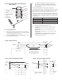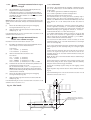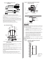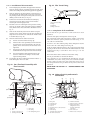
1
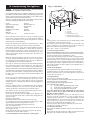
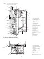
15.4.5 Control Board
15.4.6 Fan
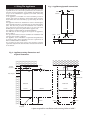
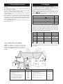
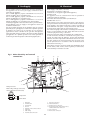
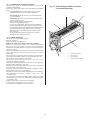
Lower the base plate/control assembly and carefully disconnect
the plug-in connector and all the electrical connections. Refer to
Fig. 35.
Release the five clips and lift out the control board. Refer to Fig. 35.
Pull out and replace, if necessary, a failed fuse.
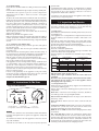
Remove the inner casing and combustion chamber cover .
Remove the fan as described in Section 14.3 Inspection and
Servicing. The flue hood gasket should be replaced if it is
damaged or has deteriorated.
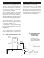
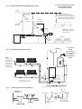
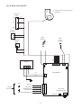
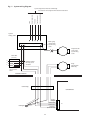
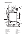
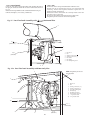
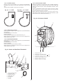
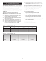
Ensure that all the connections are correctly made to the new
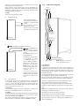
fan. Refer to Fig. 37 and 37a.
Do not use any sealant on the fan/flue duct connection.
The polarity of wires onto the fan is not important.
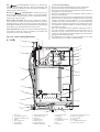
Fig. 37 . Fan/Flue hood Assembly with
Horizontal Flue
5
4( )
(clear tube)
6
+
7
1.
2.
3.
4.
5.
6.
7.
3 (+)
(red tube)
Flue hood
Fan
Sensing connection (+)
Sensing connection ( )
Flue turret
Fan clamp
Fan clamp fixing screw
1
2
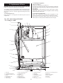
Fig. 37a . Fan/Flue hood Assembly with Rear Only Flue
NOTE: The polarity of wires is
not important
5
6
1.
2.
3.
4.
5.
6.
7.
8.
9.
10.
9
—ve
1
Flue hood
Fan
Sensing connection (+)
Sensing connection (—)
Top outlet sealing plate
Fan lead clip
Fan fixing screws (2)
Pressure tube junction
— ve pressure tube
+ ve pressure tube
10
+ve
8
7
4(—)
(clear tube)
+
3 (+)
(red tube)
2
29