1
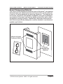
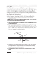
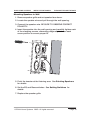
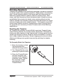
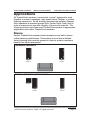
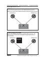
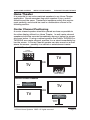
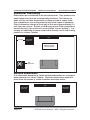
ELAN HOME SYSTEMS
INSTALLATION MANUAL
THP525W/THP650W/THP650D
Contents
Introduction ....................................................................... 2-4
Specifications ......................................................................... 2
Features .................................................................................. 4
Installation ....................................................................... 5-22
Prewiring ................................................................................. 5
Mounting ............................................................................... 10
Pointing Speakers ................................................................ 20
Setting Switches ................................................................... 22
Painting ................................................................................ 23
Applications ................................................................... 25-38
Stereo .................................................................................... 25
Home Theater ....................................................................... 27
Limited Warranty ............................................... Back Page
© ELAN Home Systems 2005 • All rights reserved.
Page 1
THP525W/THP650W/THP650D
INSTALLATION MANUAL
ELAN HOME SYSTEMS
Introduction
Congratulations and thank you for purchasing ELAN TheaterPoint
speakers. The TheaterPoint speaker line has been designed specifically to match the needs of dedicated Home Theater and critical
listening areas within the home. Using state-of-the-art materials like
woven Kevlar fiber cones, neodymium magnets, and aluminum phase
plugs each speaker seamlessly reproduces movie soundtracks and
music with the clarity and precision demanded in today’s multi-channel environments. Advanced features such as three-way EQ switches,
bass limiting circuits, custom Q crossovers, and pivoting tweeters allow flexibility and customization for virtually any circumstance where
accurate audio reproduction is paramount.
TheaterPoint speakers have been designed as a family. Each speaker
complements the others. All use similar components to create a
coherent audio experience no matter what the content. TheaterPoint
speakers are also designed to provide custom solutions for virtually
any multi-room environment. In-wall, in-ceiling, on-wall, and freestanding speakers combine to create the exact setup that each home
requires. No matter which combination is appropriate, TheaterPoint
speakers provide sonic accuracy and reproduce all audio sources to
ELAN’s exacting standards.
Specifications
THP525W
System Type ..................................................... Dual Woofer w/ Pivoting Tweeter
Woofer
Cone .................................... 2 X 5.25" Woven Kevlar w/Aluminum Phase Plug
Magnet .............................................................................. Shielded Neodymium
Surround ......................................................................................... Butyl Rubber
Basket .......................................................................................... Cast Aluminum
Tweeter
Diaphragm ........................................ 1" (25mm) Pivoting Woven Kevlar Dome
Magnet ............................................................................. Shielded Neodymium
Crossover ............................................................... 3rd Order Custom Q @ 2.4kHz
Switches ............................................. EQ (Bright/Neutral/Warm) & Bass Limiting
Nominal Impedance ................................................................................... 6 Ohms
Sensitivity ........................................................................................................ 88dB
Frequency Response ...................................................................... 55Hz to 20kHz
Power Handling ............................................................................... 90 Watts RMS
Mounting
Frame Dimensions .................................................................. 8 3/8" x 15 7/16"
(213mm x 392mm)
Cutout Dimensions .....................................................................7 1/4" x 14 3/8"
(184mm x 365mm)
Depth ................................................................................................ 4" (102mm)
Weight ..............................................................................................11 lbs. (5kg)
Page 2
© ELAN Home Systems 2005 • All rights reserved.
ELAN HOME SYSTEMS
INSTALLATION MANUAL
THP525W/THP650W/THP650D
Specifications (cont’d.)
THP650W
System Type ..................................................... Dual Woofer w/ Pivoting Tweeter
Woofer
Cone ..................................... 2 X 6.5" Woven Kevlar w/Aluminum Phase Plug
Magnet ....................................................................... Shielded Double Ceramic
Surround ......................................................................................... Butyl Rubber
Basket ......................................................................................... Cast Aluminum
Tweeter
Diaphragm ........................................ 1" (25mm) Pivoting Woven Kevlar Dome
Magnet ............................................................................. Shielded Neodymium
Crossover ............................................................... 3rd Order Custom Q @ 2.2kHz
Switches ..............................................EQ (Bright/Neutral/Warm) & Bass Limiting
Nominal Impedance .................................................................................. 6 Ohms
Sensitivity ....................................................................................................... 90dB
Frequency Response ..................................................................... 40Hz to 20kHz
Power Handling ............................................................................. 110 Watts RMS
Mounting
Frame Dimensions .................................................................... 9 7/8" x 16 3/8"
(251mm x 416mm)
Cutout Dimensions ................................................................... 8 5/8" x 15 3/16"
(219mm x 386mm)
Mounting Depth ................................................................................ 4" (102mm)
Weight ...................................................................................... 12.5 lbs. (5.67kg)
THP650D
(Patent Pending)
System Type ............................................................................... Three-Way Dipole
Woofer
Cone ...................................................................................... 6.5" Woven Kevlar
Magnet .................................................................................... Shielded Ceramic
Surround ......................................................................................... Butyl Rubber
Basket ......................................................................................... Cast Aluminum
Midrange
Cone ................................................................................2 x 2.5" Woven Kevlar
Magnet .............................................................................. Shielded Neodymium
Surround ......................................................................................... Butyl Rubber
Basket ......................................................................................... Cast Aluminum
Tweeter
Diaphragm ................................ 2 x 3/4" (19mm) Pivoting Woven Kevlar Dome
Magnet .............................................................................. Shielded Neodymium
Crossover
Slope ................................................. 2nd Order Custom Q @ 300Hz and 6kHz
Switches ......................................................... EQ (Bright/Neutral/Warm) & Phase
Nominal Impedance .................................................................................. 6 Ohms
Sensitivity ........................................................................................................ 87dB
Frequency Response ..................................................................... 50Hz to 22kHz
Power Handling ............................................................................... 75 Watts RMS
Mounting
Frame Dimensions ................................................................... 8 3/8" x 15 7/16"
(213mm x 392mm)
Cutout Dimensions ..................................................................... 7 1/4" x 14 3/8"
(184mm x 365mm)
Depth ................................................................................................ 4" (102mm)
Weight ........................................................................................ 8.5 lbs. (3.86kg)
© ELAN Home Systems 2005 • All rights reserved.
Page 3
THP525W/THP650W/THP650D
INSTALLATION MANUAL
ELAN HOME SYSTEMS
Features
• Long-Throw Woven Kevlar Cone Woofers
• Woven Kevlar Dome Tweeters
• Cast Aluminum Baskets
• Shielded Neodymium/Shielded Ceramic Magnets
• Kevlar Fiber Dome Pivoting Tweeters w/ Neo
Magnet & Fluid Cooling
• Custom Q High Order Crossovers
• Inverted Butyl Rubber Surrounds
• Woofer Aluminum Phase Plugs
• EQ Switch
• Bass Limiting Switch (THP650W/THP525W)
• Phase Switch (THP650D)
• Glass-Filled ABS Frame w/ Dog-Ear Mounting
• Single Screw Locking Mechanism
• ‘TheaterPoint’ Pointing Laser Included
• Perforated, Rust-Resistant Grille
• Easy-To-Paint White Finish
Page 4
© ELAN Home Systems 2005 • All rights reserved.
ELAN HOME SYSTEMS
INSTALLATION MANUAL
THP525W/THP650W/THP650D
Installation
The Installation process is divided into two distinct processes, wiring
and mounting. After carefully considering the intended application
(defining a Listening Area, Home Theater/Stereo, etc.) specific mounting locations can be decided upon. Once the specific locations are
determined, installation can commence.
Wiring
Before actually running any wire or cable, take the time to look around
each room or area of the house and plan the wire paths for maximum
efficiency. Look for routes through uncluttered parts of the stud
wall or ceiling that allow you to group all low-voltage wires wherever
possible. It is a good practice to label both ends of all cables and to
protect wires by tying a plastic bag over the ends.
Label
Plastic Bag
REAR
LEFT
SPK
Note 1: Low voltage wiring must be run in accordance with the National Electrical Code as well as any other applicable provisions of the
local building codes in your area. In some cases (such as commercial
installations), running the wire in conduit may be required. If you have
any questions concerning the wiring of speakers in your home, contact your local building and inspection department.
Note 2: It is recommended that you use quality CL2 or CL3 rated
stranded speaker wire when installing ELAN TheaterPoint speakers.
Solid-core “Romex” type wire is not acceptable! Use at least 16AWG
speaker wire for runs up to 100 feet, and at least 14 AWG speaker
wire for runs up to 200 feet. If you must cross high-voltage lines,
always do so at a 90 degree angle to avoid audible hum through the
speakers!
© ELAN Home Systems 2005 • All rights reserved.
Page 5
THP525W/THP650W/THP650D
INSTALLATION MANUAL
ELAN HOME SYSTEMS
Wiring (cont’d.)
The audio/speaker cable runs should be routed from the head-end
location to the speaker rough-in brackets (if used). At the speaker
locations, securely fasten the speaker wire to the rough-in bracket.
Min
12”
Speaker
Wire
High
Voltage
Wiring
WARNING: Do Not Run Speaker
Wires Through Holes Shared
By High-Voltage Wiring!
Page 6
© ELAN Home Systems 2005 • All rights reserved.
ELAN HOME SYSTEMS
INSTALLATION MANUAL
THP525W/THP650W/THP650D
Wiring (cont’d.)
If speaker rough-in brackets are not being utilized, speaker wire runs
should be stapled in a loose zigzag between the studs where the
speaker is to be mounted in order to make it easier to find the cable
after the drywall is installed. Zig-zagging the cable also allows flexibility in the placement of the speaker.
© ELAN Home Systems 2005 • All rights reserved.
Page 7
THP525W/THP650W/THP650D
INSTALLATION MANUAL
ELAN HOME SYSTEMS
In-Wall Stereo Speaker Pairs
There are three common scenarios for connecting stereo speaker
pairs to a distributed audio system:
• One 4-conductor speaker wire runs from the amplifier to one
speaker w/ 2 conductors connected. The second 2-conductors
are spliced and connected to a 2-conductor speaker wire that
runs to the second speaker.
• Two separate two-conductor speaker wires run from the amplifier
to each stereo speaker.
Amplifier
• One four-conductor speaker wire runs from the amplifier to a
stereo volume control, then one two-conductor speaker wire
runs to each stereo speaker.
Amplifier
Volume
Control
Page 8
© ELAN Home Systems 2005 • All rights reserved.
ELAN HOME SYSTEMS
INSTALLATION MANUAL
THP525W/THP650W/THP650D
In-Wall Surround Speakers
Typically, Home Theater surround speakers are connected directly
from the amplifier to the speakers without the use of a volume control.
A/V Receiver
WARNING: Turn Off Power to Amplifier
Before Connecting Speakers!
© ELAN Home Systems 2005 • All rights reserved.
Page 9
THP525W/THP650W/THP650D
INSTALLATION MANUAL
ELAN HOME SYSTEMS
Mounting
There are two situations that can exist when mounting in-wall
speakers:
Pre-Construction - Installations that occur in new homes being built
and in remodel situations where walls and/or ceilings will be exposed.
Retro-Fit - Installation that involve existing homes with walls and
ceilings finished.
While the end result of either type of installation is similar, the process
is quite different.
Pre-Construction
In a pre-construction installation, walls and ceilings are open with
no drywall installed. This is desirable and allows the installer much
greater access than in retro-fit applications. ELAN TheaterPoint
Rough-In Brackets are specifically designed to work with these
speakers and should be used whenever possible to reserve a neat
hole in the drywall, ensuring proper placement of speakers and making trim-out and final installation neat and organized. See the chart
on the next page for the correct rough-in bracket for the speaker being installed.
Referring to the floor plan marked with component locations, install
all speaker rough-in brackets. Be sure that the bracket frame is
facing out for drywall cutting accuracy. All rough-in brackets must
be securely mounted to wall studs and cannot be installed after the
drywall is up!
Page 10
© ELAN Home Systems 2005 • All rights reserved.
ELAN HOME SYSTEMS
INSTALLATION MANUAL
THP525W/THP650W/THP650D
Rough-In Brackets
The chart below details the correct rough-in bracket for each TheaterPoint speaker.
Bracket
Compatible Speakers
BKT56W
BKT8C
THP525W/THP650D
BKT800W
THP800C/THP801/THP802/THP803
THP650W
IMPORTANT NOTES:
• When the BKT800W Rough-In Bracket is mounted horizontally,
it will not fit in a standard wall stud bay. For horizontal mount
ing, the distance between wall studs must be at least 14 1/2”.
For new construction scenarios, provisions must be made for the
width of the speaker if the BKT800W/THP650W will be mounted
horizontally. For retrofit applications, ELAN recommends either
mounting the BKT800W/THP650W vertically or using the
BKT56W/THP525W (mounted horizontally) for the center channel.
Since all TheaterPoint Speakers have matching voices when used
in combination, use the THP525W as a center channel speaker
and THP650Ws as the left and right channels of a Home Theater.
• The THP800W uses the same rough-in bracket as the 8" M•Series
in-wall speakers; the BKT800W.
• THP800C/THP801/THP802/THP803 are compatible with the
BKT8C only. They are NOT compatible with the M•Series 8"
in-ceiling rough-in bracket; the BKT800C.
• The BKT56W requires at least 14 1/2" clearance. If the wall studs
are not exactly centered at 16", the bracket will not fit correctly.
© ELAN Home Systems 2005 • All rights reserved.
Page 11
THP525W/THP650W/THP650D
INSTALLATION MANUAL
ELAN HOME SYSTEMS
Mounting Rough-In Brackets
1. Decide on the installation location for the speakers.
WARNING: Be sure mounting
locations are clear of high-voltage
wiring, pipes, or other obstructions.
2. Attach the Bracket Flanges to the Bracket Frame as shown
Note: Make sure the dimpled side of the flange faces OUT and
interlocks with the frame from the rear.
3. Secure the bracket assembly to the wall studs with flat-head
screws or heavy-duty staples.
Page 12
© ELAN Home Systems 2005 • All rights reserved.
ELAN HOME SYSTEMS
INSTALLATION MANUAL
THP525W/THP650W/THP650D
Mounting Rough-In Brackets (cont’d)
4. Once the drywall has been installed, carefully and accurately
cut out the speaker holes using a routing tool or similar device.
A drywall professional may perform this step.
After the drywall is up and the the holes are cut, the speaker frame
and speaker grille may be removed for painting (see Painting for
more details). It is also possible to install only the speaker frame and
speaker grille. Remove the speaker baffle until the jobsite is secure
then replace it when the final installation is taking place.
Mounting Speakers in Rough-In Brackets
1. Remove speaker grille and set speaker face down.
2. Locate the speaker wire and pull through the wall opening.
3. Connect the speaker wire. Be sure to observe correct polarity!
4. Insert the speaker into the the wall opening and carefully tighten
each clamping screw, alternating diagonally between each screw
position to ensure proper fit.
5. Once the speaker is mounted in the wall, point the tweeter.
See Pointing Speakers for details.
7. Set the EQ and Bass switches (EQ and Phase switches for
THP650D). See Setting Switches for details.
8. Replace the speaker grille.
© ELAN Home Systems 2005 • All rights reserved.
Page 13
THP525W/THP650W/THP650D
INSTALLATION MANUAL
ELAN HOME SYSTEMS
Speaker Enclosures
In certain applications, it may be desirable to build enclosures for
TheaterPoint in-wall speakers. In these situations, use the guidelines
presented below.
2 x 4 Studs
When installing TheaterPoint in-wall speakers into a pre-construction environment using 2" x 4" wall studs, 2 x 4 blocks can be placed
above and below the mounting location in order to seal the area
around the speaker. Use the chart below to determine appropriate
spacing of blocks to provide correct air space.
Speaker
Distance
THP525W
20 in.
THP650D
20 in.
THP650W
30 in.
ELAN recommends installing screws at 2" intervals on the inside and
outside drywall along studs and above/below the speaker to avoid
vibration and create a more air-tight space.
2" x 4"
Screws
at 2"
Intervals
2" x 4"
Wall
Studs
Drywall
Page 14
Drywall
© ELAN Home Systems 2005 • All rights reserved.
ELAN HOME SYSTEMS
INSTALLATION MANUAL
THP525W/THP650W/THP650D
Speaker Enclosures (cont’d)
2 x 6 Studs
When installing TheaterPoint in-wall speakers into a pre-construction
environment using 2" x 6" (or greater) wall studs, airtight back boxes
may be constructed. The following chart gives the aproximate volume
of back boxes built for each TheaterPoint in-wall speaker. Measurements shown in the chart are outside dimensions. Back boxes are
typically constructed of 2" x 6" lumber and 3/4" MDF (Medium Density
Fiberboard) and should be made to fit between studs. Use glue or
silicone sealant at all joints.
Speaker
Volume
Inside Dimensions % Fill
THP525W
13.5 L (976 cu. in.)
3.5 in. x 14.5 in. x 20 in.
25%
THP650D
13.5 L (976 cu. in.)
3.5 in. x 14.5 in. x 20 in.
25%
THP650W
24 L (2030 cu. in.)
3.5 in. x 14.5 in. x 30 in.
50%
2x6
2x6
Wall
Stud
3/4"
MDF
3/4"
MDF
2x6
© ELAN Home Systems 2005 • All rights reserved.
Page 15
THP525W/THP650W/THP650D
INSTALLATION MANUAL
ELAN HOME SYSTEMS
Speaker Enclosures (cont’d)
The completed enclosure should look similar to the drawing below.
When designing an enclosure to dimensions other than what is listed
in the chart on the previous page, ELAN recommends using a height
to width ratio of 1:1.5 in order to reduce resonance. The dimensions
shown in the chart take this into consideration.
Fill Material
It is important to use some type of material to fill the enclosure to
the percentage indicated in the chart on the previous page. This will
reduce vibration and give the enclosure the characteristics necessary
for optimum audio performance. ELAN recommends using fiberglass
insulation or polyester fiberfill for this purpose.
Note: Make sure that any fill material does not touch the speaker
magnet or the back of the cone. Place fill material on outside edges
of enclosure.
Page 16
© ELAN Home Systems 2005 • All rights reserved.
ELAN HOME SYSTEMS
INSTALLATION MANUAL
THP525W/THP650W/THP650D
Sound Dampening Material
The use of sound dampening material such as Dynamat® can dampen
bleed-through into adjoining rooms and improve the sound quality of
in-wall or in-ceiling speakers by reducing vibrations. The diagram below shows a typical in-wall speaker installation using sound dampening material on the back wall and the baffle surface (the wall in which
the speaker actually mounts). Additionally, there are products available that are specifically designed to reduce vibration in architectural
speaker applications.
Mount to Inside
Surface of Wall.
Sound
Dampening
Material
© ELAN Home Systems 2005 • All rights reserved.
Page 17
THP525W/THP650W/THP650D
INSTALLATION MANUAL
ELAN HOME SYSTEMS
Retro-Fit
Retro-fit installations are more difficult to complete than preconstruction because walls and ceilings are intact. Typically wires
must be fished into position through walls, floors and ceilings. Holes
must be cut and speakers mounted directly in the ceiling with no
rough-in brackets. Before cutting holes in any existing wall or
ceiling surface, probe the cavity behind each speaker’s installation location for obstructions!
Cutting Speaker Openings in Walls - No Rough-in Brackets
1. Use a stud finder to locate the studs around the intended
speaker location.
Note: A stud-finding device may not detect pipes, wiring, or other
obstructions located behind the drywall.
2. Use the inside portion of the speaker cutout template to confirm
speaker placement.
3. Remove templates and drill or carefully punch a pilot hole in the
wall. A bent piece of wire or a coat hanger may be use to probe
the stud bay for obstructions. If you experience resistance of any
kind–– STOP! If any obstructions are detected, patch the pilot
hole and try again in another location.
Ceiling
Pilot Hole
Wire or
Coat Hanger
4. Once it has been determined that the cavity is free from obstruc
tions, position the cutout template and use a pencil to lightly
trace the perimeter of the template.
5. Cut the opening using a keyhole saw, drywall router, or razor
knife.
Page 18
© ELAN Home Systems 2005 • All rights reserved.
ELAN HOME SYSTEMS
INSTALLATION MANUAL
THP525W/THP650W/THP650D
Mounting Speakers in Wall
1. Remove speaker grille and set speaker face down.
2. Locate the speaker wire and pull through the wall opening.
3. Connect the speaker wire. BE SURE TO OBSERVE CORRECT
POLARITY!
4. Insert the speaker into the wall opening and carefully tighten each
of the clamping screws, alternating diagonally between each
screw position to ensure proper fit.
5. Point the tweeter at the listening area. See Pointing Speakers
for details.
6. Set the EQ and Bass switches. See Setting Switches for
details.
7. Replace the speaker grille.
© ELAN Home Systems 2005 • All rights reserved.
Page 19
THP525W/THP650W/THP650D
INSTALLATION MANUAL
ELAN HOME SYSTEMS
Pointing Speakers
TheaterPoint speakers are specifically designed to produce outstanding audio quality when properly placed in relationship to the listening
area. Human hearing relies on mid-range and high frequencies to
determine spatial direction (where a sound is coming from). Midrange and high frequency drivers (tweeters) tend to produce narrow
soundfields that sound much better when pointing directly at the
listener whereas low frequency drivers (woofers) envelop much larger
areas and tend to be more omnidirectional. The tweeter can be finetuned using ELAN’s exclusive TheaterPointer Laser Pointing Device
for pinpoint sonic accuracy in Home Theaters and critical listening
applications.
Pointing the Tweeter
All TheaterPoint speakers include ELAN’s exclusive TheaterPointer
Laser Pointing Device for precise tweeter adjustment. Because the
human ear relies heavily on high frequencies to locate sound, and because high frequency drivers create a narrow soundfield, it is important to align tweeters precisely. Stereo imaging and surround sound
effects and dialogue are greatly improved by pointing the tweeter
correctly.
To Correctly Point the Tweeter:
1. Move the tweeter so that
it points toward the
desired listening position.
2. Turn TheaterPointer on by
pressing the power button.
3. Place the TheaterPointer
into the triangular hole
located on the tweeter’s
protective cover. Notice
the red beam of light
emanating from the
TheaterPointer.
Page 20
© ELAN Home Systems 2005 • All rights reserved.
ELAN HOME SYSTEMS
INSTALLATION MANUAL
THP525W/THP650W/THP650D
Pointing the Tweeter (cont’d.)
4. Position the tweeter such that the red spot of light is pointing
directly at the center of the listening area (as shown below).
5. Repeat this process for each TheaterPoint speaker in the system
with the exception of THP650D and THP650SS.
If Utilizing THP650D In-Wall Dipole or THP650SS Dipole speakers as
side rear channels of a 5.1, 6.1, or 7.1 surround sound system, the
tweeters should NOT point directly at the listening position. Instead,
they should point obliquely to the listening area as shown below.
TV
THP525W
THP650W
THP650W
X
THP650D
THP525W
© ELAN Home Systems 2005 • All rights reserved.
THP650D
THP525W
Page 21
THP525W/THP650W/THP650D
INSTALLATION MANUAL
ELAN HOME SYSTEMS
Setting Switches
Once the speakers are wired, mounted, and positioned correctly, use
the built-in switches to fine-tune the speakers based on local environmental variables or system design parameters. The switches are
labelled “EQ” (Equalizer) and “BASS” (for THP650W and THP525W).
The EQ switch compensates for the “liveness” or “deadness” of the
room while the BASS switch cuts bass by aproximately - 20dB. The
THP650D has an “EQ” switch and a “PHASE” switch. The “PHASE”
switch is essential for proper dipole functionality.
EQ Switch (THP650W/THP525W)
Select the W (Warm) position on the EQ switch to compensate for
“live” rooms where sound bounces and reflects from hard surfaces
like tile or hardwood floors, large glass surfaces/windows, stone
or brick walls, etc. Select the B (Bright) position to compensate for
“dead” rooms where sound is absorbed by soft materials like heavy
drapes, thick carpeting, upholstered furniture, etc. Use the N (Neutral)
position if no compensation is required.
Bright
Warm
Neutral
BASS Switch (THP650W/THP525W)
Select the + position for normal bass operation if the speaker is used
full-range without a subwoofer. Select the 0 position to reduce bass
frequencies by aprox. 20dB. The 0 option is designed to protect the
the speaker during high volume operation and should only be used
when a subwoofer is present in the system.
Reduced
Bass
Operation
Page 22
Normal
Bass
Operation
© ELAN Home Systems 2005 • All rights reserved.
ELAN HOME SYSTEMS
INSTALLATION MANUAL
THP525W/THP650W/THP650D
EQ Switch (THP650W/THP525W)
Select the -3 position on the EQ switch to compensate for “live”
rooms where sound bounces and reflects from hard surfaces like
tile or hardwood floors, large glass surfaces/windows, stone or brick
walls, etc. Select the +3 position to compensate for “dead” rooms
where sound is absorbed by soft materials like heavy drapes, thick
carpeting, upholstered furniture, etc. Use the 0 position if no
compensation is required.
Bright
Warm
0
3
-3
Neutral
PHASE Switch (THP650D)
It is extremely important that proper polarity (or “Phase”) is maintained when installing dipole speakers such as the THP650D. Each
speaker in a pair needs to have opposite polarity from the other in
order for the benefits of the dipole design to be realized. To ensure
proper polarity, the THP650D has a PHASE switch.
Set the PHASE switch after the speakers have been installed. Set the
left surround speaker (when facing the front of the room) to the “0”
position. Set the right surround speaker to the “180” position.
180
“180” Position:
Right Speaker
0
“0” Position:
Left Speaker
© ELAN Home Systems 2005 • All rights reserved.
Page 23
THP525W/THP650W/THP650D
INSTALLATION MANUAL
ELAN HOME SYSTEMS
Painting
All ELAN TheaterPoint speakers can be finished to match any room
décor. Their white, textured frames and no-rust aluminum grilles
readily accept most water-based interior latex and spray enamels.
We recommend the grille and frame be painted separately. To aid in
frame painting, a plastic paint shield is included that will protect the
speaker baffle.
Painting Tips:
• If not using spray paint, it is recommend that the paint be thinned
to prevent clogging of the speaker grille perforations.
• When painting, several light coats will yield the best results.
Page 24
© ELAN Home Systems 2005 • All rights reserved.
ELAN HOME SYSTEMS
INSTALLATION MANUAL
THP525W/THP650W/THP650D
Applications
All TheaterPoint speakers have similar “voices” designed to work
together to create a seamless, high-quality Home Theater or critical
listening experience. ELAN strongly recommends installing TheaterPoint speakers in matched groups (Left, Center, Right, Rear, Sub) in
order to preserve the acoustic integrity of the source material. The
following section describes each TheaterPoint speaker in appropriate
applications with other TheaterPoint speakers.
Stereo
Certain TheaterPoint speakers lend themselves very well to stereo
critical listening applications. Please keep in mind that a defined
stereo listening area must be present in order to acheive maximum
benefit from stereo placement.
THP525LS/THP650LS
THP650LS
or
THP525LS
THP650LS
or
THP525LS
THP525LS/THP650LS/THP1200SW
THP1200SW
Subwoofer
THP650LS
or
THP525LS
© ELAN Home Systems 2005 • All rights reserved.
THP650LS
or
THP525LS
Page 25
THP525W/THP650W/THP650D
INSTALLATION MANUAL
ELAN HOME SYSTEMS
Stereo Applications (cont’d.)
THP800 Series
Critcal listening areas require a well-defined listening position.
Make sure to point the speakers toward the listening area as shown.
THP800 Series
THP800 Series
X
THP800 Series/THP1200SW
Add a THP1200SW subwoofer to increase bass response. This
adds richness to the music and makes a huge improvement in
sound quality.
THP800 Series
THP800 Series
THP1200SW
Subwoofer
X
Page 26
© ELAN Home Systems 2005 • All rights reserved.
ELAN HOME SYSTEMS
INSTALLATION MANUAL
THP525W/THP650W/THP650D
Home Theater
It is essential to use voice-matched speakers in any Home Theater
application. Sound emanates from each speaker in turn, and all
should sound the same. TheaterPoint speakers satisfy this requirement perfectly, and should be used in combinations shown in the
following section.
Center Channel Positioning
A center channel speaker should be placed as close as possible to
the video display utilized in a Home Theater. In-wall center channel
speakers should be mounted immediately above or below the screen
as shown below. If using a cabinet speaker like ELAN’s THP525LS or
THP650LS as a center channel, position it on a stand immediately below the screen. A Center Channel speaker can also mount on a shelf
above the screen - possibly in a cabinet or entertainment center.
In-Wall Center Channel
In-Wall
Center Channel
TV
OR
TV
In-Wall
Center Channel
Cabinet Center Channel
Shelf
Cabinet
Center Channel
TV
OR
TV
Cabinet
Center Channel
Speaker
Stand
© ELAN Home Systems 2005 • All rights reserved.
Page 27
THP525W/THP650W/THP650D
INSTALLATION MANUAL
ELAN HOME SYSTEMS
Subwoofer Positioning
Subwoofers are considered to be omnidirectional. They produce low
bass frequencies that are not especially localized. The human ear
does not rely on these frequencies to place sounds in space therefore, placement is not as important as with other types of speakers.
Place subwoofers along the front wall of the room approximately 2-3
feet from the corners. Expect a 3-9dB bass boost if the subwoofer is
placed directly in the corner of a room (called “corner loading”). It is
usually not advisable to place subwoofers directly next to the seating
position in a Home Theater.
TV
2-3 Feet
THP1200SW
Subwoofer
Subwoofers May Be
Placed on Either
Side of Screen
X
THP1200SW
Subwoofer
Not
Recommended
Multiple Subwoofers
It is sometimes desirable to install multiple subwoofers for increased
bass response in a Home Theater. Place the subwoofers equal distance from the screen in similar locations as shown below.
TV
THP1200SW
Subwoofer
Page 28
THP1200SW
Subwoofer
© ELAN Home Systems 2005 • All rights reserved.
ELAN HOME SYSTEMS
INSTALLATION MANUAL
THP525W/THP650W/THP650D
5.1 Surround Sound Applications
THP525LS/THP650LS - Free-Standing L/C/R
THP650SS - On-Wall Dipole Rear Side
THP1200SW - Subwoofer
TV
THP1200SW
Subwoofer
THP650LS
or
THP525LS
THP650LS
or
THP525LS
THP650LS
or
THP525LS
THP650SS
THP650SS
THP800 Series - In-Ceiling L/C/R & Rear
THP1200SW - Subwoofer
THP1200SW
Subwoofer
TV
THP800 Series
THP800 Series
THP800 Series
© ELAN Home Systems 2005 • All rights reserved.
THP800 Series
THP800 Series
Page 29
THP525W/THP650W/THP650D
INSTALLATION MANUAL
ELAN HOME SYSTEMS
5.1 Applications (cont’d.)
THP525W - In-Wall L/C/R
THP650D - In-Wall Dipole Rear Side
THP1200SW - Subwoofer
TV
THP1200SW
Subwoofer
THP525W
THP525W
THP650D
THP525W
THP650D
THP650W - In-Wall L/C/R & Rear
THP1200SW - Subwoofer
TV
THP1200SW
Subwoofer
THP650W
THP650W
THP650W
THP650W
Page 30
THP650W
© ELAN Home Systems 2005 • All rights reserved.
ELAN HOME SYSTEMS
INSTALLATION MANUAL
THP525W/THP650W/THP650D
5.1 Applications (cont’d.)
THP650W - In-Wall Left/Right
THP525W - In-Wall Center
THP650D - In-Wall Dipole Rear Side
THP1200SW - Subwoofer
TV
THP1200SW
Subwoofer
THP525W
THP650W
THP650W
THP650D
THP650D
THP525LS/THP650LS - Free-Standing L/C/R
THP650D - In-Wall Dipole Rear Side
THP1200SW - Subwoofer
TV
THP1200SW
Subwoofer
THP650LS
or
THP525LS
THP650LS
or
THP525LS
THP650D
© ELAN Home Systems 2005 • All rights reserved.
THP650LS
or
THP525LS
THP650D
Page 31
THP525W/THP650W/THP650D
INSTALLATION MANUAL
ELAN HOME SYSTEMS
5.1 Applications (cont’d.)
THP525LS/THP650LS - Free-Standing L/C/R
THP800 Series - In-Ceiling Rear
THP1200SW - Subwoofer
TV
THP1200SW
Subwoofer
THP650LS
or
THP525LS
THP650LS
or
THP525LS
THP800 Series
THP650LS
or
THP525LS
THP800 Series
THP650W - In-Wall L/C/R
THP800 Series - In-Ceiling Rear
THP1200SW - Subwoofer
TV
THP1200SW
Subwoofer
THP650W
THP650W
THP650W
THP800 Series
Page 32
THP800 Series
© ELAN Home Systems 2005 • All rights reserved.
ELAN HOME SYSTEMS
INSTALLATION MANUAL
THP525W/THP650W/THP650D
5.1 Applications (cont’d.)
THP525W - In-Wall L/C/R
THP800 Series - In-Ceiling Rear
THP1200SW - Subwoofer
TV
THP1200SW
Subwoofer
THP525W
THP525W
THP525W
THP800 Series
THP800 Series
THP525W - In-Wall Center
THP650W - In-Wall L/R
THP800 Series - In-Ceiling Rear
THP1200SW - Subwoofer
TV
THP1200SW
Subwoofer
THP525W
THP650W
THP650W
THP800 Series
THP800 Series
© ELAN Home Systems 2005 • All rights reserved.
Page 33
THP525W/THP650W/THP650D
INSTALLATION MANUAL
ELAN HOME SYSTEMS
6.1/7.1 Surround Sound
6.1 and 7.1 surround sound systems utilize additional rear and/or rear
side speakers to enhance the audio effects contained in a soundtrack.
Any of the previous examples can easily become a 6.1 or 7.1 system
by changing the configuration of the rear channels. The diagrams in
this section show rear and side rear speakers only!
6.1 Systems
Typical 6.1 systems use two rear side speakers with a center rear
speaker. Several logical combinations can be created using TheaterPoint speakers as shown in the following examples.
THP800 Series - In-Ceiling Rear
THP800 Series
THP800 Series
THP800 Series
THP650D - In-Wall Rear Side
THP525W - In-Wall Rear Center
THP650D
THP525W
THP650D
THP650SS - On-Wall Rear Side
THP525W - On-Wall Rear Center
THP650SS
THP650SS
THP650LS
Page 34
© ELAN Home Systems 2005 • All rights reserved.
ELAN HOME SYSTEMS
INSTALLATION MANUAL
THP525W/THP650W/THP650D
6.1 Applications (cont’d.)
THP650W - In-Wall Rear
THP650W
THP650W
THP650W
THP525W - In-Wall Rear
THP525W
THP525W
THP525W
THP525W - In-Wall Rear Center
THP650D - In-Wall Rear Side
THP650D
THP650D
THP525W
© ELAN Home Systems 2005 • All rights reserved.
Page 35
THP525W/THP650W/THP650D
INSTALLATION MANUAL
ELAN HOME SYSTEMS
7.1 Systems
Use a total of four speakers for rear Surround effects when configuring 7.1 systems. Several logical combinations can be created using
TheaterPoint speakers as shown in the following examples.
THP800 Series - In-Ceiling Rear and Rear Side
THP800 Series
THP800 Series
THP800 Series
THP800 Series
THP650D - In-Wall Rear Side Speakers
THP650W - In-Wall Rear Speakers
THP650D
THP650D
THP525W
THP525W
THP650SS - On-Wall Rear Side
THP650LS - On-Wall Rear
THP650SS
THP650SS
THP650LS
Page 36
THP650LS
© ELAN Home Systems 2005 • All rights reserved.
ELAN HOME SYSTEMS
INSTALLATION MANUAL
THP525W/THP650W/THP650D
7.1 Applications (cont’d.)
THP650W - In-Wall Rear and Side
THP650W
THP650W
THP650W
THP650W
THP525W - In-Wall Rear and Rear Side
THP525W
THP525W
THP525W
THP525W
THP650D - In-Wall Rear Side
THP525W - In-Wall Rear
THP650D
THP650D
THP525W
THP525W
© ELAN Home Systems 2005 • All rights reserved.
Page 37
THP525W/THP650W/THP650D
INSTALLATION MANUAL
ELAN HOME SYSTEMS
High Performance 7.1 Surround System
THP650LS - Free-Standing L/C/R
THP650SS - On-Wall Rear Side
THP525LS - On-Wall Rear
THP1200SW - Subwoofers
TV
THP1200SW
Subwoofer
THP1200SW
Subwoofer
THP650LS
THP650LS
THP650LS
THP650SS
THP650SS
THP525LS
Page 38
THP525LS
© ELAN Home Systems 2005 • All rights reserved.
ELAN HOME SYSTEMS
INSTALLATION MANUAL
THP525W/THP650W/THP650D
Notes:
© ELAN Home Systems 2005 • All rights reserved.
Page 39
THP525W/THP650W/THP650D
INSTALLATION MANUAL
ELAN HOME SYSTEMS
Notes:
Page 40
© ELAN Home Systems 2005 • All rights reserved.
Limited Lifetime Warranty
ELAN HOME SYSTEMS L.L.C. (“ELAN”) warrants to the original
purchaser only that THP525W, THP650W, and THP650D speakers
are free from defects in materials and workmanship provided that
the product was purchased from an authorized ELAN Home Systems Dealer. If the purchaser discovers that such item was not as
warranted above and promptly notifies ELAN in writing, ELAN shall
repair or replace the item at the company’s option. This warranty
shall not apply (a) to equipment not manufactured by ELAN, (b) to
equipment which shall have been installed by other than an ELAN
authorized installer, (c) to installed equipment which is not installed
to ELAN’s specifications, (d) to equipment which shall have been
repaired or altered by others than ELAN, (e) to equipment which
shall have been subjected to negligence, accident, or damage by
circumstances beyond ELAN’s control, including, but not limited
to, lightning, flood, electrical surge, tornado, earthquake, or other
catastrophic events beyond ELAN’s control, or to improper operation, maintenance or storage, or to other than normal use of service.
With respect to equipment sold by, but not manufactured by ELAN,
the warranty obligations of ELAN shall in all respects conform to the
warranty actually extended to ELAN by its supplier. The foregoing
warranties do not cover reimbursement for labor, transportation,
removal, installation or other expenses which may be incurred in
connection with repair or replacement.
Except as may be expressly provided and authorized in writing by
ELAN, ELAN shall not be subject to any other obligations or liabilities whatsoever with respect to equipment manufactured by ELAN
or services rendered by ELAN.
THE FOREGOING WARRANTIES ARE EXCLUSIVE AND IN LIEU OF
ALL OTHER EXPRESSED AND IMPLIED WARRANTIES EXCEPT
WARRANTIES OF TITLE, INCLUDING BUT NOT LIMITED TO IMPLIED WARRANTIES OF MERCHANTABILITY AND FITNESS FOR A
PARTICULAR PURPOSE.
ATTENTION: TO OUR VALUED CONSUMERS
To ensure that consumers obtain quality pre-sale and after-sale
support and service, ELAN Home Systems products are sold exclusively through authorized dealers. ELAN products are not sold
online. The warranties on ELAN products are NOT VALID if the
products have been purchased from an unauthorized dealer or an
online E-tailer. To determine if your ELAN reseller is authorized,
please call ELAN Home Systems at (859) 269-7760.
P/N9900715 REV:D