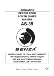
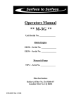
1
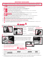
B ui
lding
Quality
4 Yea
Ice Fishing Equipment For Over 6
rs
OPERATING MANUAL
Strike-Lite II / 4-Stroke
4-Stroke Powe
aster’s
r Au
ger
ikeM
Str
Strike-Lite
II
t
!
ATTENTION
t
• Quiet Operation
• 4-Cycle
• Unleaded Fuel
!
You MUST add Crankcase Oil to
your new Auger prior to your
first use! We recommend
using StrikeMaster's
10W30 Weight
Conventional cold
weather 4-Cycle Oil
included with this auger.
ATTENTION:
FOR BEST PERFORMANCE IDLE ENGINE FOR 1-2 MINUTES
BEFORE YOU START DRILLING.
StrikeMaster Corporation
17217 198th Avenue • Big Lake, Minnesota 55309
Phone (763) 263-8999 • Fax (763) 263-8986
www.strikemaster.com
It is recommended that everyone who uses this product should read the StrikeMaster OPERATING
MANUAL and view the videos at http://www.strikemaster.com/video.html before operating
SM11
Ice Fishing has become one of the fastest growing and most popular winter sports,
allowing the ardent angler the opportunity to enjoy his or her favorite outdoor activity.
When you selected a StrikeMaster power ice auger, you selected a product that has
gained a reputation as the quality leader since 1946. And, there is no doubt that this
year's model is the finest ever produced by StrikeMaster Corporation.
Your new StrikeMaster ice auger has all of the most wanted features in a power ice
auger, to assure many years of enjoyable ice fishing. Some of these features such as
workmanship, engineering excellence, and dependability have long been standards at
StrikeMaster. Your new power ice auger boasts many new features while retaining the
best features developed in previous years to enhance your ice fishing experience and
add to your satisfaction in selecting StrikeMaster.
We know that you are anxious to go fishing and use your new power ice auger, but
before you go fishing, it is important and to your advantage to spend a few minutes
getting acquainted with your new StrikeMaster power ice auger. There is no better
way to acquaint yourself with the product than to read the Owners Manual and
Operating Instructions. A few minutes spent studying this manual before your first ice
fishing outing will be time well spent.
Record your Model and Serial No.'s immediately after purchase (see bottom of pg.
10). Also, please return the enclosed WARRANTY CARD or submit information on our
website to validate your limited warranty.
t
t
!
TABLE OF CONTENTS
Important Safeguards
Adjustments
Assembly Instructions
Maintenance
Fuel Requirements
2
7
2
5-7
4-5
Service Information
Starting/Operation
Stopping Engine
Storage
Warranty Card
t
!
ATTENTION
3
2, 5
3, 5-6
7
10
t
!
THIS SYMBOL POINTS OUT IMPORTANT SAFETY INSTRUCTIONS
WHICH IF NOT FOLLOWED COULD ENDANGER THE PERSONAL
SAFETY AND/OR PROPERTY OF YOURSELF AND OTHERS. READ AND
FOLLOW ALL INSTRUCTIONS IN THIS MANUAL AND ANY PROVIDED
WITH OR ON THE EQUIPMENT ON WHICH THIS ENGINE IS USED
BEFORE ATTEMPTING TO OPERATE YOUR STRIKEMASTER POWER
ICE AUGER.
!
Your new 4-stroke auger engine does NOT come with oil or
gasoline. You will need to add oil and gasoline prior to your
first use. Use unleaded gas only. Using a gas/oil mixture will
damage the motor.
Fill crankcase with StrikeMaster's Conventional 4-Cycle Oil, included
with this manual (See instructions).
See page 4 for complete instructions for adding fuel and oil to your new
auger.
IMPORTANT SAFEGUARDS
It is recommended that everyone who uses this product should read the StrikeMaster OPERATING
MANUAL and view the videos at http://www.strikemaster.com/video.html before operating
8.
9.
10.
11.
12.
13.
14.
15.
16.
!
!
!
!
!
!
!
!
!
!
!
!
!
DO NOT use this product for any purpose other than cutting ice fishing holes. Ice augers are precision cutting tools
built for the ice fisherman, and must be properly maintained and handled with caution during both cutting and
transporting. When not in use, always store with blade guard attached.
DO NOT use attachments other than those available from the manufacturer.
DO NOT alter this product in any manner; doing so is dangerous and voids all warranties.
DO NOT allow children or adults weighing under 100 lbs. to operate this equipment.
DO NOT operate under the influence of drugs or alcohol.
DO NOT allow your body, loose clothing, drawstrings, scarves, hats or other materials to come in contact with the
Powerhead, Starter Assembly or Auger (Drill) unit at any time.
DO NOT operate if, upon pulling the starter rope or after drilling holes, the auger (drill) unit rotates or if the rope pulls
hard. DO NOT OPERATE. Have the unit checked by a qualified mechanic.
DO NOT allow the engine to run or operate while moving or transporting to another location.
DO NOT continue to use this product in the event of mechanical or electrical failure.
This product produces considerable cutting force that is felt by the operator. Make sure your feet are firmly planted and
that the handles are held firmly while operating this product.
Always check the operation of the throttle system to ensure the carburetor control is completely returning
to the idle position when the throttle lever is released.
Check cutting blades and auger shaft screws before and after each use to make sure they are tight.
During operation, the auger unit could possibly stop. Be prepared at all times to release the throttle lever.
Everyone who uses this product should read this manual before operating this unit.
The cutting blades on the ice auger are razor sharp. Use extreme care when handling.
The manufacturer recommends that all augers, Lazer Mag Xpress, Strike-Lite, Lazer 224, Mag 2000, Magnum, Lazer Mag, Lazer Pro
and Electra Lazer 12000 DP be used for ice cutting only.
t
7.
!
!
Assembly
t
2.
3.
4.
5.
6.
t
t
t
t
t
t
t
t
t
t
t
t
t
t
1.
!
Carefully remove blade guard and make sure blade bolts are tight.
Remove Metric Allen wrench and unscrew the collar bolt from auger.
LAZER BLADE
2
1
Metal Collar
Allen Wrench
Collar Bolt
8mm bolts and 8mm closed
end wrench
3
Plastic Collar
The large and small
holes from each
component must line
up before installing
the collar bolt
Push down and twist
to line up holes
Large Holes
Remove Black plastic cap from drive shaft. Insert auger into drive shaft and install collar bolt.
Black Cap
Collar bolt inserts into the large hole, passes through the
drive shaft and threads into the small hole of the metal
collar. Make sure bolt is tight. Some wiggle is normal
between the power head and auger. Check and tighten
often.
Drive Shaft
5. It is recommended that the collar bolt be checked and torqued
firmly before and after every use.
t
!
Operation
Allen Wrench Storage
t
4. After assembly is complete, you can conveniently store your allen
wrench on the underside of the throttle pedal.
!
1. Start engine as explained in this manual.(See page 4-7). For best cutting performance, run
engine at idle for one minute before drilling.
2. Hold the unit in a vertical position with your right hand pushing downward to open throttle, and your left hand firmly
holding the opposite handle.
3. This product produces considerable cutting force that is felt by the operator. Make sure your feet are firmly planted and
that the handles are held firmly while operating this product, centrifugal clutch will engage and the auger will begin to
rotate.
4. During the operation of cutting, the auger could possibly stop if it comes in contact with a foreign object or if it binds in the
hole. Be prepared at all times to release the throttle lever to avoid rotation of the handle assembly.
2
5. After cutting ice fishing holes, the unit should be placed on the ice in a horizontal position,
making sure that the gas tank is facing down*. Be sure to replace the blade guard to protect
against personal injury, damage to the auger shaft or blade(s). (Never store or stand an ice
auger upright in a partially drilled ice fishing hole.)
Note: In ice depths deeper than the flighting of the auger, it is helpful to bring the auger up some
to remove the ice chips, this will make the remaining ice easier to drill.
Stop Engine
t
t
!
!
1. After completing the cutting of an ice fishing hole, STOP the engine by allowing the engine to return to idle and moving the
ignition switch to the OFF position. If the engine fails to stop, move the choke lever to the FULL CHOKE position to kill the
engine. Always check the throttle system to ensure the carburetor throttle lever is returning to the idle position. If the ignition
switch should fail, DO NOT operate until the ignition switch has been repaired by a qualified mechanic.
2. Attach the blade guard to protect blade(s).
3. The cutting blades on the ice augers are razor sharp. Use extreme care when handling.
4. Use caution when removing or replacing blade guard.
5. Use caution when replacing auger blades.
6. Always keep the blade guard on auger, except when in use.
7. The use of this auger by children is not recommended.
Customer Service
Continued satisfying performance from your StrikeMaster power ice auger may be assured by applying a minimum amount of
preventive maintenance. When it is required the following information is intended to inform you as to where and how you may obtain
additional service support.
Contact StrikeMaster Corporation at 763-263-8999 for the service center nearest you. Or, visit our website for assistance in
servicing your Strike-Lite II auger: www.strikemaster.com/servicecenters.html
If for any reason you are in doubt, or have any questions regarding the proper operation, and use of this product, or warranty
information please feel free to call during regular business hours or write to: (Sorry - No Collect Calls)
StrikeMaster Corporation
17217 198th Avenue • Big Lake, Minnesota, USA 55309
Phone: (763) 263-8999 Fax: (763) 263-8986
www.strikemaster.com
For engine adjustments, repairs or warranty service contact ROBIN AMERICA SERVICE at 1-630-350-8200 or visit their
website www.robinamerica.com. If you cannot locate a dealer please call one of the following distributors closest to you for
assistance: or StrikeMaster at 763-263-8999
The Bentley Company
4109 Airport Way So.
Seattle, WA 98108
800-628-5827
Capital Engine Co.
97 Cypress St. SW
Reynoldsburg, OH 43068
740-964-0089
Central Motive Power
6301 North Broadway
Denver, CO 80216
800-822-4332
Central Motive Power
3740 Princeton Dr. NE
Albuquerque, NM 87103
800-782-2525
Cullum & Brown of Wichita
1607 Wabash
Wichita, KS 67214
800-362-3222
Engine Center
2351 Hilton Rd.
Ferndale, MI 48220
800-726-8870
FSR
10705 Stoner Dr.
Fredricksburg, VA 22408
888-540-9067
Highway Equipment & Supply
1016 W. Church St.
Orlando, FL 32805
800-827-6495
Northern Engine and Supply Inc.
2929 W. Superior St.
Duluth, MN 55806
218-628-2836
O'Neill Associates
795 Canning Parkway
Victor, NY 14564
800-724-3145
Oscar Wilson Engines & Parts, Inc.
826 Lone Star Drive
O'Fallon, MO 63366
800-873-6722
Small Engine Clinic
98-019 Kamehameha Hwy.
Aiea, HI 96701
808-488-0711
Southeast Service & Supply
1721 "E" Oakbrook Drive
Norcross, GA 30093
800-241-4595
Southwest Products Corp.
5143 W. Roosevelt
Phoenix, AZ 85043
602-269-3581
Southwest Products Corp.
2760 Junipero Ave.
Long Beach, CA 90806
562-424-0913
Sullivan Bros., Inc.
P.O. Box 461, 139 Robbins Rd.
Downingtown, PA 19520
800-222-3636
Highway Equipment & Supply
4850 Collins Rd. #103
Orange Park, FL 32073
800-827-3019
Highway Equipment & Supply
6015 U.S. Highway 301 N.
Tampa, FL 33610
800-827-9092
Kimbers Inc.
115 N Geddes St.
Syracuse, NY 13204
800-627-1660
Kimbers Inc.
215 Broad St.
Oneida, NY 13421
315-363-4700
King McIver Sales Inc.
6375 Burnt Poplar Rd.
Greensboro, NC 27409
800-632-1373
M & L Engine
1212 St. Charles Street
Houma, LA 70360
800-960-0068
Marr Brothers, Inc.
423 East Jefferson Blvd.
Dallas, TX 75203
800-627-7276
Northern Engine and Supply Inc.
2710 3rd Avenue North
Fargo, ND 58102
800-272-3284
3
Tri State Engine Service
6125 Valley Dr.
Bettendorf, IA 52722
800-289-8676
Wilder Motor & Equipment Co.
301 15th Ave. North
Nashville, TN 37203
615-329-2365
Wilder Motor & Equipment Co.
1219 Rosewood Dr.
Columbia, SC 29201
800-922-9564
Wilder Motor & Equipment Co.
4649 Astor Rd.
Louisville, KY 40218
502-966-5141
Wisconsin Industrial Products
977 Koopman Ln.
Elkhorn, WI 53121
800-285-5462
OPERATOR’S
MANUAL
Robin Engines
and MAINTENANCE INSTRUCTIONS for
MODEL
EH035V
FOUR STROKE ENGINE • AIR COOLED • VERTICAL CRANKSHAFT
!
WARNING:
California Proposition 65
The engine exhaust from this product contains
chemicals known to the State of California to cause cancer, birth defects or other reproductive harm.
PRE-OPERATION CHECKS
1
EH035V
CHECK ENGINE OIL
Before refilling engine oil, be sure the engine is located
on a stable, level surface and not running. Be sure engine
is in operating position when checking oil level.
• Do not thread the gauge into
oil filler neck to check oil level.
• Fill with approximately 1.7 oz.
Oil level in operating position
must be at lower mark on
dipstick.
• Wipe off any spilled oil before
starting the engine.
StrikeMaster 4-Cycle
Engine Oil
2
CHECK FUEL
t
t
GET FAMILIAR WITH ENGINE PARTS
!
CAUTION
t
t
!
t
!
THIS SYMBOL POINTS OUT IMPORTANT SAFETY INSTRUCTIONS WHICH IF NOT FOLLOWED COULD
ENDANGER THE PERSONAL SAFETY AND/OR PROPERTY OF YOURSELF AND OTHERS. READ AND FOLLOW
ALL INSTRUCTIONS IN THIS MANUAL AND ANY PROVIDED WITH THE EQUIPMENT ON WHICH THIS ENGINE
IS USED BEFORE ATTEMPTING TO OPERATE YOUR ROBIN ENGINE.
!
Do not refuel while smoking, near an open flame or other
potential hazards.
• Stop the engine and open
the cap.
• Incline the engine as fuel
inlet upward, then refill fuel
to the upper level. Do not
overfill.
• Use automotive unleaded
gasoline only.
• This engine is a 4-stroke gasoline engine.
• This engine is certified to operate on automotive unleaded
gasoline.
• When filling the fuel tank, always use a fuel funnel.
• Wipe off any spilled fuel before starting the engine.
4
RUNNING
After reading the operating manual, please take time to view
the safety/instructional video at www.strikemaster.com, click
on videos tab.
NOTE: For Best Performance.
Allow the engine to warm up without load for a few minutes.
OPERATING YOUR ENGINE
1
Switch Activator
STARTING
STOP SWITCH
• The Stop Switch is located on the
throttle lever. Set the Stop Switch
to the "on" position before starting.
(as pictured)
To stop turn switch to off position.
Note: Before starting: Be sure to
loosen cap slightly to allow any
pressure to escape from the tank
before attempting to start engine. Be
sure to retighten cap so no fuel is spilled.
2
Gradually move the throttle lever toward the high speed
position.
Note: If the engine is operated upside down, white smoke may
be exhausted from the muffler. Do not operate upside down.
Switch Indicator
STOPPING
1
CHOKE LEVER
STOP SWITCH
Close the Choke Lever
• Set the throttle lever at the low
speed position and allow the engine
to run at low speed for 2 or 3
minutes before stopping.
• If the engine is cold or the
ambient temperature is low,
close the choke control arm
fully.
• Turn the Stop Switch to the "off"
position to stop the motor (as
pictured).
• If the engine is warm or the
ambient temperature is
high, open the choke
control arm half-way, or
keep it fully open.
OFF
Activator
Indicator
3
2
PRIMER PUMP
• Pull the starter handle slowly and
return handle to its original position
when resistance is felt.
Push the primer pump 7 to 10
times to feed the fuel to the
carburetor.
4
• Note:
The above operation is necessary to
prevent outside moist air from
intruding into the combustion
chamber.
RECOIL STARTER
• Pull the starter handle slowly, until
resistance is felt.
This is the compression point.
Return the handle to its original
position and pull swiftly.
5
• Do not pull the rope all the way out.
NOTE: In Extremely cold conditions,
apply some throttle while pulling
recoil rope.
• After starting the engine, allow the
starter handle to return to its original
position while still holding the
handle.
MAINTENANCE
Regular maintenance is recommended to keep your auger running
at top performance.
CHOKE LEVER
INSPECTING THE SPARK PLUG
• After starting the engine,
gradually open choke by
turning the lever and finally
keep it fully opened.
• Clean off carbon deposits
on the spark plug
electrode using a plug
cleaner or wire brush.
• Do not fully open the choke
lever immediately when the
engine is cold or the ambient
temperature is low, because
the engine may stop.
6
RECOIL STARTER
• Check electrode gap.
Adjust gap 0.7 mm to
0.8mm (0.03 inches).
• Use proper spark plug.
NGK CMR6A
If engine fails to start after 5 or 6 pulls. Leave the choke
lever on full choke. Lightly feather the throttle as you pull
the rope.
5
CLEANING AIR CLEANER
ENGINE OIL CHANGE
Change crankcase oil before the start of
every season.
Dirty air cleaner element
will cause starting
difficulty, power loss,
engine malfunctions, and
shorten engine life. Keep
the air cleaner element
clean.
• Initial oil change
After 20 hours of operation
• Thereafter
Every 100 hours of operation
• Fill with approximately
1.7 oil. Do Not Over Fill.
• Always use the best grade and clean oil.
Contaminated oil, poor quality oil, and the shortage
of oil can cause damage to engine or shorten the
engine life.
• Remove the fixing bolt of air cleaner cover.
• Pull out the lower edge of the cover to remove the air
cleaner cover.
Oil Capacity - EH035V 1.7 oz of 10w30
CAUTION
t
t
!
• Place the choke lever to the fully closed position, taking care
to ensure that dust and dirt are not allowed to enter the
carburetor.
!
• Remove the element, then
clean it with a solution of
warm water and mild
detergent, thoroughly drying
it afterward. Install it in
alignment with the lines
shown in illustration.
Make sure the fuel cap is tightly secured to avoid gas spillage.
1) Remove dip stick and drain oil.
Note: We recommend: StrikeMaster's 4-Stroke Engine 10w30
Oil.
• Wipe off any oil adhering to
the area around the air
cleaner cover and breather
with a cloth.
NOTE: The carburetor greatly affects the performance of the engine.
Since it has been adjusted carefully at the factory before shipment,
avoid adjusting unless absolutely necessary.
If adjustments are needed, contact your nearest dealer.
• After cleaning, reassemble the air cleaner cover insert the
tab at left, then insert the right tab and tighten fixing bolt
ADJUSTING CARBURETOR
Adjusting idling rpm
When the adjusting screw is
turned right, engine rpm
increases, and when it is
turned left, rpm decreases.
Never have auger rotation
at idle.
CHECKING BOLTS, NUTS AND SCREWS
• Retighten loose bolts and nuts.
• Check for fuel and oil leaks.
Normal idling rpm:
3000±100rpm
• Replace damaged parts with new ones.
• Keep safety in mind.
FUEL LINE REPLACEMENT
If a fuel leakage is found on
the fuel line, replace it
immediately.
6
t
!
To prevent hard starting and/or poor engine operation due to
deteriorated fuel, use a quality fuel stabilizer.
WARNING
t
STORAGE AND REGULAR USE
!
The engine exhaust from this product contains chemicals known to
the State of California to cause cancer, birth defects or other
reproductive harm.
SHUT DOWN & STORAGE
RECOMMENDATIONS
NOTICE
FEDERAL EMISSION COMPONENT DEFECT WARRANTY and
CALIFORNIA EMISSION CONTROL WARRANTY are applicable
to only those engines complied with EPS (Environmental
Protection Agency) and CARD (California Air Resources
Board) emission regulations in the U.S.A.
Attention! The following are storage recommendations only.
Because of today’s fuels StrikeMaster cannot guarantee results.
For stops longer than four weeks the following steps should be
carried out:
• Stabilize the fuel; use a quality fuel stabilizer of your choosing
• 1st recommendation: Run the engine every 30 days. Failure to
do this can cause carburetor and fuel system problems.
• 2nd recommendation: if you prefer to run the system dry,
you MUST run stabilized fuel in the system first
• Empty the fuel tank and dispose of properly.
• Start the engine and run until motor stalls.
• Clean the motor well, particularly the air intake openings,
cylinder fins and the air filter. Look for signs of corrosive
residue from road salts. You can slow this corrosion process
using WD-40.
• Spray WD-40 on the blades, screws and any areas showing
signs of rust.
• Store all auger styles with blade guard attached.
• Store the equipment in a dry secure place. Open flames or
similar must not be nearby. Prevent unauthorized access
particularly by children.
NOTICE
To the engines exported to and used in the countries other
than the U.S.A., warranty service shall be performed by the
distributor in each country in accordance with the standard
Robin engine warranty policy as applicable.
AIR INDEX
To show compliance with California emission regulations, a
hangtag has been provided displaying the Air Index level and
durability period of this engine.
The Air Index level defines how clean an engine’s exhaust is
over a period of time. A bar graph scaled from “0” (most
clean) to “10” (least clean) is used to show an engine’s Air
Index level. A lower Air Index level represents cleaner air.
The period of time (in hours) that the Air Index level is
measured is known as the durability period. Depending on
the size of the engine, a selection of time periods can be used
to measure the Air Index level (see below).
ENGINE OIL
Change crankcase oil before the start of every season.
• Change the engine oil with fresh oil.
Descriptive Term
Moderate -
Applicable to Emissions Durability Period
50 hours (engine from 0 to 80 cc)
125 hours (engine greater than 80 cc)
Intermediate -
125 hours (engine from 0 to 80 cc)
250 hours (engine greater than 80 cc)
• Slowly pull the recoil starter handle until resistance is felt,
and leave it in that position.
Extended -
300 hours (engine from 0 to 80 cc)
500 hours (engine greater than 80 cc)
• Clean the engine thoroughly with a clean cloth, put the
cover on and store the engine indoors in well ventilated, low
humidity area.
Notice : This hangtag must remain on this engine or piece of
equipment, and only be removed by the ultimate purchaser
before operation.
• Remove the spark plug, pour about 2 cc (about 4 drops)
engine oil into the cylinder, slowly pull the starter handle of
the recoil starter 2 or 3 times, and tighten the spark plug.
CLEAN AND STORE
PROPER POSITION WHEN LAYING THE STRIKE-LITE II AUGER DOWN WHEN NOT IN USE
Throttle side of handle down otherwise muffler
or carburetor side are recommended.
7
FEDERAL EMISSIONS COMPONENT DEFECT WARRANTY
EMISSIONS COMPONENT DEFECT WARRANTY COVERAGE - This emission warranty is applicable in all States, except the State of California
Fuji Heavy Industries Lt. and Robin America Inc., Wood Dale Illinois, (herein "ROBIN AMERICA") warrant(s) to the initial retail purchaser and each subsequent owner, that this
Nonroad engine (herein "engine") has been designed, built, and equipped to conform at the time of initial sale to all applicable regulations of the U.S. Environmental Protection
Agency (EPS), and that the engine is free of defects in materials and workmanship which would cause this engine to fail to conform with EPS regulations during its warranty period.
For the components listed under PARTS COVERED, the service dealer authorized by ROBIN AMERICA will, at no cost to you, make the necessary diagnosis, repair, or replacement
necessary to ensure that the engine complies with applicable U.S. EPS regulations.
EMISSION COMPONENT DEFECT WARRANTY PERIOD
The warranty period for this engine begins on the date of sale to the initial purchaser and continues for a period of 1 year.
PARTS COVERED
Listed below are the parts covered by the Emission Components Defect Warranty. Some of the parts listed below may require scheduled maintenance and are warranted up to the
first scheduled
replacement point for that part.
3) Ignition System
(i) Spark plugs.
(1) Fuel Metering System
(ij) Magneto or electronic ignition system.
(i) Carburetor and internal parts (and/or pressure regulator or fuel injection system).
(iii) Spark advance/retard system, if applicable.
(ij) Air/fuel ratio feedback and control system,if applicable.
(iii) Cold start enrichment system, if applicable.
4) Exhaust manifold, if applicable
(iv) Regulator assy (gaseous fuel, if applicable)
5) Miscellaneous Items Used in Above Systems
(2) Air Induction System
(i) Electronic controls, if applicable
(i) Intake manifold, if applicable
(ij) Hoses, belts, connectors, and assemblies.
(ij) Air filter.
(iii) Filter lock assy (gaseous fuel, if applicable)
OBTAINING WARRANTY SERVICE
To obtain warranty service, take your engine to the nearest authorized Robin America service dealer. Bring your sales receipts indicating date of purchase for this engine. The service
dealer authorized by ROBIN AMERICA will perform the necessary repairs or adjustments within a reasonable amount of time and furnish you with a copy of the repair order. All parts
and accessories replaced under this warranty become the property of ROBIN AMERICA.
WHAT IS NOT COVERED
*Conditions resulting from tampering, misuse, improper adjustment (unless they were made by the service dealer authorized by ROBIN AMERICA during a warranty repair),
alteration, accident, failure to use the recommended fuel and oil, or not performing required maintenance services.
*The replacement parts used for required maintenance services.
*Consequential damages such as loss of time, inconvenience, loss of use of the engine or equipment, etc.
*Diagnosis and inspection charges that do not result in warranty-eligible service being performed.
*Any non-authorized replacement part, or malfunction of authorized parts due to use of non-authorized parts.
OWNER'S WARRANTY RESPONSIBILITIES
As the engine owner, you are responsible for the performance of the required maintenance listed in your owner's manual. ROBIN AMERICA recommends that you retain all receipts
covering maintenance on your engine, but ROBIN AMERICA cannot deny warranty solely for the lack of receipts or for your failure to ensure the performance of all scheduled
maintenance.
As the engine owner, you should however be aware that ROBIN AMERICA may deny warranty coverage if your engine or a part has failed due to abuse, neglect, improper
maintenance or unapproved modifications.
You are responsible for presenting your engine to the nearest service dealer authorized by ROBIN AMERICA when a problem exists.
If you have any questions regarding your warranty rights and responsibilities, you should contact
the Robin America customer service department at 1-630-350-8200 for the information.
THINGS YOU SHOULD KNOW ABOUT THE EMISSION CONTROL SYSTEM WARRANTY
MAINTENANCE AND REPAIRS
You are responsible for the proper maintenance of the engine. You should keep all receipts and maintenance records covering the performance of regular maintenance in the event
questions arise. These receipts and maintenance records should be transferred to each subsequent owner of the engine. ROBIN AMERICA reserves the right to deny warranty
coverage if the engine has not been properly maintained. Warranty claims will not be denied, however, solely because of the lack of required maintenance or failure to keep
maintenance records.
MAINTENANCE, REPLACEMENT OR REPAIR OF EMISSION CONTROL DEVICES AND SYSTEMS MAY BE PERFORMED BY ANY REPAIR ESTABLISHMENT OR INDIVIDUAL;
HOWEVER, WARRANTY REPAIRS MUST BE PERFORMED BY A SERVICE DEALER AUTHORIZED BY ROBIN AMERICA. THE USE OF PARTS THAT ARE NOT EQUIVALENT
IN PERFORMANCE AND DURABILITY TO AUTHORIZED PARTS MAY IMPAIR THE EFFECTIVENESS OF THE EMISSION CONTROL SYSTEM AND MAY HAVE A BEARING
ON THE OUTCOME OF A WARRANTY CLAIM.
If other than the parts authorized by ROBIN AMERICA are used for maintenance replacements or for the repair of components affecting emission control, you should assure yourself
that such parts are warranted by their manufacturer to be equivalent to the parts authorized by ROBIN AMERICA in their performance and durability.
HOW TO MAKE A CLAIM
All repair qualifying under this limited warranty must be performed by a service dealer authorized by ROBIN AMERICA. In the event that any emission-related part is found to be
defective during the warranty period, you shall notify Robin America customer service department at 1-630-350-8200 and you will be advised of the appropriate warranty service
dealer or service providers where the warranty repair can be performed.
CALIFORNIA EMISSION CONTROL WARRANTY YOUR WARRANTY RIGHTS AND OBLIGATIONS
The California Air Resources Board and Fuji Heavy Industries Lt. (herein "FUJI") are pleased to explain the emission control system warranty on your 2005 and later Small Off-Road
engine (herein "engine"). In California, new engine must be designed, built and equipped to meet the State's stringent anti-smog standards. FUJI must warrant the emission control
system on your engine for the periods of time described below, provided there has been no abuse, neglect or improper maintenance of your engine. Your emission control system
may include parts such as the carburetor or fuel-injection system, and the ignition system. Also included may be hoses, belts, connectors and other emission-related assemblies.
Where a warrantable condition exists, FUJI will repair your engine at no cost to you including diagnosis, parts and labor.
MANUFACTURER'S WARRANTY COVERAGE :
The 2005 and later engines are warranted for one (1) years. If any emission related part on your engine is defective, the part will be repaired or replaced by FUJI.
OWNER'S WARRANTY RESPONSIBILITIES :
-As the engine owner, you are responsible for the performance of the required maintenance listed in your Owner's Manual. FUJI recommends that you retain all receipts covering
maintenance on your engine, but FUJI cannot deny warranty solely for the lack of receipts or for your failure to ensure the performance of all scheduled maintenance.
-As the engine owner, you should ,however, be aware that FUJI may deny you warranty coverage if your engine or a part has failed due to abuse, neglect, improper maintenance or
unapproved modifications.
-You are responsible for presenting your engine to a service dealer or warranty station authorized by ROBIN AMERICA Inc. 940 Lively Blvd., Wood Dale, IL 60191 (herein ROBIN
AMERICA) as soon as a problem exists. The warranty repairs should be completed in a reasonable amount of time, not to exceed 30 days.
If you have any questions regarding your warranty rights and responsibilities, you should contact the Robin America Inc. Customer Service Department at
1-630-350-8200
8
LIMITED WARRANTY on Emission Control Systems - California Only FUJI warrants to the owner of the 2005 and later engine that the engine (1)has been designed, built and equipped so as to conform at the time of manufacture with the applicable
regulations of the California Air Resources Board, and (2) is free from defects in materials and workmanship that could cause it to fail to conform with those regulations as may be
applicable in the terms and conditions stated below.
A. COMMENCEMENT DATE
The warranty period begins on the date the engine is delivered to a first retail purchaser.
B. LENGTH OF COVERAGE
FUJI warrants to a first retail purchaser and each subsequent purchaser that the engine is free from defects in materials and workmanship that cause the failure of a warranted
emission related part for a period of one (1) year after the date of delivery to the first retail purchaser.
C. WHAT IS COVERED :
1. REPAIR OR REPLACEMENT PARTS
Repairs and replacement of any warranted part will be performed at no charge to you by an authorized service dealer or a warranty station. You may contact the Robin America Inc.
Customer Service Department at 1-630-350-8200 to obtain the name of the nearest appropriate location where your warranty repairs are performed.
2. WARRANTY PERIOD
This warranty continues for a period of one (1) year and applies only to the repair, replacement or adjustment of the component parts that are not scheduled for replacement as
required maintenance. Further, component parts which are scheduled only for regular inspection to the effect of "repair or replace as necessary" are warranted for the warranty
period. Any warranted part which is scheduled for replacement as required maintenance is warranted for the period of time up to the first scheduled replacement point for that part.
3. DIAGNOSIS
You will not be charged for diagnostic labor that leads to the determination that a warranted part is defective, if the diagnostic work is performed at an authorized service dealer or
warranty station.
4. DAMAGES
If a warranted part failed causing damage to other engine components, consult a warranty station.
D. WHAT IS NOT COVERED
1. This limited warranty does not cover any part which malfunctions, fails or is damaged due to failure to follow the maintenance and operating instructions set forth in the 2005 and
later Owner's Manual including:
(1) improper maintenance of any warranted parts
(2) improper installation, adjustment or repair of the engine or of any warranted part unless performed by an authorized service dealer
(3) failure to follow recommendations on fuel use contained in the 2005 and later Owner's Manual
(4) repairs performed outside of the authorized warranty service dealers
(5) use of parts which are not authorized by FUJI
2. Add-on or modified parts
This warranty does not cover any part that malfunctions, fails or is damaged due to alterations by changing, adding to or removing parts from the engine.
3. Expenses incurred by processing warranty claims
FUJI, any authorized service dealer and warranty station shall not be liable for any loss of use of the engine, for any alternative usage, for any damage to goods, loss of time or
inconvenience.
E. HOW TO FILE A CLAIM
All repairs qualifying under this Limited Warranty must be performed by a dealer who sold you the engine or warranty station authorized by ROBIN In the event that any emission
related part is found to be defective during the warranty period, you must notify the Robin America Inc. Customer Service Department at 1-630-350-8200 and you will be advised of
the appropriate warranty service facilities where the warranty repair is to be performed.
F. WHERE TO OBTAIN WARRANTY SERVICE
It is recommended that warranty service be performed by the authorized dealer who sold you the engine, although warranty service will be performed by any authorized service
dealers or warranty stations anywhere in the United States. When warranty repair is needed, the engine must be brought to an authorized service dealer or warranty station's place of
business during normal business hours. In all cases, a reasonable time, not to exceed 30 days, must be allowed for the warranty repair to be completed after the engine is received
by the authorized service dealer or warranty station.
G. MAINTENANCE, REPLACEMENT AND REPAIR OF EMISSION-RELATED PARTS
Only warranted engine replacement parts approved by FUJI should be used in the performance of any warranty maintenance or repairs on emission-related parts. If other than
authorized parts are used for maintenance, replacement or repair of components affecting emission control, you should assure yourself that such parts are warranted by their
manufacturer to be equivalent to authorized parts in performance and durability. FUJI ,however, assumes no liability
under this warranty with respect to parts other than authorized parts. The use of non-authorized replacement parts does not invalidate the warranty on other components unless the
nonauthorized parts cause damage to warranted parts.
H. PARTS COVERED UNDER THE CALIFORNIA EMISSIONS WARRANTY
(1) Fuel Metering System
(i) Carburetor and internal parts (and/or pressure regulator or fuel injection system).
(ij) Air/fuel ratio feedback and control system, if applicable.
(iii) Cold start enrichment system, if applicable.
(iv) Regulator assy (gaseous fuel, if applicable)
(2) Air Induction System
(i)Intake manifold, if applicable
(ij)Air filter.
(3) Ignition System
(i)Spark plugs.
(ij)Magneto or electronic ignition system.
(iii)Spark advance/retard system, if applicable.
(4) Exhaust manifold, if applicable ENGLISH (US)
(5) Miscellaneous Items Used in Above Systems
(i)Electronic controls, if applicable
(ij)Hoses, belts, connectors, and assemblies.
(iii) Filter lock assy (gaseous fuel, if applicable)
I. MAINTENANCE STATEMENTS
It is your responsibility to have all scheduled inspection and maintenance services performed at
the times recommended in the 2005 and later Owner's Manual and to retain proof that inspection
and maintenance services are performed at the times when recommended. FUJI will not deny a
warranty claim solely because you have no record of maintenance; however, FUJI may deny a
warranty claim if your failure to perform required maintenance resulted in the failure of warranted
part. The proof which you maintain should be given to each subsequent owner of the engine.
You are responsible for performing the scheduled maintenance described below based on the
procedures specified in the 2005 and later Owner's Manual. The scheduled maintenance below
is based on a normal engine operating schedule.
PROCEDURE INTERVAL
1) Change engine oil :
2) Clean air cleaner (element) :
3) Replace air cleaner element :
4) Clean and adjust spark plug and electrodes :
Initial 20 hours and every 100 hours afterward
Every 50 hours
Every 200 hours
Every 200 hours
Note : More frequent maintenance may be necessary under dusty, dirty or severe conditions.
9
LIMITED WARRANTY
StrikeMaster Corporation, 17217 198th Avenue, Big Lake, Minnesota 55309 provides the following LIMITED
WARRANTY on its products to the purchaser of these products and to any person to whom such products are transferred
during the duration of this warranty.
The One Year limited warranty period shall commence
with the date the product is sold to the purchaser by the
dealer, or if this date cannot be established, the date the
product was sold by StrikeMaster Corporation to the
distributor or dealer.
The warrantor's obligation shall be limited to repairing or
replacing at the above address, any part or parts which
shall within a One Year period hereinafter specified to
be returned to them with transportation prepaid
(customer is responsible for shipping charges to
StrikeMaster) and which upon examination by
StrikeMaster Corporation shows to have been
defective (proof of purchase required). This warranty
shall NOT APPLY IF:
A.
THE IMPLIED WARRANTIES OF MERCHANTABILITY
AND FITNESS FOR PARTICULAR PURPOSES ARE
LIMITED TO THE DURATION OF THIS WARRANTY —
One Year — AFTER SAID One Year StrikeMaster
Corporation EXPRESSLY DISCLAIMS ANY
WARRANTY OR MERCHANTABILITY OR FITNESS
FOR ANY PARTICULAR PURPOSE.
The product has been altered, repaired or modified
outside the warrantor's place of business in any way
that would adversely affect its operation.
The product has been subjected to misuse or
damage while in the possession of the purchaser
or was operated or used other than in accordance
with the manufacturer's operating instructions.
The product failure is attributed to damage which is
the sole responsibility of the user.
B.
C.
Purchase or other acceptance of the product by the
claimant shall be on the condition and agreement that
StrikeMaster Corporation SHALL NOT BE LIABLE FOR
INCIDENTAL OR CONSEQUENTIAL DAMAGES OF
ANY KIND.
Some states do not allow limitations on how long an implied warranty lasts or do not allow the exclusion or limitations of incidental
or consequential damages, so the above limitation or exclusions may not apply to you.
To make claim under this warranty, write or call (763) 263-8999 directly to "CUSTOMER SERVICE", StrikeMaster Corporation at
the above address for a warranty return authorization. StrikeMaster Corporation will make every effort to repair or replace the
product if found to be defective within the terms of this warranty within 30 days after receipt of the product.
Proof-of-Purchase must accompany product to ensure warrantability.
NOTE: This warranty gives you specific legal rights, and you may also have other rights which vary from State to State.
Warranty Registration
This registration card must be returned to StrikeMaster Corporation to validate the
One Year Limited Warranty. Register online at www.strikemaster.com/warranty.html
NAME ________________________________________
DATE PURCHASED ___________________________________
ADDRESS ____________________________________________________________________________________________
CITY____________________________________________ STATE _______________________ ZIP _________________
SERIAL # _______________________________________________
PRODUCT PURCHASED
r MORA Hand Auger
r Lazer Hand Auger
r Lazer Mag
r Magnum
PURCHASER:
AGE:________
r Male
SIZE
_________
_________
_________
_________
r Female
PRODUCT PURCHASED
SIZE
r Lazer Pro
_________
r Electra Lazer 12000 DP
_________
r Big Volt Electric
_________
r Strike-Lite II
_________
PURCHASED AS A: r Gift
r Own Use
PURCHASED AT: r Local Dealer r On-Line
r Catalog
r Chain Store
Would you like future new product releases and information from StrikeMaster sent to your email?
Yes / No
SM 11
Email address________________________________________________________
10
763-263-8999
www.strikemaster.com
Fax: 763-263-8986
SEE
SPECIAL
BROCHURE
• Replacement Blades
• Blade Exchange
Service
• Blade Guards
• Auger Extensions
• Gift Ideas
B ui
lding
Quality
4 Y ea
Ice Fishing Equipment For Over 6
rs
For Information on our Tune-Up Service, please visit our website at
www.strikemaster.com
or call 763-263-8999
PLACE
STAMP
HERE
StrikeMaster Corporation
17217 198th Avenue
Big Lake, Minnesota 55309