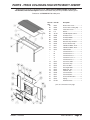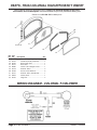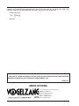
1
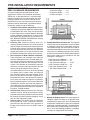
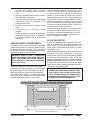
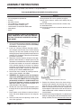
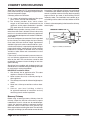
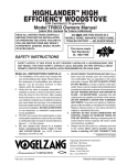
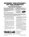
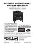
Colonial™ High Efficiency
Fireplace Insert
EPA Certified (4.02grams/hr)
Model TR004 Owners Manual
(save this manual for future reference)
This appliance meets U.S. Test
Standard: UL 1482-2006
Do NOT use this appliance in a
mobile home, Manufactured Home,
trailer, or TENT – NO EXCEPTIONS!
READ ALL INSTRUCTIONS CAREFULLY
BEFORE STARTING THE INSTALLATION
of OR OPERATING this Appliance.
Failure to follow instructions
may result in property damage,
bodily injury, or even death.
Refer to markings on
STOVE labels for
additional information.
Vogelzang International Corporation
400 West 17th Street
Holland, Michigan 49423
www.vogelzang.com
Phone: 1-616-396-1911
Fax: 1-616-396-1971
TR004M | 11102010.0
TR004 COLONIAL™ |
Page 1
SAFETY INSTRUCTIONS
Safety Notice: If this appliance is not properly installed a house/building
fire may result. For your safety, contact local building or fire officials about
permits, restrictions, and installation requirements for your area.
Read All Instructions carefully.
1. The installation of this insert must comply with your
local building code rulings.
2. Do not install this appliance in a mobile
home, manufactured home, trailer or
tent (NO EXCEPTIONS! per HUD Federal
Standard: 24 CFR Ch.XX).
3. Verify that the insert is properly installed before
firing the appliance for the first time. After reading
these instructions, if you have any doubt about
your ability to complete your installation properly,
you must obtain the services of a professional
licensed installer familiar with all aspects of safe
and correct installation. DO NOT use temporary or
makeshift compromises during installation.
4. If any parts are missing or defective, please notify
the dealer or manufacturer immediately. DO NOT
OPERATE An insert THAT IS MISSING ANY
PARTS!
5. Warning: Risk of fire. Observe the minimum
clearances to combustibles (see figures 1–3). Do
not place furniture, rugs, carpet or other objects
within the clearance area.
6. Warning: Risk of fire. DO NOT store wood,
flammable liquids or other combustible materials
within minimum clearance dimensions. Refer to
certification label on unit and reference figures 1 – 3
in this manual.
7. Do not tamper with combustion air control beyond
normal adjustment capacities.
8. Always connect this insert to a chimney and vent
to the outside. Never vent to another room, crawlspace, or inside a building. DO NOT CONNECT
THIS UNIT TO A CHIMNEY FLUE SERVING ANOTHER APPLIANCE.
9. DO NOT connect a wood burning appliance to an
aluminum Type B gas vent. This is not safe. Use
approved masonry or a UL 103 HT (U.S) Listed
Residential Type and Building Heating Appliance
Chimney. Use a 6” diameter chimney, that is high
enough to give a good draft.
10. Be sure that your chimney is safely constructed
and in good repair. Have the chimney inspected
by the fire department or a qualified inspector. Your
insurance company should be able to recommend
a qualified inspector.
11. Creosote or soot may build up in the chimney liner
and chimney and cause a house/building fire. Inspect the chimney liner and chimney twice monthly
during the heating season and clean if necessary.
Page 2 | TR004 COLONIAL™
(See Chimney Maintenance, page 12).
12. In the event of a chimney fire, turn the air
control to closed position, leave the building and CALL THE FIRE DEPARTMENT
IMMEDIATELY! Have a clearly understood plan
on how to handle a chimney fire by contacting your
local or provincial fire authority for information on
proper procedures in the event of a chimney fire.
13. To prevent injury, do not allow anyone to use this
appliance who is unfamiliar with the correct operation of the appliance.
14. Do not operate appliance while under the
influence of drugs or alcohol.
15. For further information on using your insert
safely, obtain a copy of the National Fire
Protection Association (NFPA) publication, “Using
Coal and Wood Stoves Safely” NFPA No. HS-101978. The address of the NFPA is Batterymarch
Park, Quincy, MA 02269.
16. Ashes should not be allowed to accumulate more
than an inch or two in height. Dispose of ashes in
a metal container with a tight fitting lid. Keep the
closed container on a noncombustible floor or on
the ground, well away from all combustible materials. Keep the ashes in the closed container until
all cinders have thoroughly cooled. The ashes may
be buried in the ground or picked up by a refuse
collector.
17. The paint used on your insert may give off smoke and/
or odor during the first fires. This may occur during
the first 12 to 15 fires until the paint has cured. After
the paint has cured this will end and not reoccur. Persons with lung conditions or owners of susceptible
domestic pets (such as birds) should take
prudent precautions. Open windows and doors as
needed to clear smoke and odor. If the insert is
overfired, paint discoloration will occur.
18. This inser t has a painted surface which
is durable but it will not stand rough handling
or abuse. When installing your insert, use care
in handling. Clean with soap and warm water
when insert is not hot. Do not use any acids
or scouring soap, as these solvents wear and dull
the finish.
19. The walls of the firebox may become slightly distorted after a period of use. A slight distortion will
not affect the operation of the insert.
20. CAUTION: Hot Surfaces. Do not touch during
operation. While appliance is in operation, all percontinued on next page
TR004M | 11102010.0
SAFETY INSTRUCTIONS continued…
sons, especially young children should be alerted
to the hazards from high surface temperatures.
Keep away from a hot appliance to avoid burns or
clothing ignition.
21. CAUTION: Hot Surfaces. Keep children
away. If small children will be in the same room
as the appliance during operation, provide a
sturdy barrier to keep them at a safe distance
from the inser t. Never leave small
children unsupervised when they are
in the same room as the appliance.
22. Keep area around the appliance clear and free
from all combustible materials, gasoline, and other
flammable vapors and liquids.
23. To prevent bur ns always wear protective
clothing, leather hear th gloves and eye
protection.
24. Warning: Risk of fire. While in operation,
keep the feed door closed and secured at all times
except while tending the fire.
25. Do not over fire the inser t. Over firing will
occur if the feed door is left open during
operation. Such actions can result in very
dangerous operating conditions.
26. DO NOT ELEVATE FIRE! Build fire directly on the
bottom of the firebox. This appliance has not been
tested with the use of grates, andirons, or other
means of elevating fire and should not be used.
27. All power cords and electrical appliances
and/or assemblies must be kept outside of the
clearance dimensions shown in this manual for
combustible materials.
TR004M | 11102010.0
NOTE: A professional, licensed heating and cooling contractor should
be consulted if you have questions
regarding the installation of this
solid fuel burning appliance.
TR004 COLONIAL™ |
Page 3
Table of Contents
Safety Precautions......................................................................................... 2 – 3
Product Dimensions............................................................................................ 5
Pre-installation Requirements............................................................................ 6
Chimney Condition ..................................................................................... 6
Minimum Clearances to Combustible Materials ....................................... 6
Venting ......................................................................................................... 7
Floor Protector ............................................................................................ 7
Tools and Materials Required for Installation.................................................... 8
Assembly Instructions Chimney Connection . ................................................. 8
Chimney Connection ................................................................................ 9
Faceplate Assembly . ................................................................................ 9
Firebrick Assembly ................................................................................... 9
Chimney Connections/Draft.............................................................................. 10
Operating Instructions
House Fire Hazards, Operating Precautions, Warnings....................... 11
Wood Types/Sizes..................................................................................... 11
Optimal Fuel Consumption..................................................................... 11
Starting a Fire, Adding Fuel.................................................................... 12
Blower Operation.................................................................................... 13
Service Hints
Creosote Formation, Prevention, Removal . ......................................... 13
Chimney Draft ......................................................................................... 13
Glass Care & Replacement, Glass Gasket Replacement .................... 14
Parts – Colonial™ ............................................................................................. 15
Parts – Glass Door (Glass Replacement)........................................................ 16
F-5 Blower Wiring Diagram................................................................................ 16
Floor Protector Calculations............................................................................. 17
Page 4 | TR004 COLONIAL™
TR004M | 11102010.0
Colonial™ dimensions
TR004M | 11102010.0
TR004 COLONIAL™ |
Page 5
Pre-Installation Requirements
Fireplace condition &
Zero Clearance Requirements
A masonry fireplace must meet minimum code
requirements, National Fire Protection Association,
(NFPA) 211, or the equivalent for a safe installation.
Contact a professional, licensed installer, your local
building inspector or the local fire authority for the
requirements in your area. Your insurance company
should be able to recommend a quallified inspector.
Inspections should include the following:
1. Condition of the fireplace and chimney. A masonry fireplace and chimney MUST be inspected prior
to installation of this insert. They must be free from
cracks, loose mortar, creosote deposits, blockage
or other evidence of deterioration. If found, these
items MUST be repaired prior to installation. DO
NOT REMOVE BRICKS or MORTAR from existing
fireplace when installing this unit.
2. Chimney Size. Minimum chimney size is 6˝
(152mm) diameter. Maintain a 15 ft. minimum overall
chimney height measured from the top of appliance
to the top of the chimney. Chimneys must extend at
least 3 ft. above the roof and at least 2 ft. above the
highest point within 10 ft. of the chimney top. See
the Chimney Connections section of this manual.
2. Zero Clearance or Metal Heatform Fireplaces.
These fireplaces and chimneys must meet the
minimum code specifications as noted above. Factory built zero clearance fireplaces must be listed
and suitable for solid fuel use. Chimneys must be
at least 7 inch diameter to accomodate a required,
continuous, stainless steel liner from the insert flue
collar to the top termination of the chimney.
Only detachable parts that can be easily replaced
(i.e. damper parts, screens, doors and side and
back refractory panels) are to be removed. These
parts must be stored and readily available for replacement if the insert is ever removed. The removal
of any parts that render the fireplace unusable for
burning solid fuel requires a permanent label to be
affixed by the installer that states the fireplace is
unsuitable for burning solid fuel unless the missing
parts are replaced and the fireplace is restored to
its original, certified condition.
3. Chimney Caps. Mesh type chimney caps and spark
arrestors must be able to be removed for regular
inspection and cleaning. Otherwise the mesh should
be removed to prevent possible plugging. Check
your local fire and building codes.
4. Chimney Liner. The chimney must be suitable for
burning solid fuel. Install a continuous stainless
steel liner from the flue collar of the appliance to
the top of the chimney. Liner must be UL Listed to
UL1777.
Page 6 | TR004 COLONIAL™
5. Fireplace Opening Dimensions.
A. Minimum Height...........23˝
B. Minimum Widths...........29˝
C. Minimum Depth............14˝
Figure 1 Minimum Opening Specifications
6. Combustible Material Clearances. The fireplace
and chimney must be inspected to make sure there
is adequate clearance to combustible materials.
This includes the top, side, front and back as well as
concealed combustibles in the chimney and mantle
areas. Your local building inspector or fire authority
should have information on whether older fireplace
meet current codes and are suitable for use. See
also figure 1 and figure 2.
D. Min. Distance to Sidewall.........12˝
E. Min. Distance to Top Trim.........15˝
F. Min. Distance to Mantle...........21.75˝
G. Min. Distance to Side Trim.......9.5˝
H. Min. Floor Protector Front........24˝
I. Min. Floor Protector Side.........6˝
Figure 2 Minimum Clearance to Combustible Materials
7. Makeup Air Requirements. This insert requires an
adequate supply of makeup air to operate safely
and efficiently. In some areas, this is a building code
requirement. Inadequate air supply will cause poor
combustion, inefficient operation, creosote buildup,
back drafting and smoke puffing into the living areas. If any of the following conditions are evident,
a makeup air supply MUST be installed.
TR004M | 11102010.0
a. Existing fuel-fired equipment show evidence
of back puffing, smoke roll-out, inefficient
operation or excessive smell in the living
area.
b. Opening a window or door alleviates any of the
above problems or symptoms.
c. The building is constructed with a well-sealed
vapor barrier, tight fitting windows or has
powered exhaust fans.
d. Excessive condensation on windows in the
winter.
e. The building has a ventilation system
installed.
f. If, once installed, the solid-fuel appliance does
not draw steadily, burns poorly or inefficiently,
back-drafts or experiences back-puffing when
adding fuel.
Venting (Draft) Requirements
The chimney flue is a critical component to the proper
and efficient operation of any heating appliance. Heating appliances do not create draft, draft is provided by
the chimney. This appliance requires a draft of 0.05 in.
water column (0.1 Pa) at the flue collar.
Warning: Risk of Fire - Excessive
draft can cause over firing and possible structure fire. Do not operate
appliance with flue draft exceeding
0.06 in. w.c. (0.1 Pa).
To achieve proper draft, your chimney must meet
three minimum height requirements; minimum height
from top of appliance (15 ft. total height from top of
appliance), minimum height above roof penetration
(3 ft.), and minimum height (2 ft.) above highest point
of roof within a 10 ft. diameter from the chimney. See
Chimney Connections section of this manual.
The chimney must also meet minimum and maximum
cross sectional requirements. For that reason a continuous 6˝ stainless steel liner from the flue collar to
the top of the chimney is required. A stainless steel
adapter is recommended for fastening the stainless
steel liner to the flue collar. The male (or crimped) end
of the adapter must be installed inside the flue collar
to allow condensation or creosote in the liner to drain
back into the firebox. Chimney liners and/or adapters
must be permanently fastened using a minimum of
three (3) screws at each connection.
Chimneys outside of the home or on an exterior wall
are difficult to keep at operating temperatures and
may result in increased creosote buildup, less draft,
back drafting problems and poor appliance performance and should be avoided.
Floor Protector
A solid non-combustible floor, concrete or solid masonry must extend 6˝ to either side of the body of the
insert and 24˝ in front of the face of the insert. This
would require a floor protector 38˝ wide by 24˝ deep.
(See figures 2 & 3)
When combustible flooring falls within these minimum
dimensions, it must be covered with a listed floor
protector such as Hy-C or Imperial Model UL 2840BK
or equivalant with 0.84 R-factor. (Note: to calculate
R-value of alternative materials see Floor Protector
Material Calculations at the back of this manual.)
A grouted ceramic floor tile that meets local building
codes and the minimum 0.84 R-factor requirements is
considered a durable equivalent.
Warning: Risk of Fire. Do not allow
combustible materials (carpet, furniture, fuels) to be placed on or cover
the floor protector. All combustible
materials must remain outside of the
minimum clearance dimensions.
Figure 3 Floor Protector Specifications
TR004M | 11102010.0
TR004 COLONIAL™ |
Page 7
Assembly Instructions
NOTICE: Vogelzang International Corp. grants no warranty, stated or implied, for the installation or maintenance of your wood
stove and assumes no responsibility of any incidental or consequential damages.
Tools and Materials Required for Installation
•
•
•
•
•
•
•
•
•
tools
Pencil
6 foot Folding Rule or Tape Measure
Tin Snips
Drill: Hand or Electric
1/8” dia. Drill Bit (for sheet metal screws)
Screwdrivers (blade and Phillips type)
14mm Nut Driver or Ratchet with 14mm Socket
Safety Glasses
Gloves
materials
(NOTE: The following items are not included with your stove)
Flooring Protection: 24” x 38” as specified (see page 5)
Chimney Liner: Continuous stainless steel chimney liner (as
required)
Stainless Steel Adapter (connects the liner to the flue collar)
1/2” Sheet Metal Screws
Furnace Cement (manufacturer recommends Rutland Code 78
or equivalent)
CAUTION: INSERT is heavy. Make sure you
have adequate help and use proper
lifting techniques whenever moving
the insert.
1. Clean the fireplace opening properly disposing of
any ashes in a closed metal container. See Safety
Instructions, #16 on page 2.
2. Install a 6˝ (152mm) minimum diameter, continuous stainless steel chimney liner into the existing
chimney. The liner must extend to the top of the
existing chimney. Use only listed chimney liners that
meet UL1777 standards. Follow liner manufacturer
installation instructions.
3. Remove or lock the fireplace damper in the open
position. Note: Masonry or damper plate may be
removed to accomodate the chimney liner provided
this does not weaken any structural components
of the existing fireplace or chimney nor reduces
protection of combustible materials required by
national building codes. Consult with your local
building or fire authority before doing this.
4. Uncrate the insert, remove all packing materials,
and any items stored in the firebox.
5. WARNING: Any fireplace which has had parts
removed or modified to accomodate the installation of this insert MUST have a warning plate
permanently installed in a visible location stating that the fireplace is unfit for use with solid
fuel. Permanently attach the warning plate to a
visible location in the fireplace.
6. Position the insert into the fireplace opening until
the top lip of the air jacket is flush with the fireplace
facing.
7. Direct power cord of blower to desired side of
insert and attach blower to front of unit using two
screws.
8. Level the insert with the adjusting screws at the
rear of the appliance.
Page 8 | TR004 COLONIAL™
Fig. 4– Stainless Steel Liner Connection
9. Connect the chimney liner to the insert using a
stainless steel adapter and securing with a minimum of three (3) sheet metal screws. The liner
MUST be attached with the male (or crimped) end
of the adapter inside the flue collar of the insert to
allow condensation and/or creosote to drain back
into the firebox.
10. Assemble the face plate (figure 5). Lay pieces face
down on carpet or other soft surface to protect finish
during assembly. The face plate consists of two side
Continued on next page
TR004M | 11102010.0
panels, a top panel and a decorative trim frame.
11. Bolt the top panel (1) to the side panels (2) so the
top surfaces are flush to one another.
12. Assemble the trim frame. The trim consists of a left
(7) and right (4) side piece and a split top piece
(left #6, right #5). These are joined by two corner
connectors (8) and a straight center connector (9).
These slide into the channel on the back of the
frame and are secured with two set screws (10) in
each piece.
15. The faceplate assembly is held in place with two
springs at the top of either corner of the insert
(figure 6).
16. Connect power cord of blower to grounded receptacle.
17. Firebrick extends the life of your stove and radiates heat more evenly. If firebricks were removed
to position insert replace them before firing insert.
See figure 7 for proper orientation and positioning.
Install the back row first, then sides and finally install
bottom firebricks.
CAUTION: RISK of Fire.
• REPLACE FIREBRICKS Before firing
woodstove. Position firebricks so no
gaps remain between bricks.
• Never operate appliance with missing
or cracked fire bricks.
• Keep furnishings and other combustible materials away from the stove
AND OUTSIDE Minimum Clearances.
Figure 5 – Face
Plate Assembly
A
A
A
A
A
Fire Brick Dimensions
A-Size: 9˝ x 41/2˝
M-Size: 9˝ x 21/4˝
R-Size: 9˝ x 33/8˝
S-Size: 11/4˝ x 21/4˝
T-Size: 9˝ x 31/3˝
Five (5) A-Size
Note: All fire brick
are 11/4˝ thick
Figure 7a – Step 1, Back
Firebrick Arrangement
Six (6) T-Size
T
TR004M | 11102010.0
A T
M
A
A
T
T
R
T
A
A
S
A
A
T
Figure 7b– Step 2,
Side Firebrick Arrangement
T
T
A
Figure 6 – Face
Plate Installation
T
A
A
T
A
A
A T
A
R
13. The trim slides over the face panel assembly and
is secured at the base of each side with a machine
screw (11).
14. The Faceplate Assembly is then slid over the insert.
Slots in the two side panels accomodate the hood
at the top of the insert (figure 6).
T
Four (4) A-Size
One (1) M-Size
Two (2) R-Size
One (1) S-Size
Figure 7c– Step 3,
Bottom Firebrick Arrangement
TR004 COLONIAL™ |
Page 9
Chimney Specifications
This appliance must be connected to a listed Stainless
Steel Liner, that meets UL1777, which extends from the
collar to the chimney cap according to the specifications
listed on the previous pages.
Chimneys perform two functions:
1). As a means of exhausting smoke and flue gases
which are the result of fuel combustion.
2). The chimney provides “draft,” which allows
oxygen to be continuously introduced into the
appliance, so that proper combustion is possible.
This stove relies on natural draft to operate.
NOTICE: Always provide a source of fresh air into the
room where the stove is located. Failure to do so may
result in air starvation of other fuel burning appliances
and the possible development of hazardous conditions,
fire or death.
Your insert itself does not create draft. Draft is provided
by the chimney. To achieve proper draft your chimney
must meet the three minimum height requirements
detailed in figure 8. A minimum draft of 0.05 w.c. (measured in water column) is required for proper drafting to
prevent back puffing, smoke spillage, and to maximize
performance. (Gauges to measure draft are readily
available at stove stores and are economical to rent
or purchase.)
Factors such as wind, barometric pressure, trees, terrain and chimney temperature can have an adverse
effect on the draft. The manufacturer cannot be held
responsible for external factors leading to less than
optimal drafting.
Should you have a problem with inadequate draft, you
should contact a licensed heating and cooling contractor
for assistance in solving the problem.
IMPORTANT Installation Points
1. Size chimney flue to appliance collar. This stove
requires a minimum 6” diameter flue.
2. Never connect this unit to a chimney serving another appliance.
3. The chimney must meet all minimum height requirements.
4. Never use a chimney to ventilate a cellar or basement.
5. C o n t a c t y o u r l o c a l b u i l d i n g a u t h o r i t y
for approved methods of installation and any
necessary permits and/or inspections.
to a masonry chimney are detailed in the installation
instructions. If the fireplace chimney must go through
a combustible wall before entering the main chimney,
consult a qualified mason or chimney dealer regarding
proper materials that meet all local building and fire
authourity codes. The installation must conform to local building and fire codes and latest edition of NFPA
211.
If there is a cleanout opening in the base of the chimney,
close it tightly.
Figure 8 - Chimney Construction
Masonry Chimney
Before using an existing masonry chimney, clean the
chimney, inspect the flue liner and make any repairs
needed to be sure it is safe to use. As mentioned previously, this appliance requires a continuous stainless
steel liner from the insert collar to the chimney cap.
Make repairs before attaching the stove. The connector
stove pipe and fittings you will need to connect directly
Page 10 | TR004 COLONIAL™
TR004M | 11102010.0
Operating Instructions
CAUTION: HOUSE FIRE HAZARDS
This appliance is designed to burn
WOOD FUEL ONLY!
• Do not store wood on floor protector, underneath stovepipe(s) if applicable, or anywhere within minimum
clearances from combustible surfaces specified for this appliance.
Hardwood, 17” to 19”, should be split and air dried
(seasoned) for 6 months to obtain maximum burning efficiency. Wood should be stored in a dry, well ventilated
area.
•Overfiring may cause a house fire.
You are overfiring If a unit glows
Red.
NOTICE: Use solid wood materials only.
Do Not burn garbage or flammable
fluids. Do Not Use Coal. This INSERT is
not designed to accommodate the air
flow (draft) necessary to properly
burn coal or coal products. Do not
elevate fire or use grates or andirons. Build fire directly on bottom
of firebox.
Operating Safety Precautions
1. Never overfire this appliance by
building excessively hot fires as a
house/building fire may result. You
are overfiring the appliance if it
begins to glow or turn red.
2. Never build extremely large fires
in this type of applianace as damage
to the firebox or smoke leakage may
result
3. Do not build fire too close to
glass.
4. Unit is HOT while in operation. Keep
children, clothing, and Furniture away.
Contact may cause skin burns. Do not
touch the appliance after firing until
it has cooled.
5.Provide air into the room for proper
combustion.
6. Inspect chimney liner every 60 days.
Replace immediately if liner is rusting
or leaking smoke into the room.
WARNING: Explosion Hazard
• Never use chemicals, gasoline,
gasoline-type lantern fuel, kerosene,
charcoal lighter fluid, or similar
flammable liquids to start or “freshen-up” a fire in the stove.
• K eep all flammable li q u ids ,
especially gasoline, out of the
vicinity of the stove— whether in use
or in storage.
OPTIMAL FUEL CONSUMPTION
This insert is designed to get the most efficient
transfer of heat energy from the wood fuel and radiate
it into your living environment. The fire box introduces
combustion air through three sources; (1) Immediately
beneath the door opening below the window is a Lower
Primary Air Orifice (LPAO), (2) The door air inlet control brings air into the firebox and controls the rate of
burn (and the amount of heat the insert radiates), (3)
The secondary air tubes at the top of the firebox are
designed to ignite the combustion gases (smoke) given
off by the burning wood and increases the efficiency of
the insert and reduces chimney emissions.
Smoke given off by burning fuel consists of very
small organic liquid droplets. If these droplets condense,
they form a sticky tar-like substance called creosote.
When operated properly, this insert is designed to burn
these droplets. Burning these droplets releases heat
that would otherwise be lost up the chimney as smoke.
Following the instructions below will help you operate
your insert properly to maximize the insert’s performance. Actual performance is dependent on chimney
height, weather, log size, wood species and moisture
content. Some experimentation will initially be required
to find that “sweet spot” where your insert performs best.
The following will give you a starting point to find your
optimum settings.
When first loading fuel, set the door air inlet control
at the wide open position for at least 15–20 minutes.
When the insert is working properly you should be able
to observe secondary combustion flames above the fuel
pieces in front of the secondary air tubes at the top of
the firebox. These secondary flames should continue to
burn after the primary air inlet is reset from wide open
to the desired operating setting. If the flames do not
continue to burn, open the air control to re-establish the
Continued on next page
TR004M | 11102010.0
TR004 COLONIAL™ |
Page 11
Operating Instructions continued . . .
secondary flames then slowly reset the air control to the
desired setting. Initially it may take several attempts to
figure your insert out. But once you find the operating
“sweet spot” and the correct mix of procedures to get
there, only minor adjustments will be necessary.
The best indicator of a properly operating insert is
to look for smoke coming out of the chimney. You may
see steam emissions that will quickly dissipate. Smoke
will thin but continue to drift without totally disappearing.
If you do detect smoke emissions, open the air control
a little bit, let the insert adjust for 10–15 minutes and
re-check your chimney. Remember – visible smoke
represents lost heat.
NOTICE - INITIAL BURNS to Cure PAINT.
Because of the high operating
temperatures, this insert uses
a special high-temp paint which
requires a series of burns to
cure the paint for durability and
a lifetime of service.
Proper curing of the high-temp paint
requires a series of three initial burns. The insert
should be allowed to cool off between each burn.
The first two burns should be small fires and low
temperatures (250 degrees F) for a duration of
20 minutes each. The third fire should be at a
medium-high temperature (500 F to 700 F) for 20 minutes. Provide adequate cross ventilation to clear any
smoke or odor caused by initial firings.
STARTING a Fire
1. Set air inlet control to fully open position.
2. Open the door and place several wads of crushed
paper in the firebox.
3. Cover the paper with a generous amount of kindling in a teepee fashion and a few small pieces of
wood.
4. Ignite the paper and leave the door open slightly.
DO NOT LEAVE Insert UNATTENDED WITH
DOOR OPEN!
5. Add large pieces of wood as the fire progresses
being careful not to overload. (Do not fill firebox
beyond firebrick area.) An ideal coal bed of 1 – 2”
should be established to achieve optimum performance.
6. This unit is designed to function most effectively
when air is allowed to circulate to all areas of the
firebox. TIP: If ash or coals remain in the insert,
make sure to clear them away from the Lower Primary Air Orifice (LPAO) and rake a slight (1-to-2
inch wide) trough down the center of the coal bed
from front to back prior to loading the fuel.
Page 12 | TR004 COLONIAL™
7. Once fuel has been loaded, close the door and
leave the air inlet control fully open until fire is well
established (at least 15–20 minutes) being careful
not to over fire (if any of the exterior parts of the
insert or chimney connections begin to glow you
are over firing the insert).
8. Re-adjust the door air inlet control to desired burn
rate. (If excessive smoke fills the firebox, open air
inlet control slightly until flames resume and wood
is sufficiently ignited.) The basic rule of thumb is
“closed - low,” “half way open - medium” and “fully
open - high.”
Adding Fuel
If the coal bed is not hot and glowing, rake the coals
to the front of the insert, close the door and adjust the air
inlet control to the wide open position. Let the coals reheat for 10–15 minutes. When hot and glowing, spread
them out and place your next fuel load into the insert
(make sure no coals or ashes block the LPAO). Leave
the door air inlet control in the wide open position for
15–20 minutes.
Fuel load size can vary but should be kept 1–2
inches below the secondary air tubes. Also position the
fuel to leave space so the air from the inlet can work
down between the pieces of fuel. This reduces the time
it takes for new fuel to burn properly.
1. When refueling, adjust air inlet control to the fully
open position. When fire brightens, slowly and
carefully open the door. This procedure will prevent
gases from igniting causing smoke and flame spillage.
2. Add fuel being careful not to overload or overfire
the insert.
3. When adding fuel be careful not to smother the fire.
Do not build fires against glass and make sure the
coal bed does not obstruct the air inlet.
4. Close the feed door and secure tightly.
5. Adjust the air inlet control as described above.
6. Empty ashes regularly. Do not allow ashes
to pile up (see Safety Instructions #16 on
page 2.)
7. Properly dispose of hot ashes (see Safety
Instructions, item #16 on page 2.)
8. Do not overfire the insert (overfiring is when
any par t of the inser t exterior or chimney
connections glow).
CAUTION: DO NOT OVERFIRE appliance.
You are overfiring if any part of the
insert glows red. Close the door and
shut damper immediately to reduce the
air supply and slow down the fire.
TR004M | 11102010.0
Operating continued . . . Chimney Maintenance
Blower Operation
The variable speed blower circulates air warmed by the
firebox into the living area to distribute the heat more
evenly. The blower control knob is located on the side
of the blower housing.
Turn the knob clockwise to turn the blower on. The
speed is controlled by turning the knob clockwise for
slower speeds and counter-clockwise for faster speeds.
To turn the blower off, turn the speed control knob fully
counter-clockwise. It is recommended to turn the blower
off when the unit is not in operation.
Chimney Maintenance
CAUTION: Slow burning fires and
extended use m ay cause exces sive creosote buildup. Ignition of
creosote or over firing may cause
A chimney fire. Chimney fires burn
extremely hot and may ignite surrounding materials. In case of a
chimney fire call the fire department
immediately.
CREOSOTE – Formation and Removal
When wood is burned slowly, it produces tar and other
organic vapors which combine with expelled moisture
to form creosote. The creosote vapors condense in the
relatively cool chimney flue of a slow-burning fire and
can accumulate on the flue lining. If ignited, this creates
an extremely hot fire in the chimney which may ignite
surrounding materials resulting in a building fire.
The chimney connector and chimney should be inspected (at least) twice a month during the heating season
to determine if a creosote buildup has occurred. If it
has, it should be removed. Failure to remove creosote
may result in ignition and may cause a house/building
fire. Creosote may be removed using a chimney brush
or other commonly available materials from your local
hardware retailer.
Chimney fires burn very hot. If the unit or chimney
connector should glow red, reduce the fire by closing the inlet air control and immediately call the fire
department.
CAUTION: A chimney fire may cause ignition of wall studs or rafters which
were assumed to be a safe distance
from the chimney. If a chimney fire
has occurred, have your chimney inspected by a qualified Expert before
using again.
A fire in the firebox may be smothered by pouring a
large quantity of coarse salt, baking soda, or cool ashes
on top of the fire.
TR004M | 11102010.0
Preventing Creosote Buildup
1. Burn with air control open for several minutes at
numerous intervals throughout the day during the
heating season, being careful not to overfire the
unit.
2. Burn insert with air inlet control wide open for 15–20
minutes every time you apply fresh wood. This
allows wood to achieve the charcoal stage faster
and burns wood vapors which might otherwise be
deposited within the heating system.
3. BURN ONLY SEASONED WOOD. Avoid burning
wet or green wood. Seasoned wood has been dried
for at least one year.
4. A small hot fire is preferable to a large smoldering
one that can deposit creosote within the heating
system.
5. Establish a routine for the handling of fuel, wood
burner and firing technique. Check daily for creosote buildup until experience shows how often you
need to clean for safe operation. Be aware that the
hotter the fire, the less creosote is deposited, and
weekly cleanings may be necessary in mild weather
even though monthly cleanings may be enough in
colder months.
WARNING: In case of chimney fire;
(1) Close air inlet control, (2) Get
out of the house, (3) Call the fire
department.
Chimney Draft
NOTE: A draft reading of 0.05 to 0.06 w.c.
(water column) is required for proper
burning of this insert.
Draft is a function of the chimney, not the
insert — do not expect the insert to draw. Smoke spillage into the house or excess buildup of condensation or
creosote in the chimney are warnings that the chimney
is NOT functioning properly. Correct the problem before
using the insert. Following are some possible causes
for improper draft.
1. The connector insert pipe may be pushed into the
chimney too far, stopping the draft.
2. If the chimney is operating too cool, water will condense in the chimney and run back into the insert.
Creosote formation will be rapid and may block
the chimney. Operate the insert at a fire level high
enough to keep the chimney warm preventing this
condensation.
3. If the fire burns well but sometimes creates excessive smoke or burns slowly, it may be caused by
the chimney top being lower than another part of
the house or a nearby tree. The wind blowing over a
Continued on next page
TR004 COLONIAL™ |
Page 13
Service Hints
house or tree falls on top of the chimney like water
over a dam, beating down the smoke. The top of
the chimney should be at least three (3) feet above
the roof and be at least two (2) feet higher than any
point of the roof within ten (10) feet.
Glass Care
The following usage and safety tips should be observed:
1. Inspect the glass regularly for cracks and breaks.
If you detect a crack or break, extinguish the fire
immediately and contact the manufacturer for a
replacement.
2. Do not slam the door or otherwise impact the glass.
When closing doors, make sure that logs or other
objects do not protrude to impact the glass.
3. Do not build fires against (or that might fall against)
the glass.
4. Do not clean the glass with materials that may
scratch (or otherwise damage) the glass. Scratches
on the glass can develop into cracks or breaks during operation.
5. Never attempt to clean the glass while the unit is
hot. If deposits are not very heavy, normal glass
cleaners are adequate using a soft, non-abrasive
cleaning pad. Heavier deposits may be removed
with oven cleaners.
6. Never put substances which can ignite explosively
in the unit. Even small explosions in confined areas
can blow out the glass.
6. Trim to length and butt ends together.
7. Replace glass into door, being sure not to overtighten screw and clip.
After extensive use, the gasket material which provides
glass and door seal may lose it’s resiliency and will
need to be replaced. Inspect glass and door gaskets
periodically to ensure proper seal; if gaskets become
frayed or worn, replace immediately.
Door Gasket Replacement Procedure:
1. Ensure appliance is not in operation and is
thoroughly cooled.
2. Remove old door gasket and clean channel.
3. Using an approved, high temperature gasket
cement, apply a thin coat in bottom of channel.
4. Starting at hinge side of door, work gasket into
channel around door unit, end butt and trim to
length.
5. Close door and allow three to four hours for cement
to set before firing appliance.
Gasket and Glass cleaning products are available at
local retail home centers. Manufacturers of cleaning
products for wood stoves include, A.W. Perkins Co.
(www.awperkins.com) or Rutland Products (www.
rutland.com).
Glass Replacement
Caution: Replace glass ONLY with 5mm High
Temperature ceramic glass of the proper size.
Do not use tempered glass or double thickness window glass!
Glass Replacement Procedure:
1. Ensure appliance is not in operation and is thoroughly cooled.
2. Remove screw and glass clip. (See parts list and
diagram.)
3. Lift glass out from glass clip.
4. Remove old gasket and clean glass.
5. Replace new gasket starting at the bottom of glass
working along edges, being sure to center gasket
channel on glass.
Page 14 | TR004 COLONIAL™
TR004M | 11102010.0
Parts - TR004 Colonian High-Efficiency Insert
When ordering missing or replacement parts, always give the Model Number of the insert,
Part Number, and Part Description. Use the illustrations and part lists provided to identify parts.
Contact us at 616-396-1911 to order parts.
Ref. No.
Qty.
01
02
03
04
05
06
07
08
09
10
11
12
13
–
–
–
–
–
14
15
16
17
18
19
20
21
22
23
34
TR004M | 11102010.0
Part No.
Dscription 04-01
04-02
04-03
F-5
SC-01
04-06
04-07
04-08
04-09
04-10
04-11
04-12
04-13
A
M
R
S
T
04-14
04-15
04-16
04-17
04-18
04-19
04-20
04-21
04-22
04-23
HP-04
Draft Control Lever.................. 1
Screw, Rear Leveling Adj........ 2
Intake Vent Cover.................... 1
Blower..................................... 1
Variable Speed Control........... 1
Air Tube, Front......................... 1
Air Tube, Middle...................... 1
Air Tube, Rear......................... 1
Retainer Clip, Air Tubes.......... 3
Screw, Retainer Clip............... 3
Fiberboard Baffle, Front.......... 1
Fiberboard Baffle, Rear........... 1
Fiber Blanket........................... 1
Fire Brick 9˝x 4 ¹⁄2˝................... 5
Fire Brick 9˝x 2 ¹⁄4˝................... 1
Fire Brick 9˝x 3 ³⁄8˝................... 2
Fire Brick 1¹⁄4˝x 2 ¹⁄4˝................ 1
Fire Brick 9˝x 3 ¹⁄3˝................... 6
Face Plate, Side...................... 2
Face Plate, Top....................... 2
Trim, Left Side......................... 1
Trim, Right Side....................... 1
Right Trim, Top........................ 1
Left Trim, Top........................... 1
Corner Bracket........................ 2
Center Bracket........................ 1
Screw, Trim Brackets............... 6
Spring..................................... 2
Hardware Pack........................ 1
parts list continued on next page
TR004 COLONIAL™ |
Page 15
Parts - TR004 Colonial High-Efficiency Insert
When ordering missing or replacement parts, always give the Model Number of the insert,
Part Number, and Part Description. Use the illustrations and part lists provided to identify parts.
Contact us at 616-396-1911 to order parts.
33
30
31
24, 25, 26
27
28
29
32
Ref.
No.
24
25
26
27
28
29
30
31
32
33
Part
No.
DescriptionQty.
04-24
Door Assembly (complete)..................... 1
04-25
Handle Assembly (complete).............. 1
04-26
Door Frame (only)............................... 1
04-27
Door Glass.......................................... 1
WG01
Gasket, 7/8˝ Fiberglass Glass............. 1
04-29
Retainer, Glass.................................... 5
04-30
Screws, Glass Retainer....................... 8
04-31
Retainer, Glass, Handle Side.............. 1
GK34
Gasket, Door....................................... 1
04-33
Hinge Pin............................................. 2
Wiring Diagram - Colonial F-5 Blower
Page 16 | TR004 COLONIAL™
TR004M | 11102010.0
Floor Protector Material Calculations
This stove has been tested for and must be installed on a floor protector with the proper Thermal Resistance or R-value
as stated in the installation instructions on page 3, “Locating Stove” step 1, of this manual. If the floor protector materials
listed in the instructions are not available, materials with an equivalent R-value may be substituted.
Alternate materials may be rated with C-factor (Thermal Conductance) or k-factor (Thermal Conductivity) ratings which
must be converted to R-value to determine if the alternate material meets the tested requirements. The following instructions
provide the proper information and formulas for conversion to R-value.
To determine if alternate materials are acceptable follow this sequence.
1. Convert material specifications to R-value:
a. R-value given — no conversion necessary
b. k-factor is given with a required thickness (T) in inches:
R = 1/k x T
c. C-factor is given: R = 1/C
2. Determine the R-value of proposed alternate floor protector:
a. Use formulas in step 1 above to calculate R-value of proposed material(s).
b. For multiple layers, add R-values of each layer to determine overall R-value.
3. If the overall R-value of the floor protector system is equal to or greater than the floor protector specifications given,
the alternate is acceptable.
Definitions:
Thermal conductance (C) = BTU
=
2
(hr)(ft )(°F)
W
(m )(°K)
Thermal conductivity (k) =
(Btu)(inch)
=
(hr)(ft2)(°F)
W
=
(m)(°K)
Thermal resistance (R) =
(ft2)(hr)(°F)
=
Btu
(m2)(°K)
W
2
Example:
The specs of floor protector material should be 3/4-inch thick material with a k-factor of 0.84.
The proposed alternative material is 4” brick with a C-factor of 1.25 over 1/8-inch mineral board
with a k-factor of 0.29.
Step 1: Convert specs to R-value.
R = 1/k x T = 1/0.84 x 0.75 = 0.893 System must have a R-value of 0.893 = Rspecs
Step 2: Calculate R-value of individual components
4” Brick with C-factor = 1.25. R = 1/C = 1/1.25 = 0.80 = Rbrick
1/8-inch (0.125”) mineral board with k-factor = 0.29. R = 1/0.29 x 0.125 = 0.431 = Rmin.brd.
Step 3: Add R-values of components to get total R-value of system
Rbrick + Rmin.brd = 0.80 + 0.431 = 1.231 = Rsystem
Step 4: Compare Rsystem to Rspecs
Rsystem = 1.231 is larger than Rspecs of 0.893. System R-value exceeds
specifications and therefore is an acceptable alternative.
TR004M | 11102010.0
Btu
(hr)(ft)(°F)
the required
TR004 COLONIAL™ |
Page 17
This Vogelzang heating appliance is safe when installed properly and will provide you with years of service.
However, always exercise good judgement when you are using this stove. You are dealing with FIRE! Fire is
inherently dangerous and must be treated with respect. Stay warm and in good health!
Respectfully yours,
Steve Vogelzang
Proprietor
Company Testimony:
“For God so loved the world that he gave his only begotten Son, that whoever
believes in Him shall not perish but have eternal life”
John 3:16
MADE IN CHINA
Vogelzang International Corporation
400 West 17th Street
Holland, Michigan 49423
www.vogelzang.com
Phone: 1-616-396-1911
Fax: 1-616-396-1971
Page 18 | TR004 COLONIAL™
TR004M | 11102010.0