1
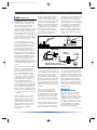
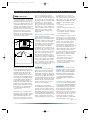
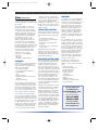
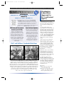
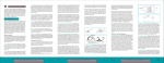
T&E Update/Issue16 1/31/02 12:31 PM Page 1
W
A
S
H
I
N
G
T&E
T
O
N
L
A
B
O
R
A
T
O
R
I
E
S ,
L
T
D
Update
Testing • Engineering • Consulting
Issue 16
Tools of the Trade:
Safety Design for Harmonized Compliance
INTRODUCTION
There are literally thousands of safety
standards in use around the world. The
good news is that harmonization allows
the manufacturer to design a single
product that complies with the requirements of numerous markets. The intent
of this “Tools of the Trade” installment
is to provide criteria that will assist
designers working with the more
common products on the market:
Computers, Medical Devices,
Machinery, Household Appliances and
Home Entertainment Equipment. While
this guide provides general and sometimes more detailed information, the
reader is advised to refer to the standard
that is applicable to his/her product for
specific requirements.
sidered hazardous. Currents that may
cause harm are in the 10’s of microamps
to 10’s of milliamps and the particular
standard provides the limits. The
frequency of the waveform of interest
is also important; lower frequencies are
more dangerous because they tend to
travel deeper through human tissue
and are more likely to affect the heart.
Higher frequencies present greater
danger of burns.
Mechanical: Moving parts - required
for correct function of the equipment
or ancillary to it (fans, etc.) - present a
physical hazard to the user of the
equipment. Guarding, interlocking or
other means should be provided to
minimize the risks. Also, the likelihood
that a product will tip over during use
is considered during the evaluation.
WHAT ARE HAZARDS?
Many of us think of hazards as harmful
to people. Hazards to the environment,
animals and sometimes damage to the
work-in-process are also considered.
The following are generally considered
when evaluating the hazards associated
with equipment. Conditions of normal
use, service and single faults or abnormal operation are reviewed as well.
Heating: Excessive temperatures can
cause burns, start a fire or degrade
insulation within the equipment. The
standards generally provide temperature
limits for various internal and external
parts. Installation or mounting methods
are considered when evaluating the
product: under-counter, installed in a
cabinet, etc.
Energy: The common PC power supply
is very happy sourcing 25 amps or more
at 5V. Even though the voltage will not
hurt anyone, there is enough current
available to melt insulation or start a
fire under certain conditions. Current
limiting is provided to reduce the risk of
this hazard.
Radiation: Lasers, RF emissions, audible
noise, X-rays and other radiation
sources are all potential hazards. The
equipment design must reduce the risk
of human exposure to these sources.
Shock: This is the most widely-recognized hazard. Studies have been done to
determine the voltages and currents
which are hazardous to people. As a
rule, voltages exceeding approximately
30Vrms, 42.2Vpeak or 60Vdc are con-
Other Hazards: There is a tremendous
variety of products on the market, each
with unique characteristics and potential
hazards. The applicable standards will
usually address the hazards associated
with the particular product or the risks
will usually be recognized and addressed
by product safety specialists.
GETTING POWER TO THE UNIT
Plugging In There are essentially three
ways to get power to your product:
Permanent wiring, fixed cord, and
appliance inlet or plug/socket. There are
specific requirements for each of these.
(1) For permanent wiring (often found
in industrial machinery), terminals are
usually provided within the equipment.
The terminals should be located close
together and should be sized to carry
the rated and anticipated fault currents
for the particular product. Installation
is often performed by an authorized
individual in accordance with the
electrical codes in force at the site.
(2) Fixed cords (non-detachable) are
often used in appliances. There may be
several different options allowed by
the standard, depending upon the
complexity of cord replacement.
These options may range from user
replaceable to non-replaceable (that is,
throw the device away if the cord is
damaged). Requirements for fixed cords
may include the type(s) of strain relief
allowed, the type of cord and wire
gauge required for a particular application and/or the maximum length of the
cord.
(3) Appliance inlets or plugs/sockets
provide distinct advantages over fixed
cords: appliance inlets are available with
integral fuse-holders and means for voltage selection, and they can have built-in
EMC filters. Inlets and plugs/ sockets
allow easy changeover to cord-sets for
different countries. Any inlets, plugs and
sockets must bear approvals for the
countries of intended use and must be
rated for the particular application.
continued on page 2
page 1
T&E Update/Issue16 1/31/02 12:31 PM Page 2
W
Tools
A
S
H
I
N
G
T
continued from page 1
Sizing the Wires: Phase Connections
Terminals and/or connections for Line
and Neutral must be adequately sized
(often dictated by the standard) and
must provide adequate protection
against loosening. Methods for providing such protection - often referred to as
‘double-securement’ - include: doublecrimp terminals, shrink-sleeving, cableties, lock washers, looping and hooking
soldered connections, etc. The goal is to
prevent a loose conductor from shorting
against other parts or circuits.
Protective Earthing (grounding for
electrical safety) Earthing or bonding
(often abbreviated PE-for “Protective
Earth”) offers a level of protection by
providing a path for fault currents
which - by design - will blow a fuse or
trip a circuit breaker. Some equipment
may include a Residual Current Device
(RCD), for Europe, or a Ground Fault
Circuit Interrupter (GFCI) for the US.
These devices detect fault currents and
open the circuit as a fuse or circuit
breaker would do. These are often used
in damp areas and in medical devices
where small, but lethal, leakage currents
can flow.
There are many requirements for PE. A
primary requirement is that doublesecurement be used. The protection of
PE connections must be taken care of at
the terminations themselves. That is, a
cable-tie or sleeving is not an option.
Double-crimp terminals, lock-washers
or hooking wires prior to soldering
must be used. There are ‘fast-on’ connectors available which meet the
requirements; these connectors provide
a double-crimp which secures the insulation and conductor independently and
have a ‘positive locking’ mechanism
which prevents the terminal from sliding
off by means of a tab and mating hole.
A tool may be required to remove such
a connector.
PE must “make first” and “break last”
when provided in a connector, for
example, where an auxiliary outlet is
available to plug in an accessory.
Approved plugs and sockets will meet
this requirement and many connector
manufacturers now provide pins of
different lengths to satisfy this
requirement.
O
N
L
A
B
O
R
A
T
The current path must be robust. PE
conductors and connections must
provide a low-impedance path from all
conductive surfaces to the supply earth.
Bare metal-to-metal mating surfaces
should be provided; this may mean that
surfaces may need to be masked prior
to painting. Also, attention should be
given to the types of metals being
used: dissimilar metals are subject to
corrosion due to “galvanic action” or
differences in electro-potentials.
O
R
I
E
S ,
L
T
D
requirements. A question that often arises is “What is the ratio of green to yellow?” Some, but not all, standards
answer this: 30% of one color and 70%
of the other. Further, it is recommended
(and specified in some standards) that
green OR yellow is not used ‘where
there is a possibility of confusion’ (no,
this does not apply to multi-conductor
signal or other cables-the intent is to
reduce confusion with the AC supply
wiring).
SMOKE¤
SOLDER¤
LUG
GROUND WIRE¤
CHASSIS
EMI FILTER
CHASSIS
CONNECTION
TO OTHER
GROUNDS
MECHANICALLY SECURED
GROUND: GREEN/YELLOW WIRE
SAME GAUGE AS OR BIGGER THAN SUPPLY
Terminal Markings Mark the terminals
for the supply connections with “L” and
“N,” for single-phase systems and with
“L1, L2, L3” (for the US) or with “U,
V, W” (for Europe) in three-phase
equipment. PE is generally identified by
the symbol • and/or by the letters ‘PE.’
Other terminals should be identified in
the product and should correlate with
the documentation for use and service.
Alpha-numeric designations are usually
acceptable.
Some standards recommend specific colors for wires in other circuits, but there
are few actual requirements beside the
above. Do note that the customer may
demand wire color standards to provide
consistency for service personnel or for
other site standards. The machinery
standard mandates that all wires must
be marked or identified in the product
and the service documentation. Other
agencies require replaceable cables to be
identified, as well.
Wire Colors and Markings In the
United States, black and white are
generally used to identify Line and
Neutral (respectively). Brown and blue
are the preferred colors in Europe for
Line and Neutral (respectively). Wire
colors will be correct in a cord which
bears approvals for the intended market.
ISOLATION FOR
ELECTRICAL PROTECTION
Protective Earth is usually green (US) or
green/yellow (International) however,
green/yellow can generally be used so
that one model will meet most market
Separation of Circuits One of the
fundamental means of preventing
hazards is to minimize the possibility
of hazardous circuits coming in contact
with other parts or circuits which, in
turn, may be accessible to the user of
the equipment. The means may consist
of Creepage Distance (i.e., distance
between two parts over a surface) or
Clearance (distance through air).
continued on page 3
page 2
T&E Update/Issue16 1/31/02 12:31 PM Page 3
W
Tools
A
S
H
I
N
G
T
continued from page 2
Creepage and Clearance are also known
as spacings. Spacings are measured by
the shortest distance between bare conductive parts. Mounting hardware used
to install PC boards (metal screws and
standoffs) can reduce the spacings below
acceptable values. Insulation may be
used, either alone or in conjunction with
spacings to provide the separation
between circuits. The standard will
identify the ways in which the separation may be provided as well as specific
requirements for each method.
Working Voltage One of the considerations for determining spacing requirements is Working Voltage. That is, the
maximum voltage that the relevant
insulation will be subjected to. The
voltage is measured between any two
points in the circuit (including voltages
to ground). It is recommended that the
derived Working Voltage should never
be less than the supply voltage in a
primary circuit regardless of the circuit
configuration or the measured values.
Further, periodic spikes that exceed the
nominal value (e.g., switching spikes)
are considered, but transient overvoltages are not.
Installation Category Another factor
that may be used to determine spacings
is Installation Category. Where is the
product installed in relation to the
power source? Is it before or after the
branch circuit protection? Is it connect-
O
N
L
A
B
O
R
A
T
ed to a low-voltage power supply?
There are four Installation Categories
that cover most products. Of these four,
the vast majority of products fall under
two: Category II is for equipment that is
powered by 100 - 240V~ after the
branch circuit protection and Category
III covers low-voltage products such as
keyboards, mice, etc. For example, in a
notebook computer with a brick power
supply, the power supply would be
Category II, and the computer itself
Category III.
Pollution Degree Yet another consideration for determining spacings is
Pollution Degree. This addresses where
the product is to be used and what environmental conditions it will be subjected
to. Circuits, components or products
that are likely to be exposed to moisture
or particulates in the air will require
larger spacings than items that are
encapsulated, used in a clean-room, etc.
For example, take a look at the ventilation slots on a desk-top computer power
supply; they’re likely to have ‘dust bunnies’ stuck to them. The build-up of
dust and other solid matter is likely to
cover the power supply board as well
and may become moist on a humid day.
Proper creepage distances are intended
to reduce the possibility that a conductive track and short-circuit could occur.
Proper clearances help assure that arcing
between live parts will not occur.
O
R
I
E
S ,
L
T
D
Guarding Barriers or covers over
hazardous parts can be used to reduce
risk. Such guards can prevent access to
high voltages, energy levels and mechanical hazards. The standards generally
identify the requirements for guards,
such as:
• a tool must be required to remove
the guard
• sizes of openings do not allow access
and
• the guard must be attached in some
way so that it can not be completely
removed and misplaced
Interlocks Interlocks operate to remove
hazards prior to access. Interlocks disable electrical sources and/or mechanical
hazards. Means for interlocking must be
reliable - often, the switch or device
must be cycle-tested. The interlock
should consist of electro-mechanical
components only and should not rely on
logic circuits or semiconductors. An
analysis should show that a single fault
can not render the interlock circuit
inoperable. Should it fail, it must fail in
the safe mode (i.e., hazard locked-out).
Other general considerations include:
• all hazards must be removed
before the cover can be opened
• the interlock switch cannot be
defeated by hand or without a tool
• the door or cover cannot be closed
with the switch defeated
ENCLOSURES
PROTECTION
It is important to protect people, animals and the environment from harm.
Electric shock, energy, fire, radiation
and mechanical hazards are among the
issues that are considered in setting safety design criteria. While the protection
provided should not impair the function
of the equipment, adequate safeguards
should be in place to meet these safety
objectives. Protection may consist of
some or all of the following:
Fusing Fuse protection will help
prevent hazardous voltages from being
accessible to the user (during a fault) or
large currents being drawn by the equipment. Fusing and circuit protection are
determined during the design phase as
well as during fault testing where shorts
and/or overloads will be imposed to
ensure that hazards can not be created.
Enclosures serve to prevent access to
hazards as well as to contain fire. The
standards outline a variety of requirements; for example, UL1950/EN60950
(Information Technology Equipment)
specifies limits for sizes and location
of openings plus the flammability
ratings and thickness requirements for
materials.
Mechanical Strength Enclosures intended to prevent access to hazards must be
strong enough to withstand anticipated
environmental conditions. Hand-held
products should not break open when
dropped and other equipment should
not create hazards if tipped over.
Further, the enclosure must not bend or
bow and reduce spacings or cause shortcircuits. Various tests are employed to
evaluate the strength of enclosures,
among them: steady forces and impacts
are applied and drop tests are percontinued on page 4
page 3
T&E Update/Issue16 1/31/02 12:31 PM Page 4
W
A
Tools
S
H
I
N
G
T
continued from page 3
formed. Following such tests, the product must remain safe in accordance with
the standard.
Flammability Plastic or other nonmetallic parts must not present a fire
hazard. Most often, UL 94 ratings are
acceptable for determining compliance
with this requirement. Generally, parts
with enough material to support and
sustain a fire must not be flammable.
PC boards may also have to be
adequately rated; many boards are
“94V-0” which meet most, if not all
requirements. The required ratings are
based on size, weight or mounting of
the equipment along with quantities and
locations of materials present. Be aware
that the flammability rating is often
based on material thickness and an
enclosure may not meet the requirements because it is too thin.
UL 94V-0 Least flammable
UL 94V-1
UL 94V-2
UL 94HB Most flammable
COMPONENTS
“Safety-related” components must meet
their relevant standards and must be
used in accordance with their ratings.
Such components include:
•
•
•
•
•
•
fuses and fuse-holders
power supplies and transformers
circuit breakers
relays
supply connectors
switches (in hazardous circuits) and
terminals
• wiring and terminals
The component vendor will usually provide the information needed to use the
part correctly. These parts will be identified and evaluated during the certification process, and changes that involve
these critical components must be evaluated to ensure continued compliance.
Buy Pre-Approved Parts It is always
better to procure parts that already bear
the required approvals. The components
should meet the requirements in force in
the intended market. That is, UL for the
US, IEC or EN for Europe, etc. It is
possible to use unapproved components
and, many times, evaluate them in the
end-product. Be aware, however, that
you are responsible for the continued
O
N
L
A
B
O
R
A
T
compliance of those parts and must
ensure that the component manufacturer does not make changes that affect
safety. Get the certificate from the
manufacturer– in the US it is a copy of
the UL “yellow card” and elsewhere it
would be a copy of an agency license or
similar certificate.
LABELING AND INSTRUCTIONS
The standards identify the information
that must appear on the product and/or
in the manuals. General requirements
are:
•
•
•
•
the manufacturer’s name or
rated voltage registered trademark
current or power
model number requirement and
frequency
• serial number or date code must be
on the product
Additionally, inputs and outputs,
indicators and controls, and operator
replaceable fuses should be marked.
All markings should be identified and
described in the manuals.
INSTALLATION, USER AND SERVICE
Instructions should be provided in manuals. The Installation Manual should
include all information necessary to
install the equipment. Examples are:
supply connections (power, air, water,
etc.), disconnect switches, over-current
protection, ventilation requirements and
other information appropriate for the
particular equipment. The User Manual
should contain all warnings and cautions along with all information for
proper operation, cleaning, etc. The
User Instructions MUST NOT direct the
user to expose him/herself to hazards
even when replenishing consumables or
making adjustments.
Language of User Instructions, as well
as labeling, has always been a difficult
topic. Generally, they should be in a
language appropriate for the intended
market. User Instructions for some
product categories, such as household
goods, must always be translated while
others, like those for machinery, laboratory equipment or medical products
may remain in English. Service Instructions should include all information
required to maintain the equipment;
replacement parts should be identified
and any other special considerations
should be explained.
page 4
O
R
I
E
S ,
L
T
D
CONCLUSION
Presented here are merely fundamental
issues affecting a product’s compliance
with various safety standards. The reader is urged to procure the standard(s)
appropriate for his or her equipment.
Remember too that there may be more
than one applicable standard; quite
often, the primary standard will list a
number of others (for components or
other aspects of the equipment) and
declaring or certifying compliance with
the ‘base’ standard implies compliance
with all.
It is also feasible to create one product
model that meets the requirements for a
number of markets. Of course, labeling
and language will change, but the basic
construction of the equipment may not
have to - just apply the more stringent
requirements and look for ways to meet
the intent of all standards. Remember
that the standards generally tell you
what to do but not how to do it, so,
with a little effort, your design can be
deemed to comply with all standards
relevant to your product.
In addition to an evaluation of a
product’s physical characteristics, a
number of tests are performed, among
them:
Dielectric Strength
Humidity Preconditioning
Insulation Resistance
Enclosure Strength
Leakage Current
Sound Level
Ground Impedance
Heating
Faults/ Abnormals
And others, as specified in the
relevant standard
You can reach us at:
WASHINGTON
LABORATORIES, LTD.
7560 Lindbergh Drive
Gaithersburg, MD 20879
301- 417-0220
800-839-1649
Fax: 301-417-9069
e-mail: [email protected]
web: www.wll.com
T&E Update/Issue16 1/31/02 12:31 PM Page 5
W
A
S
H
I
N
G
T
O
N
L
A
B
O
R
A
T
O
R
GAITHERSBURG LAB
MAY 17 AUGUST 16 NOVEMBER 8
FREDERICK LAB
MARCH 15 JUNE 7 OCTOBER 18
Norman Violette
will be the featured
speaker at our
Feb. 15 workshop
with his popular
discussion on
"The Principles of
Design for EMC.
Washington Labs has announced its Free Workshop
Schedule for 2002.These popular seminar/practical
workshops will include demonstrations, guest speakers,
the latest EMC and Safety compliance news, and lunch!
Each workshop will have a specific theme and guest
speaker! Be sure to register early as positions fill up quickly.
Call Patty or Ann at 800-839-1649 to register today.
EMC Testing and Measurements
Hands-On Safety Compliance
Designing to Avoid EMC
Problems Down the Road
Join us at our lab in Frederick for
hands-on practical workshops to
assist you with Product Safety
Compliance. You'll not only hear
and learn about the design tips
and information to help you with
new product design to ensure
safety– but you'll roll up your
sleeves and work with practical
demonstrations and test
simulations– all geared to
provide you with a 3-D picture
of designing for compliance.
Watch as our Gaithersburg Lab
engineers demonstrate several
testing techniques that uncover EMC
flaws in electrical and electronic
equipment– problems which can be
avoided before the testing stage.
You’ll have the opportunity to “get
specific” with the engineering staff
on particular problems you may
be encountering with current
R&D designs.
EMC and Military Standards Workshop
E
S ,
L
T
D
Washington
Laboratories
Approved As
UL Certificated
Agency
2002 Testing Workshop Series
FEBRUARY 15
I
Washington Laboratories recently
received notification from Underwriters’
Laboratories (UL) that the lab has been
approved under the UL Engineering
CAP.
As a UL Certificated Engineering
Agency, WLL can now perform UL testing without engineer-witnessing from a
UL representative. They are currently
approved for testing to UL60950 and
UL1950 and additional standards will
be added to the approval designation
over time. Previously UL had to witness
every test. This means WLL will have
greater freedom in scheduling their
clients and not be held to witnessing
timing.
“This is great news as it will greatly
improve our level of service to our
clients. No longer will we require UL in
order to schedule and begin testing of
products requiring compliance with
domestic safety standards. The process
will improve our turn-around time and
limit redundant testing,” said Mike
Violette, President of Washington
Laboratories.
WLL will be able to retest any failures
without UL having to return for a second visit; therefore, non-compliance
issues can also be resolved before any
data is forwarded to UL. Additionally,
UL and travel fees will decrease.
Since the inception of MIL-STD-461, the evolution of EMC technology has
rapidly increased. At the Washington Labs November workshop on EMC and
Military Standards, speakers included Steve Ferguson, Washington Labs VP of
Operations (left photo.) Steve led the discussion on MIL-STD-461E, which covers
the requirements for electronic equipment to be sold to the Department of Defense.
During the workshop practical session (right photo), attendees participated in test
technique demos on EMC design, methods for making radiated and conducted
meaurements, conducted and radiated susceptbility and EMP requirements.
For more information on our 2002 workshops see the article above or give
Patty or Ann a call to register at 800/839-1649.
page 5
Per WLL Safety Manager, Berri
Remenick, “WLL is now certified to
perform testing under the CAP program
at both the Gaithersburg and Frederick
lab facilities. The time-to-market for
our customers should greatly improve
because of this new certification and
streamlined process.”
The process:
● WLL sends project request and
proposed test plan to UL.
●
UL approves test plan and provides
cost limit. UL confirms if auditing
will be required for that project.
T&E Update/Issue16 1/31/02 12:31 PM Page 6
W
A
S
Approved
●
H
I
N
G
T
continued from page 5
WLL performs all testing, completes
UL report, sends test data and report
to UL along with sample for
construction review and auditing if
required.
● UL
reviews data and report, performs
audit testing if required. UL issues
approval.
Washington Laboratories is a full service
EMC and safety compliance testing
facility with offices in Gaithersburg and
Frederick, Maryland. For more
information on this new certification or
other services please call Berri Remenick
at 301/417-0220.
UNITED
WE STAND
O
N
L
A
B
O
R
A
T
O
R
I
E
S ,
L
T
D
Compliance Links
American Telecommunications
Certification Body, Inc (ATCB)
americantcb.com
The FCC has designated ATCB to issue
Equipment Authorizations under Part
2.960 of 47 CFR (FCC Rules and
Regulations). Prior to this program, the
only route for product certifications was
by submitting a formal application to
the FCC for Equipment Certifications
(including formerly-referred to applications called Type Acceptance). Under the
TCB program, ATCB, under its accreditation by American National Standards
Institute (ANSI), provides ISO Guide 65
Certification Services for electronic
products requiring FCC Certification.
National Technical Systems Corporation
ntscorp.com
(NTS) provides an extensive variety of
integrated services, including testing,
managed personnel and standards compliance. Washington Laboratories and
NTS have signed agreements to work
together in the area of Bellcore Testing
and related NRTL approvals.
Safety Link
safetylink.com
Website dedicated to Worldwide
Regulatory Compliance.
Syvax Design
syvaxdesign.com
Electronic product and systems developers specializing in state-of-the-art digital
design.
Technology International, Inc.
techintl.com
Competent and Notified Body for the
European Union.
Equipment Reliability Institute
equipment-reliability.com
Specialized technical training aimed at
increasing the reliability of equipment.
Example: Vibration and Shock Training.
Regulatory Compliance Information Center
rcic.com
RCIC is designated to provide the
updated compliance information to the
compliance industry.
The Reliability Center, Inc.
reliability.com
Reliability Consulting Services, Training
Programs and Software Tools for
Business, Government & Industry.
The Northeast Product Safety
Society, Inc. nepss.org
Technical Presentations on EMC
Immunity, Principles of IEC61010-1,
North American Telecom Standards,
Hazard Analysis, Demonstrations in
Inductance, International Product Safety,
Conformity in China, Product Safety
Labeling, GR-63/Central Office
Equipment, Restricted Substances, CE
Marking Process, Understanding
IEC60950, Hazardous Locations,
Telecom Regulatory Update,
International Approvals, Machinery
Directive, Laser Safety and lots more to
be announced..
Washington Laboratories, Ltd. Phone: 301- 417-0220 800-839-1649 Fax: 301-417-9069 e-mail: [email protected]
Washington Laboratories, Ltd.
7560 Lindbergh Drive
Gaithersburg, MD 20879
web: www.wll.com
Presort Standard
U.S. Postage
PAID
Permit No. 110
Frederick, MD
21701