1
Dolphin™ 70e Black
powered by Android 4.0
User’s Guide
Disclaimer
Honeywell International Inc. (“HII”) reserves the right to make changes in specifications and other
information contained in this document without prior notice, and the reader should in all cases consult HII
to determine whether any such changes have been made. The information in this publication does not
represent a commitment on the part of HII.
HII shall not be liable for technical or editorial errors or omissions contained herein; nor for incidental or
consequential damages resulting from the furnishing, performance, or use of this material. HII disclaims
any and all responsibility and liability for the selection and use of software and/or hardware to achieve
intended results.
This document contains proprietary information that is protected by copyright. All rights are reserved. No
part of this document may be photocopied, reproduced, or translated into another language without the
prior written consent of HII.
Web Address: www.honeywellaidc.com
Trademarks
Android, Google, Google Play and other marks are trademarks of Google Inc.
The Bluetooth trademarks are owned by Bluetooth SIG, Inc., U.S.A. and licensed to Honeywell.
Other product names mentioned in this manual may be trademarks or registered trademarks of their
respective companies and are the property of their respective owners.
Patents
For patent information, please refer to www.hsmpats.com.
2013-2014 Honeywell International Inc. All rights reserved.
Table of Contents
Chapter 1 - Dolphin 70e Black Terminal Agency Information
Label Locations ....................................................................................................................1-1
Model Number, Serial Number and IMEI Labels............................................................1-1
LED Safety ...........................................................................................................................1-1
LED Safety Statement....................................................................................................1-1
UL and C-UL Statement.......................................................................................................1-2
Approvals by Country...........................................................................................................1-2
R&TTE Compliance Statement—802.11a/b/g/n, Bluetooth, and/or GSM............................1-2
FCC Requirements ..............................................................................................................1-2
Dolphin RF Terminal—802.11a/b/g/n, Bluetooth, and/or GSM ......................................1-2
Canadian Compliance..........................................................................................................1-3
Conformité à la règlementation canadienne ..................................................................1-3
RF Exposure Information (SAR) ..........................................................................................1-4
Honeywell Scanning & Mobility Product Environmental Information....................................1-4
China RoHS .........................................................................................................................1-5
Pacemakers, Hearing Aids and Other Electrically Powered Devices ..................................1-5
Hearing Aid Compatibility (HAC)..........................................................................................1-5
Microwaves ..........................................................................................................................1-6
Informações ANATEL (Modelos: 70eLG0, e 70eL00) .........................................................1-6
Chapter 2 - Getting Started
Out of the Box ......................................................................................................................2-1
Memory Card Specifications ..........................................................................................2-1
Initial Setup for Dolphin 70e Black Terminal ........................................................................2-1
Identifying Your Model Type ..........................................................................................2-1
Installing the Battery in Terminals Equipped with a Battery Door Lock..........................2-2
Installing the Battery in Terminals without a Battery Door Lock.....................................2-3
Using the USB Charge/Communication Cable (Model 70e-USB ADAPTERKIT) ..........2-4
The Welcome Screen.....................................................................................................2-6
The Locked Screen ........................................................................................................2-6
The Home Screen ................................................................................................................2-7
Status Bar ......................................................................................................................2-7
Notification Panel ...........................................................................................................2-8
Common Status and Notification Icons ..........................................................................2-8
Search Bar ...................................................................................................................2-10
Personalize the Home Screen Panels and Favorites Tray ..........................................2-11
Apps and Widgets .......................................................................................................2-11
Navigation/Function Buttons ..............................................................................................2-11
Hotkeys ........................................................................................................................2-12
Virtual Keyboard ................................................................................................................2-12
The Enhanced Honeywell Virtual Keyboard.................................................................2-12
Honeywell Virtual Keypad Creator ..............................................................................2-13
Turning Power On/Off ........................................................................................................2-14
Suspend Mode ...................................................................................................................2-14
Airplane Mode ....................................................................................................................2-14
iii
Replacing the Battery ........................................................................................................ 2-15
Identifying Your Model Type ........................................................................................ 2-15
Replacing the Battery in Terminals Equipped with a Battery Door Lock ..................... 2-15
Replacing the Battery in Terminals Not Equipped with a Battery Door Lock............... 2-17
Resetting the Terminal ...................................................................................................... 2-18
Hard Reset (Cold Boot) ............................................................................................... 2-18
Connecting the Terminal to a Computer via a USB Connection ....................................... 2-19
\Honeywell ................................................................................................................... 2-20
AutoInstall Settings ...................................................................................................... 2-20
Additional Resources......................................................................................................... 2-20
Chapter 3 - Hardware Overview
Standard Configurations for the Dolphin 70e Black............................................................. 3-1
Peripherals for the Dolphin 70e Black ................................................................................. 3-2
Accessories for the Dolphin 70e Black ................................................................................ 3-3
Features of the Dolphin 70e Black ...................................................................................... 3-4
Front, Bottom, and Right Panels.................................................................................... 3-4
Feature Descriptions: Front, Bottom, and Right Panels ................................................ 3-5
Back, Top, and Left Panels............................................................................................ 3-7
Feature Descriptions: Back, Top, and Left Panels ........................................................ 3-9
The I/O Connector ............................................................................................................. 3-11
Battery ............................................................................................................................... 3-12
Replacement Battery Specifications ............................................................................ 3-12
Charging Options......................................................................................................... 3-13
Charging Time ............................................................................................................. 3-13
Important Charging Guidelines .................................................................................... 3-13
Managing Battery Power ............................................................................................. 3-15
Storing Batteries .......................................................................................................... 3-15
Guidelines for Battery Pack Use and Disposal ............................................................ 3-16
System Resets .................................................................................................................. 3-16
Hardware Maintenance ..................................................................................................... 3-16
Installing a SIM Card and/or Replacing the Memory Card ................................................ 3-17
Installation and/or Replacement .................................................................................. 3-17
Chapter 4 - Using the Scan Image Engine
Overview.............................................................................................................................. 4-1
LED Safety .......................................................................................................................... 4-1
Image Engine Specifications ............................................................................................... 4-1
Field of View .................................................................................................................. 4-1
Depth of Field ................................................................................................................ 4-1
Supported Bar Code Symbologies ..................................................................................... 4-2
Decoding ............................................................................................................................. 4-2
Using the Scan Demo to Decode a Bar Code ............................................................... 4-3
Configuring the Scan Demo Application ........................................................................ 4-4
Using the ScanTool Power Tool .................................................................................... 4-6
Aiming Beam ................................................................................................................. 4-6
iv
Capturing Images ................................................................................................................ 4-7
Taking an Image with the Imaging Demo ...................................................................... 4-7
Using the IQ Image Demo to decode intelligent bar codes and capture images........... 4-8
Configuring the IQ Image Demo Application ................................................................. 4-8
Using the Signature Demo............................................................................................. 4-9
Uploading Images........................................................................................................ 4-10
Chapter 5 - Using the Color Camera
Overview.............................................................................................................................. 5-1
Opening the Camera app and Adjusting the Settings ......................................................... 5-1
Adjusting the Camera/Video Settings ............................................................................ 5-1
Taking a Picture................................................................................................................... 5-2
Taking a Panoramic Picture........................................................................................... 5-2
Recording Video .................................................................................................................. 5-2
Uploading Pictures and Videos ........................................................................................... 5-3
Chapter 6 - Settings
Overview.............................................................................................................................. 6-1
Wireless & Network Settings ............................................................................................... 6-1
Device Settings.................................................................................................................... 6-1
Sound Settings .............................................................................................................. 6-1
Display Settings ............................................................................................................. 6-2
Honeywell Smart Sensors Settings ............................................................................... 6-2
Storage Settings ............................................................................................................ 6-3
Battery Settings ............................................................................................................. 6-3
Apps Settings................................................................................................................. 6-3
Managing Apps.............................................................................................................. 6-3
Personal Settings ................................................................................................................ 6-4
Accounts & sync ............................................................................................................ 6-4
Location Services .......................................................................................................... 6-5
Security.......................................................................................................................... 6-5
Encryption...................................................................................................................... 6-6
Language & input ................................................................................................................ 6-7
Backup & reset .................................................................................................................... 6-9
System................................................................................................................................. 6-9
Date & Time................................................................................................................... 6-9
Accessibility ................................................................................................................... 6-9
Developer options........................................................................................................ 6-10
About Phone...................................................................................................................... 6-10
Chapter 7 - Communication
Wireless & Networks Settings ............................................................................................. 7-1
Connecting the Terminal to a Wireless Network ................................................................. 7-1
v
Wi-Fi Network Connections ................................................................................................. 7-2
Turning Wi-Fi Networking On or Off .............................................................................. 7-2
Connecting to a Wi-Fi Network ...................................................................................... 7-2
Receiving Network Notifications .................................................................................... 7-2
Adding a Wi-Fi Network ................................................................................................. 7-2
Advanced Wi-Fi Settings and Network Utilities ................................................................... 7-3
Advanced Wi-Fi Menu ................................................................................................... 7-3
Wi-Fi Radio Settings Power Tool................................................................................... 7-3
Wireless Manager Power Tool....................................................................................... 7-4
Airplane Mode ..................................................................................................................... 7-4
Virtual Private Networks (VPN) ........................................................................................... 7-4
Adding a VPN ................................................................................................................ 7-4
Connecting to a VPN ..................................................................................................... 7-5
Disconnecting from a VPN............................................................................................. 7-5
Mobile Networks ............................................................................................................ 7-5
Ethernet Communication ..................................................................................................... 7-5
Chapter 8 - Working with Wireless Wide Area Networking (WWAN)
Overview.............................................................................................................................. 8-1
Requirements ................................................................................................................ 8-1
Antenna Band ................................................................................................................ 8-1
Signal Strength .............................................................................................................. 8-2
Voice and Data Communication .................................................................................... 8-2
Audio Modes.................................................................................................................. 8-2
Volume Control .............................................................................................................. 8-3
Using the Dolphin Terminal as a Phone .............................................................................. 8-3
Using the Phone App to Initiate a Call................................................................................. 8-3
Phone ............................................................................................................................ 8-3
Call Log.......................................................................................................................... 8-4
Contacts......................................................................................................................... 8-4
Answering or Diverting a Phone Call................................................................................... 8-4
Additional Options Available During a Call .................................................................... 8-5
Accessing Voicemail...................................................................................................... 8-5
Speed Dialing ................................................................................................................ 8-5
Phone App Settings............................................................................................................. 8-6
Fixed Dialing Numbers (FDN)........................................................................................ 8-6
Quick responses ............................................................................................................ 8-6
Voicemail ....................................................................................................................... 8-6
Audio Settings................................................................................................................ 8-6
Other Call Settings......................................................................................................... 8-6
Internet Call Settings ..................................................................................................... 8-6
Using the Voice Dialer App.................................................................................................. 8-8
Using the People App.......................................................................................................... 8-8
Using the Dolphin terminal for Data Communication via a Mobile Network ........................ 8-9
Mobile Network Settings ................................................................................................ 8-9
Adding or Editing an Access Point Name (APN) ......................................................... 8-10
Monitoring Data Usage ................................................................................................ 8-11
vi
Chapter 9 - Working with Bluetooth and NFC Technology
Bluetooth Technology.......................................................................................................... 9-1
Turning the Bluetooth Radio On or Off .......................................................................... 9-1
Pairing and Trusted Devices.......................................................................................... 9-1
Connecting to Other Bluetooth Devices......................................................................... 9-1
Configuring or Unpairing Bluetooth Devices.................................................................. 9-1
Making the Terminal Discoverable ................................................................................ 9-2
Bluetooth Menu Options ................................................................................................ 9-2
Sharing Pictures and Video ........................................................................................... 9-2
Near Field Communication (NFC) Technology.................................................................... 9-3
NFC Settings ................................................................................................................. 9-4
Reading NFC Tags ........................................................................................................ 9-4
Transferring screen content via NFC............................................................................. 9-5
Using the NFC Demos................................................................................................... 9-5
Chapter 10 - Working with GPS
Overview............................................................................................................................ 10-1
GPS and AGPS Settings ................................................................................................... 10-1
Using the GPS Demo ........................................................................................................ 10-1
Using the Logger in the GPS Demo ............................................................................ 10-2
Chapter 11 - Dolphin 70e Black HomeBase (Model 70e-HB)
Overview............................................................................................................................ 11-1
Unpacking the HomeBase ........................................................................................... 11-1
Charging Overview ...................................................................................................... 11-1
Communications .......................................................................................................... 11-2
Convenient Storage ..................................................................................................... 11-2
Capacity....................................................................................................................... 11-2
Dimensions .................................................................................................................. 11-2
Weight.......................................................................................................................... 11-2
Parts and Functions........................................................................................................... 11-3
Front Panel ................................................................................................................. 11-3
Back Panel .................................................................................................................. 11-4
Bottom Panel ............................................................................................................... 11-5
Power ................................................................................................................................ 11-5
Connecting Power to the HomeBase........................................................................... 11-5
Charging the Main Battery................................................................................................. 11-6
To Power a Terminal and Charge its Main Battery...................................................... 11-6
Charging a Spare Battery in the Auxiliary Battery Well ............................................... 11-6
Communication.................................................................................................................. 11-7
Requirements .............................................................................................................. 11-7
Setting Up and Connecting the Dolphin Terminal to the HomeBase........................... 11-7
Mounting the HomeBase ................................................................................................... 11-7
Optional DIN Rail Mount .............................................................................................. 11-7
vii
Chapter 12 - Dolphin 70e Black eBase (Model 70e-EHB)
Overview............................................................................................................................ 12-1
Unpacking the eBase................................................................................................... 12-1
Dimensions .................................................................................................................. 12-2
Weight.......................................................................................................................... 12-2
Parts and Functions........................................................................................................... 12-3
Front Panel .................................................................................................................. 12-3
Back Panel .................................................................................................................. 12-4
Bottom Panel ............................................................................................................... 12-5
Power ................................................................................................................................ 12-5
Connecting Power to the eBase .................................................................................. 12-5
Charging the Main Battery................................................................................................. 12-6
To Power a Terminal and Charge its Main Battery...................................................... 12-6
Charging a Spare Battery in the Auxiliary Battery Well ............................................... 12-6
Communication.................................................................................................................. 12-7
Establishing Ethernet Communication......................................................................... 12-7
Establishing USB Communication ............................................................................... 12-8
Mounting the eBase........................................................................................................... 12-8
Optional DIN Rail Mount .............................................................................................. 12-9
Chapter 13 - Dolphin 70e Black Mobile Base (Model 70e-MB)
Overview............................................................................................................................ 13-1
Charging Overview ...................................................................................................... 13-1
Convenient Storage ..................................................................................................... 13-1
Dimensions .................................................................................................................. 13-2
Weight.......................................................................................................................... 13-2
Mobile Base Components ................................................................................................ 13-2
Mounting the Mobile Base ................................................................................................. 13-3
Safety Precautions....................................................................................................... 13-3
Installation.................................................................................................................... 13-4
Charging the Main Battery................................................................................................. 13-5
To Power a Terminal and Charge its Main Battery...................................................... 13-5
Removing the Cable .................................................................................................... 13-6
Chapter 14 - Dolphin 70e Black ChargeBase (Model 70e-CB)
Overview............................................................................................................................ 14-1
Unpacking the ChargeBase......................................................................................... 14-1
Charging Overview ...................................................................................................... 14-1
Convenient Storage ..................................................................................................... 14-1
Capacity....................................................................................................................... 14-2
Dimensions .................................................................................................................. 14-2
Weight.......................................................................................................................... 14-2
Parts and Functions........................................................................................................... 14-3
Front Panel .................................................................................................................. 14-3
Back Panel................................................................................................................... 14-3
Bottom Panel ............................................................................................................... 14-4
viii
Power ................................................................................................................................ 14-4
Connecting Power to the ChargeBase ....................................................................... 14-4
Charging the Main Battery................................................................................................. 14-5
To Power a Terminal and Charge its Main Battery...................................................... 14-5
Mounting the ChargeBase................................................................................................. 14-5
Chapter 15 - Dolphin 70e Black Net Base (Model 70e-NB)
Overview............................................................................................................................ 15-1
Dimensions .................................................................................................................. 15-2
Weight.......................................................................................................................... 15-2
Parts and Functions........................................................................................................... 15-3
Front Panel .................................................................................................................. 15-3
Back Panel .................................................................................................................. 15-4
Bottom Panel ............................................................................................................... 15-5
Power ................................................................................................................................ 15-5
Connecting Power to the Net Base.............................................................................. 15-5
Charging the Main Battery................................................................................................. 15-5
To Power a Terminal and Charge the Main Battery .................................................... 15-6
Communication.................................................................................................................. 15-6
Establishing Ethernet Communication......................................................................... 15-6
Mounting the Net Base ...................................................................................................... 15-7
Chapter 16 - Customer Support
Product Service and Repair............................................................................................... 16-1
Technical Assistance......................................................................................................... 16-1
Warranty Disclaimer: Proper Use of a Touch Screen Mobile Device ................................ 16-1
Limited Warranty ............................................................................................................... 16-1
How to Extend Your Warranty ..................................................................................... 16-3
ix
x
1
Dolphin 70e Black Terminal Agency Information
Dolphin 70e Black mobile computers meet or exceed the requirements of all applicable standards
organizations for safe operation. However, as with any electrical equipment, the best way to ensure safe
operation is to operate them according to the agency guidelines that follow. Read these guidelines
carefully before using your Dolphin terminal.
This documentation is relevant for the following Dolphin models: 70eL00, 70eLGN, 70eLG0, 70eLWN,
70eLW0 and 70eL0N.
!
CAUTION - Read the Guidelines for Battery Pack Use and Disposal on page 3-16 and all cautionary markings
on the battery, charging peripheral, or device using the battery before attempting to install, use, or charge the
battery. Risk of fire and burns if improperly handled. Do not open, crush, heat above 60°C (140°F), or
incinerate.
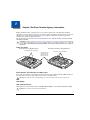
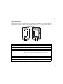
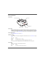
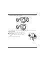
Label Locations
Model Type: IP67, Locking Battery Door
Model Type: IP54, Non-Locking Battery Door
Compliance Labels and Marks
Compliance Labels and Marks
Back Panel of the
terminal with the
battery door and
battery removed.
Model Number, Serial Number and IMEI Labels
The model (item) number, serial number, and international mobile equipment identity (IMEI) number for
the terminal are located on labels affixed to the bottom of the battery well.
Warning! To prevent possible hearing damage, do not listen at high volume levels for long periods.
LED Safety
LED Safety Statement
LEDs have been tested and classified as “EXEMPT RISK GROUP” to the Standard: IEC 62471:2006.
!
Caution! Do not view directly with optical instruments.
1-1
UL and C-UL Statement
UL and C-UL listed: UL60950-1 2nd Edition, and CSA C22.2 No. 60950-1-07 2nd Edition.
Underwriters Laboratories Inc. (UL) has not tested the performance or reliability of the global positioning
system (GPS) hardware, GPS operating software or other GPS-related aspects of this product. UL has
only tested for the explosion, fire, shock, and casualty hazards required by the applicable hazardous
locations standards. UL certification does not cover the performance or reliability of the GPS hardware,
GPS operating software, or other GPS-related aspects of this product. UL makes no representations,
warranties, or certifications whatsoever regarding the performance or reliability of any GPS-related
functions of this product.
Approvals by Country
Refer to the Honeywell Scanning & Mobility compliance center at www.honeywellaidc.com/compliance
to review and download any publicly available documentation pertaining to the certification of this
product in a given country.
R&TTE Compliance Statement—802.11a/b/g/n, Bluetooth, and/or GSM
The CE marking indicates compliance with the following directives:
• 1995/5/EC R&TTE
• 2011/65/EU RoHS (Recast)
In addition, this product complies to 2006/95/EC Low Voltage Directive when supplied with the recommended power supply. Honeywell shall not be liable for use of our product with equipment (i.e., power
supplies, personal computers, etc.) that is not CE marked and does not comply with the Low Voltage
Directive.
The equipment is intended for use throughout the European Community; PAN European Frequency
Range: 2.400–2.4835 GHz.
5Ghz band: UNII (Unlicensed National Information Infrastructure) or band1 (5.150 to 5.350 GHz) is
restricted to indoor use only. Any other use will make the operation of the device illegal.
High power radars are the primary users of 5250-5350 MHz and 5650-6850 MHZ bands. This may
cause interference to Wireless Local Area Network devices.
European Contact:
Hand Held Products Europe B.V.
Nijverheidsweg 9-13
5627 BT Eindhoven
The Netherlands
FCC Requirements
Dolphin RF Terminal—802.11a/b/g/n, Bluetooth, and/or GSM
This device complies with Part 15 of the FCC Rules. Operation is subject to the following two conditions:
(1) this device may not cause harmful interference, and (2) this device must accept any interference
received, including interference that may cause undesired operation.
1-2
This equipment has been tested and found to comply with the limits for a Class B digital device pursuant
to Part 15 of the FCC Rules. These limits are designed to provide reasonable protection against harmful
interference in a residential installation. This equipment generates, uses, and can radiate radio
frequency energy and, if not installed and used in accordance with the instructions, may cause harmful
interference to radio communications. However, there is no guarantee that interference will not occur in a
particular installation. If this equipment does cause harmful interference to radio or television reception,
which can be determined by turning the equipment off and on, the user is encouraged to try to correct
the interference by one or more of the following measures:
• Reorient or relocate the receiving antenna.
• Increase the separation between the equipment and receiver.
• Connect the equipment into an outlet on a circuit different from that to which the receiver is connected.
• Consult the dealer or an experienced radio/TV technician for help.
If necessary, the user should consult the dealer or an experienced radio/television technician for
additional suggestions. The user may find the following booklet helpful: “Something About Interference.”
This is available at FCC local regional offices. Our company is not responsible for any radio or television
interference caused by unauthorized modifications of this equipment or the substitution or attachment of
connecting cables and equipment other than those specified by our company. The correction is the
responsibility of the user. Use only shielded data cables with this system.
5Ghz band: UNII (Unlicensed National Information Infrastructure) or band1 (5.150 to 5.250 GHz) is
restricted to indoor use only. Any other use will make the operation of the device illegal.
Caution! - Any changes or modifications not expressly approved by the grantee of this device could void the user’s
authority to operate the equipment.
Canadian Compliance
This Class B digital apparatus complies with Canadian ICES-003. Operation is subject to the following
two conditions:
1.
This device may not cause harmful interference.
2.
This device must accept any interference received, including interference that may cause undesired
operation.
5Ghz band: UNII (Unlicensed National Information Infrastructure) or band1 (5.150 to 5.250 GHz) is
restricted to indoor use only. Any other use will make the operation of the device illegal.
For body worn operation, this phone has been tested and meets the FCC RF exposure guidelines for
use with the following body worn accessory: Holster-1. Use of other accessories may not ensure
compliance with FCC RF exposure guidelines.
Caution! - Any changes or modifications not expressly approved by the grantee of this device could void the user’s
authority to operate the equipment.
Conformité à la règlementation canadienne
Cet appareil numérique de la Classe B est conforme à la norme NMB-003 du Canada. Son
fonctionnement est assujetti aux conditions suivantes:
1.
Cet appareil ne doit pas causer de brouillage préjudiciable.
2.
Cet appareil doit pouvoir accepter tout brouillage reçu, y compris le brouillage pouvant causer un
fonctionnement indésirable.
1-3
Bande 5 Ghz: UNII (Infrastructure Nationale d'Information Sans Permis) ou Bande1 (5.150 à 5.250 GHz)
est limitée à l'usage intérieur seulement. Toute autre utilisation rendra l'opération de l'appareil illégal.
For body worn operation, ce téléphone a été testé et respecte les directives d'exposition RF de la FCC
pour une utilisation avec l'accessoire body worn: Holster-1. L'utilisation de d'autres accessoires risque
de ne pas assurer la conformité avec les directives d'exposition RF de la FCC.
Mise en garde! - Tout changement ou modification non expressément approuvées par le bénéficiaire de cet
appareil peut annuler l'autorisation d'utiliser l'équipement.
RF Exposure Information (SAR)
This mobile phone meets the government's requirements for exposure to radio waves. This phone is
designed and manufactured not to exceed the emission limits for exposure to radio frequency (RF)
energy set by the Federal Communications Commission of the U.S. Government.
The exposure standard for wireless mobile phones employs a unit of measurement known as the
Specific Absorption Rate, or SAR. The SAR limit set by the FCC is 1.6W/Kg and for Europe 2W/Kg.
Although the SAR is determined at the highest certified power level, the actual SAR level of the phone
while operating can be well below the maximum value. This is because the phone is designed to operate
at multiple power levels so as to use only the poser required to reach the network. In general, the closer
you are to a wireless base station antenna, the lower the power output.
The highest reported SAR values for head, body-worn accessory and simultaneous transmission use
conditions are: 0.45 W/kg (1g), 0.96 W/kg (1g) and 1.33 W/kg (1g).
The highest reported CE SAR values for head, body-worn accessory and simultaneous transmission
use conditions are: 0.59 W/kg (10g), 1.0 W/kg (10g), 1.15 W/kg (10g).
While there may be differences between the SAR levels of various phones and at various positions, they
all meet the government requirement.
The FCC has granted an Equipment Authorization for this model phone with all reported SAR levels
evaluated as in compliance with the FCC RF exposure guidelines. SAR information on this model phone
is on file with the FCC and can be found under the Display Grant section of www.fcc.gov/oet/ea/fccid
after searching on FCC ID: HD570eLGN, HD570eLG0 and HD570eL00.
For body worn operation, this phone has been tested and meets the FCC RF exposure guidelines for
use with the following body worn accessory: Holster-1. Use of other accessories may not ensure
compliance with FCC RF exposure guidelines.
Honeywell Scanning & Mobility Product Environmental Information
Refer to www.honeywellaidc.com/environmental for the RoHS / REACH / WEEE information.
1-4
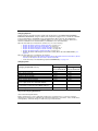
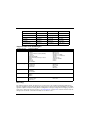
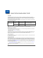
China RoHS
有毒有害物质名称及含量
部件名称 (Parts Name)
(Names and Content of Hazardous Substances or Elements)
有毒有害物质或元素 (Toxic and Hazardous Substances or Elements)
铅 (Pb)
汞 (Hg)
镉 (Cd)
六价铬 (Cr6+)
多溴联苯 (PBB)
多溴二苯醚 (PBDE)
成像式条码阅读器 (Imager)
o
o
o
o
o
o
印刷电路板 (PCB)
o
o
o
o
o
o
主机及基座外壳 (Housing)
o
o
o
o
o
o
连线 (Cables)
o
o
o
o
o
o
液晶显示器 (LCD)
o
o
o
o
o
o
液晶显示器框架 (LCD Frame)
o
o
o
o
o
o
相机模组 (Camera)
o
o
o
o
o
o
按键 (Key)
o
o
o
o
o
o
电池 (Battery)
o
o
o
o
o
o
电源供应器 (Power Adapter)
o
o
o
o
o
o
o: 表示该有毒有害物质在该部件所有均质材料中的含量均在SJ/T11363-2006标准规定的限量要求以下 (Indicates that this toxic or hazardous substance contained in all of the homogeneous
materials for this part is below the limit requirement in China’s SJ/T11363-2006.)
x: 表示该有毒有害物质至少在该部件的某一均质材料中的含量超出 SJ/T11363-2006 标准规定的限量要求 (Indicates that this toxic or hazardous substance contained in at least one of the
homogeneous materials for this part is above the limit requirement in China’s SJ/T11363-2006. )
Pacemakers, Hearing Aids and Other Electrically Powered Devices
Most manufacturers of medical devices adhere to the IEC 601-1-2 standard. This standard requires
devices to operate properly in an EM Field with a strength of 3V/m over a frequency range of 26 to
1000MHz. The maximum allowable field strength emitted by the Dolphin terminal is 0.3V/m according to
Subpart B of Part 1 of the FCC rules. Therefore, the RF from the Dolphin terminal has no effect on
medical devices that meet the IEC specification.
Hearing Aid Compatibility (HAC)
Dolphin 70e Black models 70eLGN and 70eLG0 have been tested for hearing aid compatibility. These
devices have an M4 and T4 rating. For additional HAC information, including the HAC rating for this
product, please refer to www.honeywellaidc.com.
When some wireless devices are used near some hearing devices such as hearing aids and implants,
users may detect a buzzing or humming noise. Some hearing devices are more immune than others to
this interference noise. Wireless devices may also vary in the amount of interference they generate.
The ratings for compatibility of digital wireless devices with hearing aids are described in the American
National Standards Institute (ANSI) C63.19 standard:
M-Rating: Phones rated M3 or M4 meet FCC requirements and are likely to generate less interference
with hearing devices than phones that are not labeled. M4 is the superior/higher of the two ratings.
T-Rating: Phones rated T3 or T4 meet FCC requirements and are likely to be more usable with hearing
devices' telecoil than unrated phones. T4 is the superior/higher of the two ratings.
The more immune the hearing aid device is, the less likely one is to experience interference noise from
the wireless phone. Hearing aid devices may also be rated. Adding the ratings of the hearing aid and the
phone would determine probable usability:
• Any combined rating equal to or greater than six offers the best use.
• Any combined rating equal to five is considered normal use.
1-5
The ratings are not guarantees. Results will vary depending on the user's hearing device and hearing
loss. If your hearing device happens to be vulnerable to interference, you may not be able to use this
device successfully. Trying out this device with your hearing device is the best way to evaluate it for your
personal needs.
This device has been tested and rated for use with hearing aids for some of the wireless technologies
that it utilizes. However, there may be some newer wireless technologies used in this phone that have
not been tested yet for use with hearing aids. It is important to try the different features of this phone
thoroughly and in different locations, using your hearing aid or cochlear implant, to determine if you hear
any interfering noise. Consult your service provider or the manufacturer of this phone for information on
hearing aid compatibility.
Microwaves
The radio in the Dolphin RF terminal operates on the same frequency band as a microwave oven.
Therefore, if you use a microwave within range of the Dolphin RF terminal you may notice performance
degradation in your wireless network. However, both your microwave and your wireless network will
continue to function.
Informações ANATEL (Modelos: 70eLG0, e 70eL00)
Medida de SAR (distância mínima com relação ao corpo do usuário):
quando com os acessórios: 0 cm, quando sem os acessórios: 1,5 cm.
Este produto está homologado pela Anatel, de acordo com os procedimentos regulamentados pela
Resolução No. 242/2000 e atende aos requisitos técnicos aplicados incluindo os limites de exposição
da Taxa de Absorção Específica referente a campos elétricos, magnéticos e eletromagnéticos de radiofreqüência, de acordo com a Resolução No. 303/2002 e nº 533/2009.
" Este equipamento opera em caráter secundário, isto é, não tem direito a proteção contra interferência
prejudicial, mesmo de estações do mesmo tipo, e não pode causar interferência a sistemas operando
em caráter primário."
Modelo: 70eLG0 (Dolphin 70e Black)
Modelo: 70eL00 (Dolphin 70e Black)
2941-13-6583
2935-13-6583
(01)07898927490270
(01)07898927490263
Para maiores informações, consulte o site da ANATEL - www.anatel.gov.br.
Compatibilidade entre carregadores, baterias e acessórios:
Os modelos 70eLG0 e 70eL00 (Dolphin 70e Black) serão fornecidos com baterias modelo 70e-BTEC,
n° de homologação 3936-13-0003 e modelo 70e-BTSC n° de homologação 3935-13-0003.
1-6
Os modelos 70eLG0 e 70eL00 (Dolphin 70e Black) serão fornecidos com os seguintes carregadores /
fontes de alimentação:
Carregador modelo FRA036-S12-4: número de homologação ANATEL 1615-12-8020.
Este carregador será comercializado com as seguintes bases/docas/periféricos: 70E-HB e
70E-EHB.
Carregador modelo DSA-5CU-05 050100: número de homologação ANATEL 2939-13-8022.
Os modelos 70eLG0 e 70eL00 (Dolphin 70e Black) serão comercializados com os seguintes modelos
de acessório: 70e-EHB, 70e-COVER.
1-7
1-8
2
Getting Started
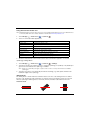
Out of the Box
Verify that the carton contains the following items:
• Dolphin 70e Black mobile computer (terminal)
• 1 GB, 2 GB or 4 GB microSD™ Memory Card (pre-installed)
• 3.7V Li-ion rechargeable battery
• USB charge/communication cable
• Power adapter with regional plug adapters
• Quick start guide
• Compliance Regulatory Sheet
If you ordered accessories for your terminals, verify that they are also included with the order. Be sure to
keep the original packaging in the event that the Dolphin terminal should need to be returned for service.
Memory Card Specifications
Applications on your Dolphin 70e Black terminal utilize the memory card to store files and application
data. A microSD memory card is included and pre-installed in the device. Memory card use is
recommended to avoid potential application errors or possible data loss.
Honeywell recommends the use of Single Level Cell (SLC) industrial grade microSD or microSDHC™
memory cards with Dolphin terminals for maximum performance and durability. Contact a Honeywell
sales representative for additional information on qualified memory card options.
Initial Setup for Dolphin 70e Black Terminal
Step 1. Install the Battery
Note: Before installing the main battery, read the Guidelines for Battery Pack Use and Disposal on page 3-16.
The terminal is shipped with the battery packaged separate from the unit. To install the battery, first
identify your model type, and then follow the installation steps on the pages indicated below.
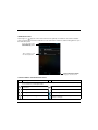
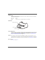
Identifying Your Model Type
Dolphin 70e Black model terminals equipped with a battery door lock are designed for use with
battery part numbers BAT-STANDARD-02 (Li-ion 3.7V, 6.179 watt hour) and BAT-EXTENDED-02
(Li-ion 3.7V, 12.358 watt hour) manufactured for Honeywell International Inc. See page 2-2 for battery
installation instructions.
Back panel of the terminal
with standard battery door
shown.
Battery Door Lock
2-1
Dolphin 70e Black model terminals not equipped with a battery door lock are designed for use with
battery part numbers BAT-STANDARD-01 (Li-ion 3.7V, 6.179 watt hour) and BAT-EXTENDED-01
(Li-ion 3.7V, 12.358 watt hour) manufactured for Honeywell International Inc. See page 2-3 for battery
installation instructions.
Back panel of the terminal
with standard battery door
shown.
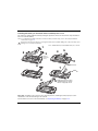
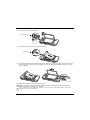
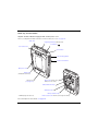
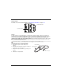
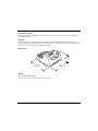
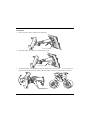
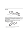
Installing the Battery in Terminals Equipped with a Battery Door Lock
The terminal is shipped with the battery packaged separate from the unit. Perform the steps illustrated
below to install the battery.
Note: If your Dolphin 70e Black model type does not have a battery door lock, refer to the battery installation
instructions on page 2-3.
!
Ensure all components are dry prior to placing the battery in the terminal. Mating wet components may cause
damage not covered by the warranty.
2
Battery Door Lock
Note: Standard battery and standard battery door shown.
1
4
5
6
3
Apply pressure to the edges
of the battery door before
engaging the lock to ensure
the door is properly closed.
Important - All battery and connector doors must be present, undamaged, and properly closed to
maintain the environmental rating of the terminal.
For information on how to remove the battery, see Replacing the Battery on page 2-15.
2-2
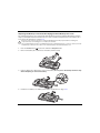
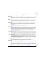
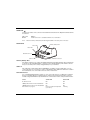
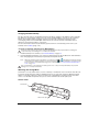
Installing the Battery in Terminals without a Battery Door Lock
The terminal is shipped with the battery packaged separate from the unit. Perform the steps illustrated
below to install the battery.
Note: If your Dolphin 70e Black model does not have a battery retention strap, refer to the battery installation
instructions on page 2-2.
!
Ensure all components are dry prior to placing the battery in the terminal. Mating wet components may cause
damage not covered by the warranty.
Note: Standard battery and standard battery door shown.
1
2
5
4
3
Battery
Retention
Strap
6
7
8
9
Apply pressure to the edges
of the battery door to ensure
the door is properly closed.
Important - All battery and connector doors must be present, undamaged, and properly closed to
maintain the environmental rating of the terminal.
For information on how to remove the battery, see Replacing the Battery on page 2-15.
2-3
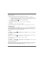
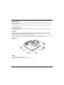
Step 2. Charge the Battery
The power source for the Dolphin terminal is the 3.7V Li-ion rechargeable battery located under the
battery door on the back panel of the device. See Battery on page 3-12 for additional information on
battery storage, use, and disposal.
Important: Removing the battery from the terminal erases all non-persistent memory. Always place the terminal in
Suspend mode before removing the battery. For information on how to remove the battery from the terminal, see
Replacing the Battery on page 2-15.
Before Initial Use
Dolphin terminals ship with the battery significantly discharged of power. After installing the battery in the
terminal, charge the battery with a Dolphin 70e Black charging peripheral for a minimum of 4 hours for
the standard battery pack or 6 hours for the extended battery pack. When using the 70e-USB Charge/
Communication cable to charge from a 500mA USB port on a host device, charge the battery for a
minimum of 6 hours for the standard battery and 8 hours for the extended battery.
Note: Inadequate source current may interfere with effective battery charging; see Important Charging
Guidelines on page 3-13 for additional information.
!
We recommend use of Honeywell peripherals, power cables, and power adapters. Use of any non-Honeywell
peripherals, cables, or power adapters may cause damage not covered by the warranty.
Dolphin 70e Black model terminals are designed for use with the following charging devices and cables:
70e-HB, 70e-CB, 70e-EHB, 70e-NB, 70e-MB, 70e-MC, and 70e-USB ADAPTERKIT. See pages 3-2 and
3-3 for additional information on Dolphin 70e Black peripherals and accessories.
!
Ensure all components are dry prior to mating terminals/batteries with peripheral devices. Mating wet
components may cause damage not covered by the warranty.
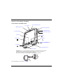
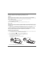
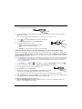
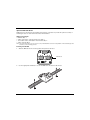
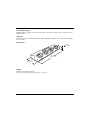
Using the USB Charge/Communication Cable (Model 70e-USB ADAPTERKIT)
Dolphin 70e Black terminals ship with a USB Charge/Communication Cable and a power adapter with
regional plug adapters. The USB Charge/Communication cable provides two options for charging the
terminal. Use the cable in conjunction with the provided power supply adapter and plug adapter to
charge the terminal from a power outlet (Option 1 on page 2-5) or connect the cable to a high-power
USB port to charge from a host device (Option 2 on page 2-5).
!
2-4
Warning - The terminal shall only be connected to CTIA certified adapters, products that bear the USB-IF logo
or products that have completed the USB-IF compliance program when using the micro USB port as a
charging source.
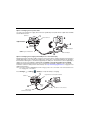
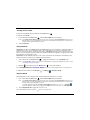
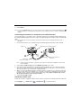
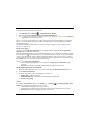
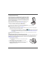
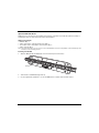
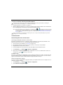
Option 1: Charging from a power outlet
Use only a UL Listed power supply, which has been qualified by Honeywell with an output rated at 5VDC
and 1A with the device.
USB Door
1
5
Micro USB Port
Right Side Panel of
Dolphin 70e Black
4
2
Plug Adapter
USB Charge/Communication
Cable
Power Adapter
3
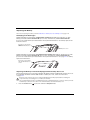
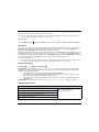
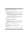
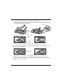
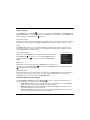
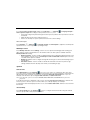
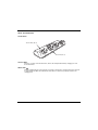
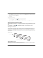
Option 2: Charging from a high power USB port on a host device (PC)
Charging the battery through a USB port takes more time than direct charging using the provided power
supply. Inadequate source current may lengthen the charge time or prevent the battery from charging if
the terminal is drawing more current than supplied by the USB port. The maximum current supplied by a
USB Host can vary from 100mA to 500mA. Do not attempt to charge the terminal from a 100mA
source. An active Dolphin terminal uses more current than supplied by a 100mA source causing the
terminal to continue to draw power from the battery. See Important Charging Guidelines on page 3-13 for
additional information.
Note: Placing the terminal in Suspend mode while charging reduces the current draw of the terminal and shortens
the charging time of the battery.
Touch All Apps
> Settings
USB Door
> Battery to verify the battery is charging.
1
Right Side Panel of Dolphin 70e Black
3
2
Micro
USB
Port
USB Port on Host Device
USB Charge/
Communication Cable
2-5
Step 3. Boot the Terminal and Access the Home Screen
The terminal begins the boot process as soon as power is applied. Do not press any buttons or attempt
to remove the battery during the initial boot process.
The Welcome Screen
The first time you power up the Dolphin terminal, a Welcome screen appears after the boot process is
finished. From the Welcome screen follow the prompts as the Setup Wizard guides you through:
•
•
•
•
•
•
•
setting the default language for the terminal,
setting up Wi-Fi network connections,
connecting to an existing Gmail™ account or creating a new Gmail account
setting the time, date, and time zone,
turning the Google Location Service™ on or off
personalizing (naming) the terminal, and
selecting your preference for automatic updates from Google™ and reviewing the Google
privacy policy.
After the initial Setup Wizard is complete the Locked Screen (see page 2-6) displays.
Note: Once you complete the initial Setup Wizard, the Welcome screen no longer appears when you reboot the
device. The Locked screen displays after the terminal completes the boot process.
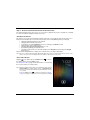
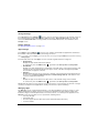
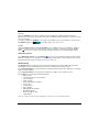
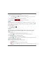
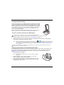
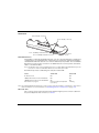
The Locked Screen
Drag the
to the right or press the Menu button
the display and access the Home screen.
to unlock
See Screen Security on page 6-5 for information on customizing
the screen lock/unlock security feature.
Note: During the initial charging stage, the terminal may have entered
Suspend Mode to conserve battery power. In Suspend mode
the touch screen dims then darkens automatically after a period
of no activity.
Press the Power button
to wake the terminal. See Display
Settings on page 6-2 to adjust the screen sleep (timeout) settings.
2-6
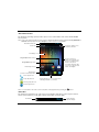
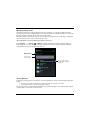
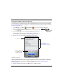
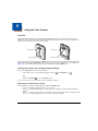
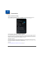
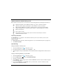
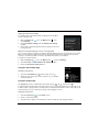
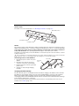
The Home Screen
The Android™ operating system provides space for user customization and control with five Home
Screen panels.
Note: Some of the features listed below are specific to Dolphin 70e Black models equipped with Google Mobile™
Services and may require an active Google account be setup on your terminal.
Notification/Status Bar
Touch
to initiate a voice
search or command.
Search Bar
Clock Widget
Google Play™ store Shortcut
Home Screen Panel
Swipe left or right with your
finger to scroll between five
Home screen panels.
Google Mobile App Folder
Personalize the panels with
your choice of app shortcuts,
folders, and widgets.
Camera App Shortcut
Favorites Tray
(Content is model dependent.)
Phone App Shortcut
People App Shortcut
Tap the All Apps icon
to view the apps
and widgets loaded on your device.
Messenger App Shortcut
Browser App Shortcut
Note: You can return to the Home screen at any time, in any application by pressing the
button.
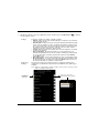
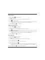
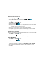
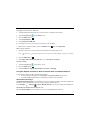
Status Bar
The status bar located at the top of the touch screen displays notifications (on the left), the status of
various system functions (on the right), and the current time (on the far right).
Notifications
Status Indicators
and Time Display
2-7
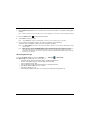
Notification Panel
A plus sign icon
appears on the status bar when the quantity of notifications exceed the available
space on the bar. To view all the notifications, touch and hold the status bar, and then drag down to open
the notification panel.
Touch and hold the status
bar, and then drag down to
view notifications.
Tap a notification to open
the related application.
Touch and hold the circle at the
bottom of the screen, and then
drag up to close the screen.
Common Status and Notification Icons
Icon
Meaning
Note: Status and notification icons are hardware and software dependent. Some of the icons listed below may
not be relevant for your Dolphin model.
2-8
Open notification panel to see additional
notifications
Sound is turned off
Pending calender event
Vibrate mode is turned on
Pending alarm and Alarm is set
Battery charge is at 100%.
New Hangouts™ message
Terminal is connected to external power and the
battery is charging.
Icon
Meaning
New Gmail™ message
SD card or USB storage is full
New text message or multimedia message
Bluetooth technology is turned on
New E-mail
Terminal connected to a device with Bluetooth
technology
Error with text or multimedia message
delivery
Bluetooth incoming file notification
Terminal is connected to a computer using a
USB cable
WWAN (voice & data) network signal strength
ABD active (USB debugging enabled)
The carrier data use threshold has been reached
or exceeded
Uploading data
Wi-Fi network connected and signal strength
Downloading data
Ethernet status - disconnected
Download finished
Ethernet status - connected
Synchronizing data
Music player active
Error with sync or sign-in
Call in progress
The terminal could not synchronize data with
the computer
Call in progress using a headset with Bluetooth
technology
GPS is turned on
Call forwarding turned on
Receiving location data from GPS
Call on hold
Missed call
No SIM card is installed
New Voicemail message
Speaker phone is on
Call is muted
2-9
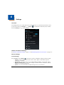
Search Bar
You can search for an item on the terminal or the Internet using Google™ Search at the top of any
Home screen panel.
Touch
to initiate Google Voice
Search or a Voice Action.
Touch inside the box to
access the virtual keyboard
for text entry.
To modify the search settings:
1.
Touch inside the box then press the Menu button
.
2.
Touch Settings then select Searchable items or Google Search.
Voice Search and Voice Actions
To initiate Google Voice™ Search or a Voice Action select the microphone on the search bar. Speak
the terms to search for or the Voice Action to perform. For example, say “What time is it in France” or
“send email”.
Touch Help to access Tutorials (e.g., video and sample Voice Action commands) or connect to the
Google Help Center.
Touch the wrench
2 - 10
to configure Voice Search settings (see page 6-8).
Personalize the Home Screen Panels and Favorites Tray
Streamline your work flow by customizing the Home screen panels and Favorites tray with your choice
of app shortcuts, folders, and widgets.
To add an app shortcut:
1.
Touch All Apps
.
2.
Select and hold the app icon you want to add. The terminal vibrates, and then switches to the home
screen.
3.
Drag and drop the icon into position on the Home screen or in an open spot on the Favorites tray.
Hints:
• To create a folder, drag and drop an app icon on top of another icon.
• To move a shortcut from the Favorites tray to the Home screen panel, touch and hold the item,
and then drag and drop the icon onto the Home screen.
To add a widget:
1.
Touch All Apps
.
2.
Select the Widget tab.
3.
Touch and hold the widget you want to add. The terminal vibrates and switches to the Home screen.
4.
Drag and drop the widget into the desired position.
To remove/delete an item:
1.
Touch and hold the item.
2.
Drag the item to the top of the screen where the word Remove is displayed.
To move an item:
1.
Tap and hold the item.
2.
When the unit vibrates, drag and drop the item in the new location.
Note: The next panel automatically opens if you drag the item to the edge of the touchscreen.
Apps and Widgets
Touch the All Apps icon
loaded on your terminal.
located at the bottom of any Home screen to see the all apps and widgets
Navigation/Function Buttons
The Dolphin terminal has seven navigation/function buttons.
Button
Function
Home
A quick press returns you to the Home screen.
Press and hold the button to view and switch between recently used apps.
2 - 11
Button
Function
Menu
Opens additional menu options.
Scan
Wakes the terminal from Suspend Mode.
Triggers the scanner/imager in the following apps: IQ Image Demo, Imaging Demo
and Scan Demo.
Triggers the scanner/imager when ScanWedge is enabled. Refer to the Dolphin
Power Tools User’s Guide available for download at www.honeywellaidc.com.
Back
Back to the previous screen.
Search
Initiate a search of the terminal or the Internet.
Right and
Left Side
Triggers the scanner/imager in the following apps: IQ Image Demo, Imaging Demo
and Scan Demo.
Triggers the scanner/imager when ScanWedge is enabled. Refer to the Dolphin
Power Tools User’s Guide available for download at www.honeywellaidc.com.
Volume
Raises or lowers the volume of the active speaker.
Hotkeys
You can configure the Scan button and the Left and Right side buttons of the terminal to launch specific
applications.
Touch All Apps
> Power Tools
> Configure Hotkeys
. Touch the box next to the key being
configured. Select the app you want assigned to the key from the associated menu.
Refer to Features of the Dolphin 70e Black on page 3-4 for button locations on the terminal.
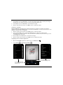
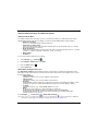
Virtual Keyboard
The enhanced Honeywell virtual keyboard appears when you open an application or select a field that
requires text or numerical input. The content of the keyboard may vary depending on the application in
use and the input field requirements. The enhanced Honeywell virtual keyboard is fully customizable
using the Honeywell Virtual Keypad Creator and is the selected as the default method for entering text.
See Language & input on page 6-7 for additional information on configuring keyboard & input methods.
The Enhanced Honeywell Virtual Keyboard
During text input, you may need to switch between keyboard modes to access additional character sets
(e.g., function keys, symbols, and numbers). Each keyboard mode, includes navigation keys, which allow
you to quickly switch between modes. Touch the ABC key to switch to the Qwerty Mode, the 123 key to
switch to the Numeric Mode, and the #@& key to switch to the Function & Symbols Mode.
Note: The content of the keyboard and the mode initially displayed may vary depending on the application in use
and the input field requirements.
2 - 12
Alternate Keys
Some keys include a second symbol in red. In order to use the alternate symbol, touch and hold the key
until the alternate symbol appears, and then release the key to type the symbol.
Honeywell Virtual Keypad Creator
The default enhanced Honeywell virtual keyboard is fully customizable using the Honeywell Virtual
Keypad Creator software available for download at www.honeywellaidc.com. The user-friendly utility
allows you to personalize multiple keyboard features including key position, size, quantity, color, and the
keyboard skin. In addition, you can make language changes, create alternate or function keys for special
character sets, and add application launch keys to streamline common business tasks.
There are two software components required for customizing the enhanced Honeywell Virtual keyboard.
• The first is the Honeywell Virtual Keypad Creator, which resides on your PC and is used to design,
save, and download custom keyboard layouts to your Dolphin terminal.
• The second is the enhanced Honeywell virtual keyboard file HoneywellVK.xml, which is located in the
\mnt\SDcard\HoneywellVK folder on your Dolphin terminal. This keyboard file is what displays on
the terminal screen when the enhanced Honeywell virtual keyboard is selected as the default virtual
keyboard; see Language & input on page 6-7.
The customization process is easy.
1.
Download and install the Honeywell Virtual Keypad Creator software onto your PC.
2.
Connect your Dolphin terminal your PC using the USB charge/communication cable provided.
3.
Configure the terminal for USB debugging and the installation of Unknown sources (non-Market
apps).
a. Touch All Apps
> Settings
> Developer Options. Check USB debugging.
b. Touch All Apps
> Settings
> Security. Check Unknown sources.
4.
Open the Virtual Keypad Creator software on your PC.
5.
Select Android from the Device menu, and then Yes to confirm changing the device platform.
6.
Open and modify the standard layout or create a new layout.
Note: Select Help > Contents or click the Help icon for detailed information on how to open, modify and
create new keypad layouts.
7.
Select File > Save As.
Note: The Save button overwrites the default keypad template provided with the software with any changes
you have made to the layout. Make a backup copy of the template or use the Save As option if you want
to keep the provided default template for later use.
8.
Select Device > Update Configuration. Follow the prompts to install the custom enhanced virtual
keyboard on your terminal.
2 - 13
Turning Power On/Off
To turn the terminal On, press and release the Power button
.
To turn the terminal Off:
1.
Press and hold the Power button
until the Phone Options menu displays.
Note: If the Show System Dialog setting is turned off (see page 6-2), the Phone Options menu does not
display when you press and hold the Power button. The terminal automatically reboots when Power
button is held for approximately 8 seconds.
2.
Touch Power Off.
Suspend Mode
Suspend mode differs from Power off mode. Power off mode is the equivalent to having no battery or
external power source connected to the device. The terminal does not receive incoming calls when
power is off since the device completely shuts down. In Suspend mode, the device enters a low power
state to conserve battery power. The radio associated with the phone maintains enough power to wake
the terminal for incoming phone calls.
Suspend mode automatically turns the touch screen off and locks the terminal to save battery power
when the terminal is inactive for a programmed period of time.
1.
Press and release the Power button
to toggle the terminal in or out of Suspend mode.
Note: If the Power key setting has been turned off (disabled), pressing and releasing the key has no effect.
See Display Settings on page 6-2.
2.
Drag the
to the right or press the Menu button
to unlock the terminal.
Note: You should always place the terminal in Suspend mode before removing the battery. For information on
removing the battery, see Replacing the Battery.
To adjust the timeout limit, touch All Apps
> Settings
> Display > Sleep.
Airplane Mode
Turn On Airplane mode to disable all the terminal radios that transmit voice or data.
1.
Press and hold the Power button
until the Phone Options menu displays.
Note: If the Show System Dialog setting is turned off (see page 6-2), the Phone Options menu does not
display when you press and hold the Power button. The terminal automatically reboots when Power
button is held for approximately 8 seconds.
To enable Airplane mode when the Show System Dialog setting is off, touch
> Settings
Under the “Wireless & Networks” heading, select More. Check the box next to Airplane Mode.
2.
Touch Airplane Mode to toggle the mode on or off.
Note: When Airplane Mode is turned on,
2 - 14
shows on the status bar.
.
Replacing the Battery
Note: Before replacing the battery, read the Guidelines for Battery Pack Use and Disposal on page 3-16.
Identifying Your Model Type
Dolphin 70e Black model terminals equipped with a battery door lock are designed for use with
battery part numbers BAT-STANDARD-02 (Li-ion 3.7V, 6.179 watt hour) and BAT-EXTENDED-02
(Li-ion 3.7V, 12.358 watt hour) manufactured for Honeywell International Inc. See battery replacement
instructions below.
Back panel of the terminal
with standard battery door
shown.
Battery Door Lock
Dolphin 70e Black model terminals not equipped with a battery door lock are designed for use with
battery part numbers BAT-STANDARD-01 (Li-ion 3.7V, 6.179 watt hour) and BAT-EXTENDED-01
(Li-ion 3.7V, 12.358 watt hour) manufactured for Honeywell International Inc. See page 2-17 for battery
replacement instructions.
Back panel of the terminal
with standard battery door
shown.
Replacing the Battery in Terminals Equipped with a Battery Door Lock
The following instructions are relevant for Dolphin 70e Black terminals equipped with a battery door lock.
If your Dolphin 70e Black terminal does not have a battery door lock, refer to the instructions
on page 2-17.
!
Ensure all components are dry prior to mating terminals/batteries with peripheral devices. Mating wet
components may cause damage not covered by the warranty.
Note: The following illustrations depict a standard battery with a standard battery door; however, battery removal/
installation procedures are the same for the extended battery and extended battery door.
1.
Press the Power button
to place the terminal in Suspend mode.
2 - 15
2.
Unlock and remove the battery door.
Battery Door Lock
3.
Pull the battery latch back and remove the battery.
Battery Latch
4.
Insert the new battery and install the battery door. Apply pressure to the edges of the battery door to
ensure the door is properly closed. Engage the door lock. The terminal begins booting as soon as
power is applied.
See battery part number specifications on page 3-12.
Important - All battery and connector doors must be present, undamaged, and properly closed to
maintain the environmental rating of the terminal.
!
2 - 16
We recommend use of Honeywell Li-ion battery packs. Use of any non-Honeywell battery may result in
damage not covered by the warranty.
Replacing the Battery in Terminals Not Equipped with a Battery Door Lock
The following instructions are relevant for Dolphin 70e Black terminals equipped with battery retention
strap. If your Dolphin 70e Black terminal does not have a retention strap, but it does have battery door
lock, refer to the instructions on page 2-15.
!
Ensure all components are dry prior to mating terminals/batteries with peripheral devices. Mating wet
components may cause damage not covered by the warranty.
Note: The following illustrations depict a standard battery with a standard battery door; however, battery removal/
installation procedures are the same for the extended battery and extended battery door.
1.
Press the Power button
to place the terminal in Suspend mode.
2.
Remove the battery door and release the battery retention strap.
3.
Push the battery door latch back to remove the battery. Do not pull on the battery retention strap
when attempting to remove the battery.
4.
Install the new battery. See battery part number specifications on page 3-12.
2 - 17
5.
Secure the battery retention strap.
6.
Install the battery door. Apply pressure to the edges of the battery door to ensure the door is
properly closed. The terminal begins booting as soon as power is applied.
Important - All battery and connector doors must be present, undamaged, and properly closed to
maintain the environmental rating of the terminal.
We recommend use of Honeywell Li-ion battery packs. Use of any non-Honeywell battery may result in
damage not covered by the warranty.
!
Resetting the Terminal
There are two types of system resets: a Hard Reset or a Factory Reset. The hard reset preserves all
data stored in the file system. Contact a Honeywell technical support representative for information on
how to perform a Factory Reset. For contact information, see Technical Assistance on page 16-1.
Hard Reset (Cold Boot)
A hard reset reboots the device and closes any open applications running in RAM at the time of the
reset.
1.
Press and hold the Power button
until the Phone Options menu displays.
Note: If the Show System Dialog setting is turned off (see page 6-2), the Phone Options menu does not
display when you press and hold the Power button. The terminal automatically reboots when Power
button is held for approximately 8 seconds.
2 - 18
2.
Touch Reboot.
Note: To perform a Hard Reset if the touch screen has stopped responding, press and hold the Power button
for approximately 8 seconds until the terminal starts to reboot. When the reset is complete, the Lock screen
displays.
Connecting the Terminal to a Computer via a USB Connection
You can transfer files (e.g., pictures, music, and videos) between your computer and the terminal using
the supplied USB Charge/Communication cable or a Dolphin 70e Black HomeBase with a standard USB
cable.
Note: The terminal supports Hi-Speed USB communication (USB 2.0) with a maximum data transfer rate of
480 Mbps.
1.
Connect the terminal to your computer using the USB Charge/Communication cable supplied.
1
USB Door
Right Side Panel of Dolphin 70e Black
3
2
Micro
USB
Port
High-Power USB Port on
Host Device
USB Charge/
Communication Cable
Note: A USB connection notification
been established.
appears on the status bar to indicate the hardware connection has
2.
Touch Turn on USB storage when the USB Mass Storage screen opens.
3.
The computer views the terminal as an external USB storage drive. You can copy, delete and/or
move files or folders between the computer and the installed microSD card as you would with any
other storage drive (e.g., cut and paste or drag and drop).
4.
When you are finished transferring files, follow the proper procedure for your computer’s operating
system to safely remove the hardware (e.g., unmount or eject) before attempting to disconnect the
terminal from the computer or turning off the USB storage setting. Data corruption may occur if
the proper removal processes are not followed.
5.
Touch Turn off USB storage.
File Browser Power Tool
File Browser provides a graphical utility to browse the files stored on the terminal and the microSD card.
Touch All Apps
> Power Tools
> File Browser
to open the browser.
2 - 19
Touch a folder name or file name to open the folder or file.
Note: Due to system permissions, some files cannot be opened. Depending on the associated application(s), a
choice of applications may be available to open the file.
Browser Menu
Press the Menu button
and touch Home to return to the root folder or Close to exit the File Browser.
\Honeywell
The \Honeywell folder on the Dolphin terminal’s SD card is semi-permanent storage on the terminal.
By default, files in this folder are maintained after a reboot; however, there is an option (Settings >
Storage > Erase SD card) that clears the contents of the SD card.
Upgrades for the Power Tools and other system software on the Dolphin terminal come in the form of zip
files. When the zip files are placed in the \Honeywell\Autoinstall folder on the Dolphin terminal
SD card, they are automatically installation after a Hard Reset (see page 2-18) if AutoInstall is enabled
(see below). Upgrades are available the from Customer Support (see page 16-1) or
www.honeywellaidc.com.
Note: To copy the Power Tools upgrade files, an active USB connected session must be initiated between a host
workstation and USB storage must be enabled on the Dolphin terminal (see page 2-19).
AutoInstall Settings
Touch All Apps
> AutoInstall Settings
.
If AutoInstall is enabled, the \Honeywell\Autoinstall folder on the Dolphin terminal SD card is
searched for zip files containing applications. Each zip file is compared to the applications presently
installed on the Dolphin terminal:
• If the application is not installed, AutoInstall installs the application.
• If the application is already installed, AutoInstall checks to see if the zip file contains a newer
version of the application and installs the newer version.
• If the application is already installed and there is not a newer version, AutoInstall ignores the
installation file.
If AutoInstall is not enabled, the contents of the \Honeywell\Autoinstall folder are ignored.
Additional Resources
Product Guides and Software Downloads
Dolphin 70e Black powered by Android Network & Security Guide
Dolphin 70e Black powered by Android Quick Start Guides
Dolphin Power Tools for devices powered by Android User’s Guide
Honeywell Software Development Kits (SDK)
Honeywell Tools and Utilities
2 - 20
Available for download from the Dolphin
70e Black product page at
www.honeywellaidc.com.
Android OS
Android Developer Web Site
Detailed information on application development for Android devices.
http://developer.android.com
Google Mobile
Detailed information on Google Mobile Services (GMS).
http://www.google.com/mobile/
2 - 21
2 - 22
3
Hardware Overview
Standard Configurations for the Dolphin 70e Black
WLAN, WPAN & Camera
•
•
•
•
Android 4.0
TI OMAP3715 1.0GHz Processor
512MB RAM X 1GB Flash
3.7V Li-ion rechargeable standard or
extended battery pack
• Dedicated imager capable of decoding
standard 1D and 2D bar code symbologies
• 5.0 megapixel auto focus color camera
• 802.11a/b/g/n and Bluetooth
WLAN, WPAN, WWAN, GPS & Camera
•
•
•
•
•
•
•
•
Android 4.0
TI OMAP3715 1.0GHz Processor
512MB RAM X 1GB Flash
3.7V Li-ion rechargeable standard or
extended battery pack
Dedicated imager capable of decoding
standard 1D and 2D bar code symbologies
5.0 megapixel auto focus camera
802.11a/b/g/n and Bluetooth,
Voice and Data, GSM/CDMA/GPS - SW
Definable Radio
WLAN, WPAN, WWAN, NFC, GPS & Camera
•
•
•
•
•
•
•
•
•
WLAN, WPAN, WWAN, GPS & Camera
•
•
•
•
•
•
•
•
Android 4.0
TI OMAP3715 1.0GHz Processor
512MB RAM X 1GB Flash
3.7V Li-ion rechargeable standard or
extended battery pack
Dedicated imager capable of decoding
standard 1D and 2D bar code symbologies
5.0 megapixel auto focus camera
802.11a/b/g/n and Bluetooth
Voice and Data GSM/GPS
Android 4.0
TI OMAP3715 1.0GHz Processor
512MB RAM X 1GB Flash
3.7V Li-ion rechargeable standard or
extended battery pack
Dedicated imager capable of decoding
standard 1D and 2D bar code symbologies
5.0 megapixel auto focus color camera
802.11a/b/g/n and Bluetooth
Voice and Data, GSM/CDMA/GPS - SW
Definable Radio
Near Field Communication (NFC) support
WLAN, WPAN, WWAN, NFC, GPS & Camera
•
•
•
•
•
•
•
•
•
Android 4.0
TI OMAP3715 1.0GHz Processor
512MB RAM X 1GB Flash
3.7V Li-ion rechargeable standard or
extended battery pack
Dedicated imager capable of decoding
standard 1D and 2D bar code symbologies
5.0 megapixel auto focus camera
802.11a/b/g/n, and Bluetooth
Voice and Data, GSM/GPS
Near Field Communication (NFC) support
3-1
Peripherals for the Dolphin 70e Black
Each of the following items is sold separately to enhance the capabilities of your Dolphin terminal.
Dolphin 70e Black HomeBase (Model 70e-HB)
The Dolphin 70e Black HomeBase device is a charging and communication cradle equipped with a USB
host port that is Hi-Speed 2.0v compliant, which enables the terminal to interface with the majority of PCbased enterprise systems. This device also contains an auxiliary battery well that charges a spare
Honeywell standard or extended battery pack.
For more information, see Dolphin 70e Black HomeBase (Model 70e-HB) on page 11-1.
Dolphin 70e Black eBase (Model 70e-EHB)
The Ethernet (eBase) device enables a single Dolphin 70e Black terminal to communicate with a host
device over an Ethernet network. In addition, the ebase is equipped with a USB host port that is HiSpeed 2.0v compliant, which enables the terminal to interface with the majority of PC-based enterprise
systems. This device also contains an auxiliary battery well that charges a spare Honeywell standard or
extended battery pack.
For more information, see Dolphin 70e Black eBase (Model 70e-EHB) on page 12-1.
Dolphin 70e Black Mobile Base (Model 70e-MB)
The Dolphin 70e Black Mobile Base device is a charging cradle designed specifically for in-premise and
in-transit data collection applications. It features a flexible mounting bracket, an integrated speaker with
volume control, and a cigarette lighter adapter to adapt it to your mobile environment.
For more information, see Dolphin 70e Black Mobile Base (Model 70e-MB) on page 13-1.
Dolphin 70e Black ChargeBase (Model 70e-CB)
The Dolphin 70e Black ChargeBase is a 4-slot charging cradle that holds, powers, and charges
terminals.
For more information, see Dolphin 70e Black ChargeBase (Model 70e-CB) on page 14-1.
Dolphin 70e Black Net Base (Model 70e-NB)
The Net Base enables up to four Dolphin 70e Black terminals to communicate with a host device over an
Ethernet network. In addition, the Net Base provides a second RJ45 Ethernet port for connection to an
additional device such as a printer, workstation, eBase, or another Net Base.
For more information, see Dolphin 70e Black Net Base (Model 70e-NB) on page 15-1.
QuadCharger (Model COMMON-QC)
The QuadCharger is a compact 4-slot battery charging station designed for use with Dolphin 70e Black
3.7V Li-ion rechargeable batteries. For additional information on the common QuadCharger, visit the
Dolphin 70e Black product page at www.honeywellaidc.com or contact your local sales representative.
3-2
Accessories for the Dolphin 70e Black
Each of the following items is sold separately to enhance your terminal’s capabilities.
Note: When using accessories where the terminal is worn on the body, the terminal’s touch panel must face away
from the body.
Dolphin 70e Black Mobile Charger (Model 70e-MC)
The Dolphin 70e Black Mobile Charger is a charging cable that connects the terminal directly to a 12 Volt
DC power source, such as a cigarette lighter port inside a vehicle, eliminating the need for a cradle. Intelligent battery technology on-board the terminal ensures proper charging. The Dolphin 70e Black Mobile
Charger is an ideal low-cost charging solution for in-transit mobile applications.
USB Charge/Communication Cable Adapter Kit (Model 70e-USB ADAPTERKIT)
The Dolphin USB charge/communication cable adapter kit is an all-in-one solution for charging and
communication. Use the 70e-USB cable in conjunction with the included power supply adapter and plug
adapter to charge the terminal from a power outlet or connect the cable to a high-power USB port to
charge from a host device. The 70e-USB cable also supports communication with a computer without
the need for a cradle. See Connecting the Terminal to a Computer via a USB Connection on page 2-19.
Holster (Model HOLSTER-1)
The holster provides convenient storage for the Dolphin 70e Black terminal in mobile environments. The
holster features an integrated belt clip and spare battery pouch.
Wrist Lanyard (Model SL-LANYARD-1)
The black wrist lanyard attaches to the bottom corner of the terminal providing additional security from
accidental drop during terminal use.
Stylus or Stylus and Tether Kit (Model 70e-Stylus or 70e-STYLUSTHR KIT)
The stylus has a special tip for added accuracy and ease when operating the touch panel. The tether is
a coiled, elastic cord, which secures the stylus to the terminal to prevent accidental loss. The stylus may
be ordered with or without the tether.
Stylus Battery Door Kits
Battery doors with an integrated stylus slot are available with or without a stylus and tether. The stylus
has a special tip for added accuracy and ease when operating the touch panel. The integrated slot in the
battery door holds the stylus when not in use. The tether is a coiled, elastic cord, which secures the
stylus to the terminal preventing accidental loss when the stylus is not properly stored in the slot. See
Important Battery and Battery Door Replacement Guidelines on page 3-12 before ordering battery door
kits for your terminal.
Battery (Models 70e-BTSC and 70e-BTEC)
The 3.7V Li-ion rechargeable battery provides the main power for the terminal. See Battery on page 3-12
for battery specifications, replacement part numbers, and guidelines for use and disposal.
3-3
Features of the Dolphin 70e Black
Front, Bottom, and Right Panels
General Notification LED
Front Speaker
WAN Notification LED
Right Scan/Image Button
Side Digital Microphone
Touch Panel Display
USB Door/Micro USB Port
Scan Button
Back Button
Menu Button
Search Button
Fastener for an Optional Wrist
Lanyard or Stylus Tether
Home Button
Front Digital Microphone
Bottom Speaker
Important - Do not cover the side microphone with your hand when using the terminal
for handset phone calls. Both the front and side microphones must be free from
obstruction for the noise cancellation feature to function.
Note: Noise cancellation is only available on WWAN equipped models.
For a description of each callout, see page 3-5.
3-4
Feature Descriptions: Front, Bottom, and Right Panels
Back Button
By default, the Back button returns you to the previous screen.
Bottom Speaker
The integrated bottom speaker sounds audio signals as you scan bar code labels and enter
data. The integrated speaker also supports playback of wave and MP3 files, software mixer,
and speaker phone for WWAN/GSM audio.
Digital Microphone
The integrated dual array digital microphones, located on the side and front of the terminal
provide audio input for handset voice calls when a headset is not plugged into the Audio Jack,
page 3-9. When a headset is plugged into the Audio Jack, the terminal defaults to the
microphone on the headset. By default, the front microphone is also used for speaker phone
calls, voice command audio input, and recording sound.
The digital microphones provide background noise cancellation for clear audio input.
Important - Do not cover the side microphone with your hand when using the terminal for
handset phone calls. Both the front and side microphones must be free from obstruction for
the noise cancellation feature to function.
Note: Noise cancellation is only available on WWAN equipped models.
Front Speaker
The front speaker is the receiver for handset voice calls.
Fastener for an Optional Wrist Lanyard or Stylus Tether
The fastener provides access for attaching an optional wrist lanyard or stylus tether.
General Notification LED
The light emitting diode (LED) located above and to the right of the LCD display flashes and
illuminates during resets, scanning/imaging, and taking a picture. When the terminal is
connected to an AC power source, the LED indicates charging activity. This LED can be
programmed by various software applications.
Home Button
By default, the Home button returns you to the Home screen, see page 2-7.
Menu Button
Press the Menu button to access options relevant to the open application.
Right Scan/Image Button
By default, the right button triggers the scanner/imager. You can reassign the button to launch
applications or execute commands; see Hotkeys on page 2-12.
Search Button
The Search button initiates a search of the terminal or the Internet, see Search Bar on page 210.
3-5
Scan Button
The Scan button is centrally located for easy access with the right or left hand. When pressed,
the Scan button activates the scanner/imager. The Scan button also functions as a system
wake-up control for the terminal. You can reassign the button to launch applications or execute
commands; see Hotkeys on page 2-12.
Touch Panel Display
The color 4.3 inch (liquid crystal display (LCD) touch panel is covered with an industrial,
protective lens for greater durability. The wide video graphic array (WVGA) display resolution
is 800 X 480. The touch panel can be activated with a finger or with the optional stylus.
The touch panel backlight illuminates when the screen is touched. To conserve battery power
the touch screen dims then darkens automatically after a period of no activity. Press the Power
button, and then drag the unlock icon to the right or press the Menu button to wake the terminal
and access the last screen viewed. See Display Settings on page 6-2 for information on how
to adjust sleep (timeout) settings.
USB Door/Micro USB Port
The Micro USB port is located under the protective USB door on the right side of the terminal.
To access the micro USB port, gently lift the top edge of the door closest to the digital
microphone, and then rotate 90° counterclockwise.
The micro USB port in conjunction with the USB Charge/Communication Cable (model 70eUSB) powers the terminal, charges the main battery, and facilitates communication. The micro
USB port supports low, full, and high-speed USB v2.0 client communication with a maximum
rate of 480 Mbps.
For additional information, see Using the USB Charge/Communication Cable (Model 70e-USB
ADAPTERKIT) on page 2-4 and Connecting the Terminal to a Computer via a USB Connection
on page 2-19.
WAN Notification LED
The light emitting diode (LED) located above and to the left of the LCD display flashes and
illuminates for WAN notifications (e.g., a missed call, new voice mail, SMS message, or email).
The notification LED flashes when the terminal is active or stays on steady when the terminal
is in Suspend mode.
3-6
Back, Top, and Left Panels
Dolphin 70e Black Models Equipped with a Battery Door Lock
Note: If your Dolphin 70e Black model does not have a battery door lock, see page 3-8.
Audio Jack
Image Engine Window (LED Aperture)
Power Button
Color Camera Lens
Camera Flash
Left Scan/Image Button
Volume Control Button
Battery Door Lock
Battery Door
(Standard Model Shown)
I/O Connector
(see page 3-11)
Battery Latch (battery and
battery door not shown)
SIM Card Retention Flap*
SIM Card Socket*
Memory Retention Flap
* WWAN equipped models only
Memory Card Socket with microSD Card (pre-installed)
For a description of each callout, see page 3-9.
3-7
Dolphin 70e Black Models Not Equipped a Battery Door Lock
If your Dolphin 70e Black model does not have a battery retention strap, see page 3-7.
Audio Jack
Image Engine Window (LED Aimer Aperture)
Power Button
Color Camera
Left Scan/Image Button
Volume Control Button
Battery Latch
(located under battery retention Strap)
Camera Flash
I/O Connector
(see page 3-11)
Battery Retention Strap
(battery and battery door not shown)
Battery Door
(Standard Model Shown)
SIM Card Retention Flap*
SIM Card Socket*
Memory Retention Flap
* WWAN equipped models only
Memory Card Socket with microSD Card (pre-installed)
For a description of each callout, see Feature Descriptions: Back, Top, and Left Panels on page 3-9.
3-8
Feature Descriptions: Back, Top, and Left Panels
Audio Jack
The audio jack is located under the protective door on the top of the terminal. To access the
jack gently lift the edge of the door and rotate it 90° counterclockwise. The 3.5mm audio jack
supports both speaker (stereo) and microphone (mono) headsets.
Battery
The 3.7V Li-ion rechargeable battery provides the main power for the terminal and is protected
by the battery door. See Battery on page 3-12 for battery specifications, replacement part
numbers, and guidelines for use and disposal.
Battery Door
The battery door protects the battery and any installed SIM and/or memory cards in the
terminal’s battery well. Proper installation of the battery door preserves the environmental
rating of the terminal. For information on how to remove the battery, see Replacing the Battery
on page 2-15.
Note: Do not use the terminal without the battery door installed.
Battery Door Lock
Some Dolphin 70e Black models come equipped with a battery door lock on the back panel.
Slide the lock down toward the IO contacts to release the lock for battery door removal and
battery access. Slide the lock up toward the camera lens to secure the battery door closed and
seal the battery in the terminal. Proper installation of the battery door preserves the
environmental rating of the terminal. For information on how to remove the battery, see
Replacing the Battery on page 2-15.
Battery Latch
All Dolphin 70e Black models come equipped with a battery latch that secures the battery in
the battery well. To remove the battery from the terminal, first pull the latch back away from the
battery. For information on how to remove the battery, see Replacing the Battery on page 2-15.
Battery Retention Strap
Some Dolphin 70e Black models come equipped with a battery retention strap, which in
conjunction with the battery latch secures the battery in the battery well. The retention strap
attaches to battery once the battery is installed in the terminal. Do not pull on the retention
strap while attempting to remove the battery. For information on how to remove the battery,
see Replacing the Battery on page 2-15.
Color Camera
The 5.0-Megapixel Resolution color camera provides easy picture and video capture. The
camera lens and camera flash are located on the back panel of the terminal.
Camera Flash
The camera flash is located on the back panel of the terminal. When used as a Camera Flash
with the terminal’s color camera, the flash is controlled by the camera application.
Image Engine Window
The image engine reads and decodes linear, stacked linear (e.g., PDF417), and 2D matrix bar
code symbologies. The LED aperture for the imaging engine’s LED aimer is contained behind
this window. For more details, see Using the Scan Image Engine on page 4-1.
3-9
Left Scan/Image Button
By default, the left button triggers the scanner/imager. You can reassign the button to launch
applications or execute commands; see Hotkeys on page 2-12.
Memory Card Socket
The memory card socket provides the user with the option to expand the terminal’s memory
capacity using microSD or microSDHC memory interfaces. The expansion socket is located
under the battery door and battery.
Note: Honeywell recommends the use of Single Level Cell (SLC) industrial grade microSD or
microSDHC memory cards with Dolphin terminals for maximum performance and durability.
Contact a Honeywell sales representative for additional information on qualified memory card
options.
When the battery door and battery pack are properly installed, the card is sealed against
moisture and particle intrusion, read/write data is stored securely, and the terminal’s
environmental rating is preserved; see Installing a SIM Card and/or Replacing the Memory
Card on page 3-17.
Memory Retention Flap
The memory card retention flap locks the memory card in the socket; see Installing a SIM Card
and/or Replacing the Memory Card on page 3-17.
Power Button
The Power button
located on the top of the terminal initiates multiple functions depending
on the length of time the button is pressed.
• A quick press of the button toggles Suspend Mode On or Off. To modify this feature, see
Power Key on page 6-2.
• Press and hold the button down for approximately 4 seconds to access the Phone menu to
Power Off the terminal, Reboot (Hard Reset) the terminal, enable Airplane Mode, set the
Volume of the active speaker to On, Off, or Vibrate. To modify this feature, see Show
System Dialog on page 6-2.
• Press and hold the button down for approximately 8 seconds to initiate a manual Reboot
(Hard Reset) if the touch screen has stopped responding.
SIM Card Socket
The card socket for the Subscriber Identity Module (SIM) is located under the battery door and
main battery. When the battery door and battery are properly installed, the card is sealed
against moisture and particle intrusion, read/write data is stored securely, and the terminal’s
environmental rating is preserved; see Installing a SIM Card and/or Replacing the Memory
Card on page 3-17.
SIM Card Retention Flap
The SIM card retention flap locks the SIM card in the socket; see Installing a SIM Card and/or
Replacing the Memory Card on page 3-17.
Volume Control Button
Press the top or bottom of the volume button to raise or lower the volume of the active speaker.
Lower the volume all the way down to turn off the volume and enable vibration mode.
3 - 10
The I/O Connector
The I/O connector powers the terminal, charges the main battery, and facilitates communication. Dolphin
70e Black peripherals are designed to work exclusively with this connector. The I/O connector supports
low, full, and high speed USB v2.0 communication with a maximum rate of 480 Mbps.
Terminal Back Panel
Pin 9
Pin 1
Pin 9
Pin 1
.
Pin
Signal
Description
1
VDC_IN
5V DC input for charging and operation
2
VBUS_HOST
5V output for USB host and peripheral power
3
USB_DM_HOST
USB D- for the host port
4
USB_DP_HOST
USB D+ for the host port
5
USBC_DET
Multipurpose pin to allow for detection of an unpowered SLED, determine
SLED type, and to signal a HomeBase the docking of the terminal.
6
GND
Ground connection
7
USB_DN_DOCK
USB D- for the client port
8
USB_DP_DOCK
USB D+ for the client port
9
VBUS_DOCK
5V input for USB client (and charging)
Note: Signals referenced are for a DTE device.
3 - 11
Battery
The primary power source for the Dolphin terminal is the 3.7V Li-ion rechargeable battery located under
the battery door on the back panel of the device. Honeywell recommends, you keep the battery in the
terminal charged at all times to help prevent data loss. Letting the battery become fully discharged
causes the terminal to lose all data in RAM.
Note: All data in RAM is cleared when the battery is removed. Always place the terminal in Standby mode before
removing the battery to ensure any changes made are saved to the flash memory.
Replacement Battery Specifications
Dolphin 70e Black model terminals equipped with a battery door lock are designed for use with
battery part numbers BAT-STANDARD-02 (Li-ion 3.7V, 6.179 watt hour) and BAT-EXTENDED-02
(Li-ion 3.7V, 12.358 watt hour) manufactured for Honeywell International Inc. See page 2-15 for battery
replacement instructions.
Back panel of the terminal
with standard battery door
shown.
Battery Door Lock
Dolphin 70e Black model terminals not equipped with a battery door lock are designed for use with
battery part numbers BAT-STANDARD-01 (Li-ion 3.7V, 6.179 watt hour) and BAT-EXTENDED-01
(Li-ion 3.7V, 12.358 watt hour) manufactured for Honeywell International Inc. See page 2-17 for battery
replacement instructions.
Back panel of the terminal
with standard battery door
shown.
Important Battery and Battery Door Replacement Guidelines
Follow the guidelines listed below when ordering batteries and/or battery doors.
• Size (e.g., standard or extended): The battery and battery door must be the same size.
• Type (e.g., locking or non-locking): The battery and battery door must match your terminal type.
See details above.
• Near Field Communication (NFC) requirements: Use only NFC compatible battery doors with
NFC equipped Dolphin models identified with a letter N at the end of the model number (e.g.,
70exxN).
!
We recommend use of Honeywell Li-ion battery packs. Use of any non-Honeywell battery may result in
damage not covered by the warranty.
Important - All battery and connector doors must be present, undamaged, and properly closed to
maintain the environmental rating of the terminal.
3 - 12
Charging Options
Dolphin terminals ship with the battery significantly discharged of power. Before using a Dolphin
terminal for the first time, charge the battery with a Dolphin charging device for a minimum of 4 hours
for the standard battery and 6 hours for the extended battery. When using the 70e-USB Charge/
Communication cable to charge from a 500mA USB port on a host device, charge the battery for a
minimum of 6 hours for the standard battery and 8 hours for the extended battery.
When the main battery is installed in the terminal, use one of the following:
•
•
•
•
•
•
Dolphin 70e Black HomeBase (Model 70e-HB), see page 11-1
Dolphin 70e Black eBase (Model 70e-EHB), see page 12-1
Dolphin 70e Black Mobile Base (Model 70e-MB), see page 13-1
Dolphin 70e Black ChargeBase (Model 70e-CB), see page 14-1
Dolphin 70e Black Net Base (Model 70e-NB), see page 15-1
Dolphin 70e Black USB Charge/Communication Cable (Model 70e-USB ADAPTERKIT), see
page 2-4
When the main battery is not installed in the terminal:
• Place the battery pack in the Auxiliary Battery Well of the Dolphin 70e Black HomeBase (Model
70e-HB) or the Dolphin 70e Black eBase (Model 70e-EHB).
• Insert the battery in the QuadCharger (Model COMMON-QC), see page 3-2.
Charging Time
Charging Peripheral/Accessory
HomeBase (Model 70e-HB)
eBase (Model 70e-EHB)
ChargeBase (Model 70e-CB)
Net Base (Model 70e-NB)
Mobile Base (Model 70e-MB)
Mobile Charger (Model 70e-MC)
USB Charge/Communication Cable with provided
power supply (Model 70e-USB ADAPTERKIT)
USB Charge/Communication Cable (Model 70e-USB)
connected to a workstation (PC) 500mA USB port
QuadCharger (Model COMMON-QC)
Model 70e-BTSC
BAT-STANDARD-01
or
BAT-STANDARD-02
4 hours
4 hours
4 hours
4 hours
4 hours
4 hours
4 hours
Model 70e-BTEC
BAT-EXTENDED-01
or
BAT-EXTENDED-02
6 hours
6 hours
6 hours
6 hours
6 hours
6 hours
6 hours
6 hours
8 hours
4 hours
6 hours
Important Charging Guidelines
Source Current Specifications
Battery charging times can be significantly lengthened or charging may not occur if the terminal is
drawing more currant than is supplied by the charging peripheral (e.g., HomeBase, eBase, Mobile Base,
or ChargeBase), USB wall charger, or USB Host (e.g., workstation PC).
3 - 13
• The maximum current supplied through a charging peripheral is 2.0A.
• The maximum current supplied by the USB wall charger is 900mA.
• The maximum current supplied by a USB Host can vary from 100mA to 500mA.
Do not attempt to charge the terminal from a 100mA source. An active Dolphin terminal uses
more current than supplied by a 100mA source causing the terminal to continue to draw power
from the battery.
Note: Placing the terminal in Suspend mode while charging reduces the current draw of the terminal and shortens
the charging time of the battery.
Touch All Apps
> Settings
> Battery to verify the battery is charging.
Charging a Severely Low or Completely Discharged Battery
Battery Charge Status
Symptom
Severely Low
Pressing the Power button does not wake the terminal from Suspend mode. The general
notification LED may flash once when the Power button is pressed.
Completely Discharged
Pressing the Power button does not wake the device and the general notification LED
remains off.
Use one of the following options to charge a severely low or completely discharged battery.
1.
Insert the battery into the auxiliary battery well of the HomeBase. When the auxiliary battery LED on
the HomeBase turns green, the battery is fully charged.
2.
Dock the terminal into the charging well of a peripheral (e.g., HomeBase, eBase, Net Base or
ChargeBase). The terminal starts to boot as soon as power is supplied by the base.
Note: To prevent the possible loss of unsaved data, do not remove the terminal from the base until the battery
has sufficiently charged.
Touch
3.
> Settings
> Battery to view detailed information on the status of the battery.
Charge the terminal from a wall power outlet using the USB Charge/Communication Cable and
power supply provided with your terminal. As the battery charges, the general notification LED
cycles through green, red, amber and off. The LED continues to cycle until the battery reaches a
safe charge threshold and the terminal begins to boot. The length of time before the battery reaches
a safe charge threshold varies depending on the extent of the battery discharge.
Note: If the general notification LED does not start to cycle after approximately 5 seconds when power is
applied, press the Power button once.
4.
Charge the terminal from a USB host device (PC) using the USB Charge/Communication Cable.
Note: Inadequate source current may interfere with effective battery charging; see Important Charging
Guidelines on page 3-13 for additional information.
As the battery charges, the general notification LED cycles through green, red, amber and off. The
LED continues to cycle until the battery reaches a safe charge threshold and the terminal begins to
boot. The length of time before the battery reaches a safe charge threshold varies depending on the
extent of the initial battery discharge level and the current supplied by the USB charging source.
Note: If the general notification LED does not start to cycle after approximately 5 seconds when power is
applied, press the Power button once.
3 - 14
Managing Battery Power
Letting the battery become fully discharged causes the terminal to lose all data in RAM. Honeywell
recommends, you keep a charged battery in the terminal at all times to help prevent data loss. Removing
the battery from the terminal erases all non-persistent memory.
When the terminal is running on battery power (as opposed to external power), warnings are displayed
when the battery reaches critical and low battery points.
Checking Battery Power and Monitoring Battery Power Use
Touch All Apps
> Settings
> Battery to display information the battery status (charging or
discharging), the level (percentage) of charge remaining on the battery, and a breakdown of battery
usage statistics for any running apps and services.
Battery level and
Battery status.
Touch to view
History details.
Touch an item to view
usage details and adjust
power use.
Storing Batteries
To maintain top performance from batteries, avoid storing batteries outside of the following temperature
ranges:
• 14°F to 113°F (-10°C to +45°C) for short term storage of less than one month
• 32°F to 86°F (-0°C to +30°C) for long term storage
Do not store batteries in extremely high humidity. For prolonged storage, do not keep batteries stored in
a charger that is connected to a power source.
3 - 15
Guidelines for Battery Pack Use and Disposal
The following are general guidelines for the safe use and disposal of batteries:
• Do not disassemble or open crush, bend or deform, puncture or shred.
• Do not modify or remanufacture, attempt to insert foreign objects into the battery, immerse or
expose to water or other liquids, expose to fire, explosion or other hazard.
• Improper battery use may result in a fire, explosion or other hazard.
• We recommend use of Honeywell Li-ion battery packs. Use of any non-Honeywell battery may
pose a personal hazard to the user.
• Only use the battery for the system for which it is specified. Do not use a battery in any other
manner outside its intended use in Dolphin terminals and peripherals.
• Only use the battery with a charging system that has been qualified with the system per standard
IEEE-Std-1725-2006. Use of an unqualified battery or charger may present a risk of fire,
explosion, leakage, or other hazard.
• Replace the battery only with another battery that has been qualified with the system per this
standard, IEEE-Std-1725-2006. Use of an unqualified battery may present a risk of fire,
explosion, leakage or other hazard.
• Replace defective batteries immediately; using a defective battery could damage the Dolphin
terminal.
• Never throw a used battery in the trash. Promptly dispose of used batteries in accordance with
local regulations.
• Do not short-circuit a battery or throw it into a fire; it can explode and cause severe personal
injury. Do not allow metallic conductive objects to contact battery terminals.
• If you observe that the Honeywell battery supplied is physically damaged, please send it to
Honeywell International Inc. or an authorized service center for inspection, see Product Service
and Repair on page 16-1.
• Battery usage by children should be supervised.
• Avoid dropping the terminal or battery. If the terminal or battery is dropped, especially on a hard
surface, and the user suspects damage, send it to a Honeywell International Inc. or an authorized
service center for inspection.
• If you are not sure the battery or charger is working properly, send it to Honeywell International
Inc. or an authorized service center for inspection, see Product Service and Repair on page 16-1.
• Excessive discharge can degrade battery performance. Recharge the battery when your terminal
indicates low battery power.
• Although your battery can be recharged many times, the battery life is limited. Replace it after the
battery is unable to hold an adequate charge.
• The Dolphin 70e Black should only be connected via its microUSB connector to CTIA certified
adapters, products that bear the USB-IF logo or products that have completed, the USB-IF
compliance program.
System Resets
See Resetting the Terminal on page 2-18.
Hardware Maintenance
When needed, clean the image engine window and the touch screen with a clean, non-abrasive, lint-free
cloth. The terminal can be cleaned with a damp cloth.
Important - All battery and connector doors must be present, undamaged, and properly closed to
maintain the environmental rating of the terminal.
3 - 16
Installing a SIM Card and/or Replacing the Memory Card
SIM Card
Short for Subscriber Information Module, a SIM card stores the subscriber's personal information,
GSM/GPRS radio settings, security keys, contacts, etc. SIM cards can be installed in compatible mobile
devices, enabling you to switch devices without losing personal and setup information.
Before installing the SIM card:
• The service provider must activate the SIM card.
• The terminal must be powered Off.
Note: If no SIM card is installed, you can still make emergency phone calls (e.g., 9-1-1).
Memory Card
A microSD memory card is pre-installed in your Dolphin 70e Black powered by Android terminal. You can
expand the terminal’s memory capacity by replacing the supplied card with a larger capacity microSD or
microSDHC card.
Note: Applications on your Dolphin 70e Black terminal utilize the microSD card to store files and application data.
Memory card use is recommended to avoid potential application errors or possible data loss.
Honeywell recommends the use of Single Level Cell (SLC) industrial grade microSD or microSDHC
memory cards with Dolphin terminals for maximum performance and durability. Contact a Honeywell
sales representative for additional information on qualified memory card options.
Installation and/or Replacement
Note: The following illustrations depict a standard battery with a standard battery door; however, battery removal
procedures are the same for the extended battery and battery door.
1.
Press the Power button
to place the terminal in Suspend mode.
2.
If your Dolphin 70e Black model is equipped with a battery door lock:
a. Unlock and remove the battery door.
b. Pull the battery latch back and remove the battery.
Battery Door Lock
Battery Latch
If your model is not equipped with a battery door lock:
3 - 17
a. Remove the battery door and release the battery retention strap.
b. Pull the battery latch back and remove the battery. Do not pull on the battery retention strap
when attempting to remove the battery.
Battery Latch
Battery
Retention
Strap
3.
Lift the card retention flap for the appropriate socket.
SIM Card
Retention Flap
Memory Card
Retention Flap
4.
If you are replacing the memory card, slide the existing card out of the memory socket.
Note: Memory card use is recommended to avoid potential application errors or possible data loss.
5.
Slide the SIM and/or replacement memory card (contacts facing down) into the appropriate socket,
and then close the retention flap.
SIM Card
Chamfered Corner
of SIM Card
Memory Card
6.
Insert the battery. Secure the battery retention strap if applicable for your model type.
7.
Install the battery door. Apply pressure to the edges of the battery door to ensure the door is
properly closed. Engage the battery door lock if applicable for your model type. The terminal begins
booting as soon as power is applied.
3 - 18
4
Using the Scan Image Engine
Overview
The Dolphin 70e Black terminal houses a compact image engine that instantly reads popular 1D and 2D
bar codes and supports omni-directional aiming and decoding for greater flexibility in real-world settings.
The image engine can also capture black and white digital images, such as signatures and pictures of
damaged inventory.
With the latest CMOS-based technology, the engine works like a digital camera and enables black and
white digital image capture, signature capture, and reading of OCR characters.
LED Safety
See LED Safety on page 1-1.
Image Engine Specifications
Field of View
Horizontal Field Angle (°) 21.9+/-0.5 degree
Vertical Field Angle (°) 15.9+/-0.5 degree
Depth of Field
The depth of field measurements used the following parameters:
• Distances are measured from the front of the engine.
• +23°C (+73°F), 0 lux
• Photographic quality codes
Symbology
Distance (in/cm)
Near
Distance (in/cm)
Far
Delta (in/cm)
3 mil C39/128
-
-
-
5 mil C39/128
2.25 (5.7)
4.35 (11.049)
2.1 (5.3)
7.5 mil C39/128
1.25 (3.2)
6.87 (17.4)
5.62 (14.3)
10 mil C39/128
0.67 (1.7)
9.93 (25.2)
9.26 (23.5)
15 mil C39/128
1.01 (2.6)
15.16 (38.5)
14.15 (35.94)
20 mil C39/128
1.80 (4.57)
18.56 (47.14)
16.76 (42.57)
100% 13 mil UPC
1.57 (3.9)
12.18 (30.9)
10.61 (26.9)
5 mil PDF417
-
-
-
6.7 mil PDF417
1.53 (3.8)
4.63 (11.7)
3.1 (7.8)
10 mil PDF417
1.38 (3.5)
7.34 (18.6)
5.96 (15.1)
4-1
5 mil microPDF
-
-
-
5 mil DataMatrix
-
-
-
10 mil DataMatrix
1.52 (3.8)
4.87 (12.3)
3.35 (8.5)
20 mil DataMatrix
1.07 (2.7)
9.66 (24.5)
8.59 (21.8)
10 mil QR
1.50 (3.8)
5.13 (13.0)
3.63 (9.2)
20 mil QR
2.48 (6.3)
9.66 (24.5)
7.18 (18.2)
32 mil Maxicode
1.56 (3.9)
13.19 (33.5)
11.63 (29.5)
Supported Bar Code Symbologies
Symbology Type
Symbology Name
1D Symbologies
Codabar
Code 3 of 9
Code 11
Code 32 Pharmaceutical (PARAF)
Code 93
Code 128
EAN with Add-On
EAN with Extended Coupon Code
EAN-8
EAN-13
GS1-128
GS1 Databar
Interleaved 2 or 5
ISBT 128
Matrix 2 of 5
MSI Plessey
Straight 2 of 5 IATA
Straight 2 of 5 Industrial
Telepen
Trioptic Code
UPC with Add On
UPC-A
UPC-E
2D Symbologies
Aztec
Codablock A
Codablock F
Data Matrix
GS1 Databar
MaxiCode
Micro PDF
PDF417
QR Code
Composite Codes
UPC/EAN
UCC/EAN
GS1 Databar
OCR
MICR E 13-B
OCR-A
OCR-B
Postal Codes
Postnet and most international 4-state codes
Australian Post
British Post
Canadian Post
China Post
Decoding
The terminal supports image decoding for use in various bar code reading and imaging applications.
Full-area imaging provides omni-directional reading of linear and non-linear 1D and 2D bar codes, OCR,
signature capture, and picture taking. When reading all bar code types using full-area imaging, a positive
read can be obtained from many positions; see Aiming Beam on page 4-6 To achieve the best read, the
aiming beam should be centered horizontally across the bar code.
4-2
Using the Scan Demo to Decode a Bar Code
The Scan Demo demonstrates the functionality of the integrated scan image engine in the terminal and
is not intended as a functional business solution. Detailed information on how to create custom applications for your Dolphin terminal is provided in the Software Development Kit (SDK), available for download
at www.honeywellaidc.com.
1.
Touch All Apps
> Demos
> Scan Demo
2.
Point the Dolphin terminal at the bar code.
to open the Scan Demo application.
Note: For optimum performance, avoid reflections by scanning the bar code
at a slight angle.
3.
Touch and hold Scan or press and hold the Scan button. Center the
aiming beam over the bar code; see Aiming Beam on page 4-6.
Note: By default, the left and right side buttons also trigger the scan/imager.
4.
The bar code is decoded and the results appear on the screen.
Decode Results
Scan Statistics
See Configuring the Scan
Demo Application on page 4-4.
Touch the dots or swipe
left or right to scroll
through the decode
results of past scans.
Automatic Scanning
Enable Automatic scanning mode to activate the imager for continuous scanning without requiring the
operator to touch Scan for each bar code presented in the field of view of the imager. To configure the
time interval between scan attempts, see Auto Scan Delay under Configuring the Scan Demo
Application (page 4-4).
1.
Slide the Automatic blue button to the ON position to enable the feature.
4-3
2.
Touch Scan or press the Scan button to activate the imaging engine. Once activated, the imager
automatically scans and decodes bar codes presented in the field of view.
3.
Touch Scan or press the Scan button to deactivate the imager.
4.
Slide the Automatic blue button to the OFF position to disable the feature.
Continuous Scanning
Enable Continuous scanning mode to activate the imager for continuous scanning only when the
operator touches and holds Scan or presses and holds the Scan button. The time interval between scan
attempts is minimal and not configurable.
1.
Slide the Continuous blue button to the ON position to enable the feature.
2.
Touch and hold Scan or press and hold the Scan button to activate the imaging engine.
The imager scans and decodes bar codes presented in the terminal’s field of view as long as Scan
or the Scan button is pressed.
3.
Release Scan or the Scan button to deactivate the imager.
4.
Slide the Continuous blue button to the OFF position to disable the feature.
Configuring the Scan Demo Application
1.
Open the Scan Demo application, and then press the Menu button
2.
Touch Setting
or Symbology Setting
.
.
Touch Setting to access the
Scan Demo settings screen.
Touch Symbology Setting
to access the Symbologies
Settings screen.
4-4
3.
Modify the settings to meet your application needs, and then press the Back button
the Scan Demo screen.
Settings
Symbology
Settings
to return to
Touch the checkbox to enable or disable a feature.
• Vibrate - When checked, the terminal vibrates to indicate a successful bar
code scan and decode.
• View Statistics - When checked, scan results displayed include the length
of bar code, the number of scans completed, the number of milliseconds
(ms) to decode the bar code, the average decode time of all the bar codes
decoded, the shortest decode time of all bar codes decoded, and the
longest decode time of all bar codes decoded.
• Sound - When checked, the terminal emits sound to indicate a successful
or failed scan attempt.
• Auto Scan Delay - Program the number of seconds between scan
attempts by tapping the menu arrow, and then entering the delay interval
in second. The value should be greater than 0 and less than 100000.
Touch OK to save.
• Auto Send - When checked, decoded data is sent to a designated server.
• RF Configuration - Touch to view and/or edit the Server IP address and
the Port used for RF communication. When the Back button is pressed,
the terminal attempts to establish communication.
Touch the box next to the symbology name to toggle the symbology on
(enabled) or off (disabled). A green check mark indicates the symbology is
enabled.
Note: Swipe up or down with your finger or stylus on the screen to scroll up or down
the list of available symbologies.
Check the box
to enable a
symbology.
Touch
to access the
advanced symbology settings.
4-5
Using the ScanTool Power Tool
Note: Detailed information on the ScanTool Power Tool is provided in the Dolphin Power Tools for Mobile Devices
Powered by Android™ User’s Guide, available for download at www.honeywellaidc.com.
1.
Touch All Apps
2.
Touch one of the Quick Start applications.
3.
> Power Tools
> ScanTool
.
Quick Start Application
Description
Activity result
Scan and decode bar codes
Show result
Scan, decode, and view the results (i.e., bar code type and value)
Send via SMS
Scan, decode, and send the results via SMS
Send via MMS
Scan, decode, and send the results via MMS
Send via email
Scan, decode, and email the results
Send to application
Quick start an application by scanning a barcode
Settings
Modifies the imager symbology settings
About
Displays ScanTool version and copyright information
The device automatically scans and decodes the bar code when the application is selected.
Symbology Settings Menu
1.
Touch All Apps
> Power Tools
> ScanTool
> Settings.
2.
Touch the box next to the symbology name to toggle the symbology on (enabled) or off (disabled). A
green check mark indicates the symbology is enabled.
Note: Swipe up or down with your finger or stylus on the screen to scroll up or down the list of available
symbologies.
3.
Touch the arrow box to view and modify the advanced settings (e.g. suffix, prefix, minimum and
maximum length) for the symbology.
Aiming Beam
The aiming beam is smaller when the terminal is held closer to the code and larger when it is farther
from the code. Symbologies with smaller bars or elements (mil size) should be read closer to the unit
whereas symbologies with larger bars or elements (mil size) should be read farther from the unit.
Linear Bar Code.
4-6
2D Matrix Symbol
Capturing Images
The image-capture process is an intuitive, split-second operation for experienced users. By following the
basic guidelines, new users can easily develop their own technique and, with practice, quickly learn to
adapt it to different application environments.
Image Preview
When the imaging process is initiated, the touch screen displays a preview of the object. This is a live
video image of what the imager is currently viewing. The live video image has a slightly degraded
appearance compared to the captured image. This is normal.
File Formats
File formats supported for image storage include JPEG (JPG) and Portable Network Graphics (PNG).
The default file format for images is a grayscale JPG.
Compression
Digital images have a maximum image size of 832 x 640 pixels and may have up to a 256 grayscale
image definition.
The image quality and related file size are determined by the data compression method used by the
software application used to take images. The average size of the image file is approximately 400–800K.
However, the size of the image depends on the content of the image - the more complex the content, the
larger the file size.
Taking an Image with the Imaging Demo
The Imaging Demo demonstrates the functionality of the integrated scan image engine in the terminal
and is not intended as a functional business solution. Detailed information on how to create custom
applications for your Dolphin terminal is provided in the Software Development Kit (SDK), available for
download at www.honeywellaidc.com.
To capture an image using the Imaging Demo application:
1.
Touch All Apps
> Demos
. Swipe left to scroll to the Imaging Demo, and then touch
.
4-7
2.
Point the Dolphin terminal at the object.
3.
Adjust the terminal’s position until the object appears on the touch screen the way you want it to
appear in the image.
Note: Touch the
to toggle the targeting cross hair on the touchscreen on or off.
4.
Touch
or press the Scan button to capture the image.
5.
To save the captured image, press the Menu button.
6.
Touch File, and then either select:
• Save to save the image to the default location
(mnt/sdcard/honeywell/imagedemo)
OR
• Save As to select a different location to save the image.
Using the IQ Image Demo to decode intelligent bar codes and capture images
Decode an intelligent bar code, insert the data into predefined data fields, and capture an image of the
bar code using the IQ Image Demo. The demo includes four format options: Delivery, Postal, Embed,
and No format. Each format is designed to decode data from bar codes specifically coded to match the
format of the option screen.
Note: The IQ Image Demo demonstrates the functionality of the integrated scan image engine in the terminal and
is not intended as a functional business solution. Detailed information on how to create custom applications
for your Dolphin terminal is provided in the Software Development Kit (SDK), available for download at
www.honeywellaidc.com.
1.
Touch All Apps
> Demos
. Swipe right to scroll to the IQ Image Demo, then touch
2.
Touch one of the four format options: Delivery, Postal, Embed, or No format.
3.
Point the Dolphin terminal at the intelligent bar code.
4.
Touch Scan or press the Scan button.
5.
The decode results (e.g., Tracking Number and Address embedded
in the bar code) automatically populate the fields on the screen.
.
Note: You don’t need to clear the field to take another scan, just activate the image engine again.
6.
Press the Menu button, and then tap File to save an image of the scan or bar code. The file is saved
in the mnt/sdcard/honeywell/iqdemo folder on the microSD card.
Configuring the IQ Image Demo Application
1.
4-8
Open the IQ Image Demo application, and then touch one of the four configuration options (i.e.,
Delivery, Postal, Embed or No format).
2.
Press the Menu button.
3.
Touch Setting
to access and modify the following options:
• Select Symbology to configure the type of symbologies you want the IQ Imaging Demo to
decode. Touch the symbology’s checkbox to enable or disable the symbology. Press the back
button to return to the IQ Imaging screen.
• Select Image Type to choose Binary or Grayscale.
• Select Sound to toggle audible feedback on or off for successful scans.
Using the Signature Demo
The Signature Demo captures a signature on the touch screen.
1.
Touch All Apps
> Demos
. Swipe right to scroll to the Signature Demo, then touch
2.
Using a finger or the optional stylus, sign the touch screen.
.
Touch screen signature area.
Date Stamp
Touch to clear signature
screen without saving.
Touch to adjust the pen
width of the signature
displayed on the screen.
Touch to save image of
signature.
Touch to toggle Date
Stamp on or off.
3.
Touch
.
4.
Enter a name for the of the image file you want to save, and then select the file type: JPG or PNG.
4-9
5.
Touch Save. The signature image file is saved in the mnt/sdcard/honeywell/signaturedemo folder on
the microSD card.
Uploading Images
Image files can be uploaded to a host workstation using a USB connection, see page 2-19.
4 - 10
5
Using the Color Camera
Overview
Dolphin 70e Black terminals are equipped with 5.0-Megapixel auto focus cameras to provide easy
integration of color picture and video capture into business applications. The camera lens and camera
flash are located on the back panel of the terminal.
Camera Lens
Camera Lens
Camera Flash
Camera Flash
Pictures and videos captured using the Camera app are stored on the micorSD card in the DCIM folder
under Camera (mnt\sdcard\DCIM\Camera). You can copy your pictures and videos to a computer (see
page 2-19) or view, edit, and share your pictures and videos using the Gallery app.
Opening the Camera app and Adjusting the Settings
To open the Camera app, do one of the following:
• If the slider screen lock is activated, drag the lock icon
to the Camera icon
.
OR
• Touch the Camera
icon on the Home screen.
Note: If the Camera app does not initialize, verify ScanWedge is disabled.
Adjusting the Camera/Video Settings
The camera/video settings are adjustable from within the Camera app.
• Use the slider bar to adjusts the zoom in (+) or out (-).
• Touch
videos.
to adjust: White balance, Flash, Exposure for pictures, and Time lapse interval for
• Touch
then to: set the Picture size (pixels), set the Focus mode, enable or disable storing
the location in the picture/video file, or to restore the camera defaults.
5-1
Taking a Picture
1.
Open the Camera
app (see page 5-1).
2.
Verify
3.
Center the object you want to take a picture of on the live preview screen.
4.
Touch
is selected.
to capture the picture.
Note: Touch the thumbnail preview to access options to share the picture. Select the picture again to open the
Gallery app where you can edit or delete the picture by pressing the Menu button.
5.
Press the Back button
to close the app.
Taking a Panoramic Picture
1.
Open the Camera
app (see page 5-1).
2.
Touch
3.
Point the camera lens at the beginning of the scene you want capture.
4.
Touch
to start capturing the picture. Slowly sweep the camera lens across the scene using the
touchscreen preview as a guide.
to switch to panorama mode.
Note: Touch the thumbnail preview to access options to share the picture. Select the picture again to open the
Gallery app where you can edit or delete the picture by pressing the Menu button.
5.
Press the Back button
to close the app.
Recording Video
1.
Open the Camera
app (see page 5-1).
2.
Touch
3.
Point the camera lens at the scene or object you want to capture in video.
4.
To start capturing video, touch
to switch to video mode.
.
Note: Use the slider bar to zoom in (+) or out (-) while recording.
5.
To stop capturing video, touch
.
Note: Touch the thumbnail preview to access options to share the video. Select the video again to open the
Gallery app where you can delete the video by pressing the Menu button and selecting Delete.
6.
5-2
Press the Back button
to close the app (see page 5-1).
Uploading Pictures and Videos
Picture and Video files can be uploaded to a computer using a USB connection. For additional information, see page 2-19.
5-3
5-4
6
Settings
Overview
The Settings allows you to verify and/or alter system parameters to customized your terminal to meet
your specific needs. Touch All Apps
touch the Settings icon
> Settings
or pull down the notification panel, and then
next to the date.
Wireless & Network Settings
See Wireless & Networks Settings on page 7-1 and Establishing Ethernet Communication on page 12-7.
Device Settings
Sound Settings
Touch Sound from the Settings
screen then select the configuration setting you want to modify.
• Volumes - Set the volume level used for music, videos, games, other media, ring tones,
notifications, and alarms.
• Silent Mode - Turn silent mode on or off, enable vibration feedback, or mute audio output.
• Ringtone & Notifications - Set the phone ringtone, default sound for notifications, and turn
vibration on or off for incoming calls.
• System - Set sound and vibration feedback during touch screen interaction.
6-1
Display Settings
Touch Display from the Settings
screen to set the touch screen Brightness level, Wallpaper, turn
Auto-rotate screen on or off, adjust the touch screen Sleep settings, set the on screen Font size, and
enable or disable some Power button
functions.
Auto-rotate screen
By default, the display automatically adjusts the orientation of the screen between landscape and portrait
when the terminal is rotated. Touch the Auto-rotate screen checkbox to toggle the option on or off.
Sleep
The Sleep setting enables you to customize backlight functionality for the display. Select how many
minutes or seconds you want to elapse before the backlight automatically turns off and the terminal
enters Suspend mode (see page 2-14).
Show System Dialog
Phone Options Menu
By default, the Phone Options menu displays when you press and hold
the Power button
. To disable access to the Phone Options menu
using the Power button
dialog.
, uncheck the box next to Show System
Power Key
By default, the terminal can be placed into Suspend mode (see page 2-14)
by briefly pressing the Power button
. To disable entering Suspend mode using the Power button
, uncheck the box next to Power Key.
Unattended mode
By default, the Wi-Fi radio is turned off when the terminal enters Suspend mode to reduce battery use
and increasing time between charge cycles. To keep the Wi-Fi radio on when the terminal enters
Suspend mode, uncheck the box next to Unattended mode.
Honeywell Smart Sensors Settings
Touch Honeywell Smart Sensor from the Settings
detection sensors for advanced power management.
screen to configure the integrated motion
• Keep awake on motion - When enabled, the terminal is prevented from entering Suspend
mode when motion is detected. By default, this option is disabled.
• Wake on motion - When enabled, the terminal wakes from Suspend mode when motion is
detected. By default, this option is disabled.
• Face down suspend - When enabled, the terminal enters Suspend mode when placed face
down on a flat surface. By default, this option is disabled.
6-2
Storage Settings
Touch Storage from the Settings
screen to view use and space statistics for the internal storage on
the terminal and the installed SD card. Two additional options: Unmount SD card for safe SD card
removal and Erase SD card for erasing all data on the installed SD card are also available from the
Storage screen.
Battery Settings
See Managing Battery Power on page 3-15
Apps Settings
Touch Apps from the Settings
screen to view, evaluate, and modify how applications installed on
the terminal or SD card utilize memory and storage resources.
Note: You can also reach the Apps screen from the Home screen by pressing the Menu button, and then selecting
Manage apps.
Touch the tabs at the top of the Apps screen to view lists organized into four categories:
• Downloaded
Displays all apps downloaded to the terminal.
To sort the list, press the Menu button
, and then touch Sort by size or Sort by name.
• On SD Card
Displays only apps designed to be stored either on the SD card or on the internal storage of the
terminal. A green checkmark indicates the app is stored on the SD card. Apps that prohibit
movement do not appear on the list.
• Running
Displays application processes and services running on the terminal and cached background
processes. Touch Show cached processes or Show running services at the bottom of the
screen to switch between the lists.
• All
Displays all apps stored either on the SD card or on the internal storage of the terminal.
To sort the list, press the Menu button
, and then touch Sort by size or Sort by name.
Displayed at the bottom of each category screen is the memory or storage type, the amount of storage
or memory used by the listed applications, and the amount of free space remaining.
Managing Apps
The App info screen contains detailed statistics on an app including the amount of storage or cache
utilized, default launch settings, and access permissions granted to the app. Statistics useful when
troubleshooting slow terminal performance, low memory issues, or an unresponsive application. The
App info screen also provides access to perform the following actions:
•
•
•
•
force stop the app,
uninstall the app,
move the app to either the SD card or phone (limited by app permissions),
clear stored data,
6-3
• clear cache, or
• clear any Launch by default settings assigned to the app.
To access the App info screen, touch the app name on the list displayed under the Downloaded or On
SD Card tab on the Settings > Apps screen.
Uninstall Applications
1.
Press the Menu button
from the Home screen, and then touch Manage apps.
2.
Touch the application you want to uninstall.
3.
Touch Uninstall, and then OK to confirm.
Move Applications
1.
Press the Menu button
from the Home screen, and then touch Manage apps.
2.
Touch the On SD Card tab.
3.
Touch the application you want to move.
Note: A green checkmark indicates an application is stored on the SD card.
4.
Touch Move to SD card or Move to phone to move the application.
Note: Applications moved to the SD card still require the use of a minimal amount of internal storage on the
terminal.
Stop Application Processes or Services
1.
Press the Menu button
from the Home screen, and then touch Manage apps.
2.
Touch the Running tab.
3.
Touch the cached background process or running service you want to stop.
4.
Touch Stop.
Personal Settings
Accounts & sync
Touch Accounts & sync from the Settings screen to add, remove, and manage exchange accounts
(e.g., e-mail) and allow apps to automatically schedule and sync data.
To add an account:
1.
Touch All Apps
2.
Touch Add account.
3.
Touch the type of account to add.
6-4
> Settings
> Accounts & Sync.
4.
Follow the on-screen instructions to enter the required information for the account type selected.
You may need to provide a user name and password, select security settings, and configure data
sync preferences during the setup.
5.
The account appears on the Accounts & Sync list when setup is complete. Depending on the
settings you selected during the account configuration, your terminal may automatically start to sync
account data (e.g., email, contacts, music and calendar).
Note: Touch the account name on the list to view Data & Synchronization settings.
To remove an account:
1.
Touch All Apps
> Settings
> Accounts & Sync.
2.
Touch the account to delete.
3.
Press the Menu button
4.
Touch Remove account to confirm deletion.
, and then select Remove account.
Location Services
See Working with GPS on page 10-1.
Security
Touch Security from the Settings
menu to manage terminal security parameters (e.g.,
authorization for device administration, setup a screen lock, setup a SIM card PIN, enable/disable visible
passwords, load security certificates, and setup a password to protect the terminal's credential storage).
Screen Security
The Screen Lock settings provide access to additional security features that enable you to prevent an
unauthorized person from unlocking the touch screen and accessing the terminal. Select from five
security options: None, Slide, Pattern, PIN or Password.
• To enable a screen lock:
Touch on Pattern, PIN or Password to access additional dialogue screens that step you through
setting up or updating the security feature.
• To disable a screen lock:
Touch Security from the Settings screen. Select Screen Lock, and then enter your existing
Pattern, PIN, or Password. Touch Next and then select None to remove the security setting.
Once you have established a screen lock, additional settings may appear under the Screen Security
heading depending on the type of security you implemented. The additional settings allow you to adjust
the time increment for the screen to Automatically lock after entering Suspend (sleep) mode and
enable or disable Vibration on touch during security input.
The Owner Info setting allows you to designate custom text you want displayed on the lock screen. You
can also disable owner information from displaying.
6-5
Encryption
You can encrypt all the data on your Dolphin terminal using the Encrypt phone option as an advanced
security measure in case your device is ever lost or stolen. When the terminal is encrypted, you must
enter a numeric PIN or password each time you turn the power on. The Screen Lock PIN or password
you set up is the same PIN or password used for encryption security and cannot be set independently.
Warning - You cannot reverse encryption. The only way to revert back to an unencrypted state is to perform a
factory reset, which erases all your data.
SIM card lock
Touch Set up SIM card lock to establish or modify a SIM card PIN so unauthorized individuals cannot
use the terminal as a phone or modify data on the SIM card.
Passwords
Touch the Make passwords visible checkbox to toggle between hiding or showing passwords as you
type.
Device Administration
The Device administrators screen lists all applications that have been given authorization to act as a
device administrator, which is often required when you set up accounts that synchronize data between
the terminal and an enterprise service. An enterprise service implements security policies on the
terminal before allowing a connection (e.g. passwords and certificates). Touch Device administrators
from the Security screen, and then touch the application name if you want to remove authorization for
the app to act as a device administrator for the terminal.
Check the Unknown sources box to allow the installation of non-market applications. This setting is
disabled by default.
Credential Storage
Access options that help you manage your Wi-Fi network and/or Virtual Private Network (VPN) security
certificates under the Credential storage heading at the bottom of the Security settings screen.
Note: Android supports DER-encoded X.509 certificates saved with a .crt or .cer file extension and X.509
certificates saved in PKCS#12 key store files with a .p12 or .pfx file extension.
Trusted credentials
Touch Trusted credentials from the Security screen to view all the security credentials installed on the
terminal. Tabs organize the certificates into two categories: System and User. Touch the certificate
name to view additional details about the certificate.
To disable a system certificate or remove a user certificate:
1.
Touch the certificate name from the Trusted credentials System or User list.
2.
Scroll to the bottom of the Security certificate details screen.
3.
Touch Disable or Remove depending on the type of certificate you are viewing.
Note: System certificates can be Enabled using the same method at a later date but User certificates are
permanently deleted.
4.
6-6
Select OK.
Install from SD Card
To install encrypted certificate from the SD card installed in the terminal:
1.
Copy the certificate from the host device (computer) to the root directory of the SD card.
Note: Ensure your certificates are saved with the correct file extension. Android supports DER-encoded X.509
certificates saved with a .crt or .cer file extension and X.509 certificates saved in PKCS#12 key store
files with a .p12 or .pfx file extension.
2.
Touch All Apps
> Settings
> Security > Credential Storage.
3.
Touch Install from SD card.
4.
Touch the file name of the certificate to install and enter a password if required.
5.
Touch OK.
6.
Enter the name of the certificate, and then touch OK.
Note: Once an encrypted certificate is installed on the terminal, it is automatically deleted from the SD card.
Language & input
Touch Language & input from the Settings screen to access options to modify the default language for
the display, change the automatic spelling correction settings, manage your personal dictionary,
configure keyboard & input methods for text entry, manage speech settings for voice searches and textto-speech output and set the mouse/trackpad pointer speed.
Language
Touch All Apps
> Settings
> Language & input > Language, and then select the language
you want displayed on the touch screen.
Spelling Correction
Touch All Apps
or off.
Touch
> Settings
> Language & input > Spelling correction to turn the feature on
to change the language settings when the feature is turned on.
Personal Dictionary
Touch All Apps
> Settings
> Language & input > Personal Dictionary to add, edit, or delete
words from your personal dictionary.
Keyboard & Input Methods
The enhanced Honeywell virtual keyboard appears when you open an application or select a field that
requires text or numerical input. The content of the keyboard may vary depending on the selected
default, the application in use, and the input field requirements.
6-7
To modify the default method for entering text:
1.
Touch All Apps
> Settings
> Language & input > Default.
2.
Select an input method Android Keyboard or Enhanced Keyboard.
Note: Dolphin 70e Black terminals are shipped from the factory configured to use the Honeywell Enhanced
Keyboard as the default input method.
Touch
next to the keyboard name to adjust settings specific for the keyboard type (e.g., Keyboard
Skin, Vibrate on Key Press, Sound on Key Press, Show Key Preview, Show Settings Key, and Input
Language Preference).
The Honeywell Enhanced keyboard is also fully customizable using the Honeywell Virtual Keypad
Creator (see page 2-13).
Google voice typing
You can use the Google voice typing feature on Dolphin terminals equipped with Google Mobile
Services and an active Wi-Fi connection.
When the Android Keyboard is set as the default input method, you can initiate voice input by selecting
the microphone key near the bottom left corner of the keyboard. As you speak, words or letters appear
on the screen. When text is added, a Delete option briefly appears on the screen in case you want to
erase the text. You can also use the backspace/delete key on the keyboard to erase any unwanted text.
Touch Done when you are finished to exit voice input mode.
Touch
next to Google voice typing to:
• Set the default Language used for voice typing. The default setting is Automatic language
selection.
• Enable/Disable offensive language blocks for hiding recognized offensive text.
Quickly switching between input methods
1.
When the virtual keyboard is active on your screen, pull down the Notification Panel (page 2-8).
2.
Touch Select input method.
3.
Select the radio button next to the input type you want to use.
• English (US) - Android keyboard
• Enhanced keyboard - Honeywell customizable Enhanced keyboard
• Google voice typing
Speech
To configure Voice Search settings, touch All Apps
> Settings
Search. The settings screen provides access for you to:
> Language & input > Voice
• Set the default Language used for voice searches.
• Set SafeSearch sensitivity levels to filter explicit images when using Google Voice Search.
• Enable/Disable offensive language blocks for voice results.
6-8
To configure Text-to-speech (TTS) settings, touch All Apps
> Settings
Text-to-speech output. The settings screen provides access for you to:
> Language & input >
• Select and configure the preferred engine used for speech synthesis when you want to hear text
read aloud.
• Adjust the Speech rate of the synthesized voice.
• Listen to an example of speech synthesis based on the current settings.
Mouse/Trackpad
Touch All Apps
> Settings
> Language & input > Pointer Speed to adjust the sensitivity and
speed of the touch screen response to your finger swipe.
Backup & reset
Touch Backup & reset from the Settings screen to access options for backing up and restoring your
data, settings, and account information on the terminal. There are three options available under the
Backup & Restore heading:
• Back up my data - Touch to enable or disable backing up your app data, Wi-Fi passwords, and
other settings to Google servers. The Backup account and Automatic restore options are only
selectable if this option is enabled.
• Backup account - Touch to configure and sign into the Google account used for backing up your
terminal data.
• Automatic restore - Touch to enable or disable the automatic restoration of previous app
settings and data from the backup server when you reinstalling an app.
System
Date & Time
Touch Date & time from the Settings
screen to access options to configure the date, time, time
zone, time format, and date format displayed on the terminal. You can set the terminal to synchronize the
date and time using a network connection by checking the Automatic date & time box or you can
manually enter the values by touching Set date, Set Time, or Select Time zone.
Note: If the Automatic option is checked, the Set date, Select Time zone, and Set time menu options are
grayed out.
To modify how the time is displayed on the screen, check the Use 24-hour format box to switch from a
12-hour cycle to a 24-hour cycle. In a 24-hour time cycle, 1:00 pm displays as 13:00 pm.
To change the date format displayed on the screen, touch Select date format, and then select a format
from the list.
Accessibility
Touch Accessibility from the Settings
screen to configure features that make using the terminal
easier for people with certain physical disabilities.
6-9
Services
When the TalkBack service app is enabled, spoken and vibration feedback help blind and visionimpaired users interact with the terminal. The spoken feedback includes descriptions of what you touch,
select, and activate.
To enable or disable the TalkBack service app, select TalkBack on the Accessibility screen then touch
the ON/OFF toggle box
in the upper right corner of the screen.
System
Under the System heading on the Accessibility screen, additional options are available to enable or
disable Large Text, touch screen Auto-rotation, spoken passwords, or ending calls using the Power
button
. You can also set Touch & hold delay settings and permissions for Installing web scripts.
Developer options
Touch Developer options from the Settings
screen to access advanced settings used by Android
application developers. For information on these settings, Android APIs, and development tools, refer to
the Android developer web site at http://developer.android.com.
About Phone
The About Phone screen displays specific information about the terminal including: Model number,
Android OS version, Baseband version, Kernel version, Build number, and RIL version.
Touch System Updates to view the last time the Android operating system was updated or to manually
initiate an Android update.
Touch Legal information to view important information on Open source software licenses.
Touch Status to view following terminal information:
•
•
•
•
•
•
•
•
•
•
•
•
battery status,
remaining charge level of the battery,
carrier network,
signal strength,
mobile network type and state,
service state,
roaming status,
phone number,
IMEI and IME SV numbers,
Wi-Fi MAC address,
Bluetooth address, and
serial number.
Note: The content of the About phone and Status screen are base on the terminal model type.
6 - 10
7
Communication
Wireless & Networks Settings
Under the Wireless & Networks heading on the Settings screen there are options for turning the
onboard wireless radios in the terminal on or off and for configuring network connections.
Connecting the Terminal to a Wireless Network
You connect the terminal to a wireless network through the on-board radios (802.11a/b/g/n and/or Bluetooth). Each radio has its own configuration utility and requires specific information about the wireless
network to connect. A successful connection depends on your network infrastructure so you may need to
consult your network administrator before attempting a connection.
WLAN (802.11a/b/g/n)
The Dolphin 70e Black has a 802.11a/b/g/n WLAN (Wireless Local Area Network) radio. The radio is
interoperable with other 802.11a/b/g/n, Wi-Fi compliant products including access points (APs), workstations via PC card adapters, and other wireless portable devices.
Bluetooth
See Working with Bluetooth and NFC Technology on page 9-1.
7-1
Wi-Fi Network Connections
Turning Wi-Fi Networking On or Off
1.
Touch All Apps
> Settings
2.
Touch the Wi-Fi OFF/ON toggle box to turn the radio
or
.
Connecting to a Wi-Fi Network
1.
Touch All Apps
> Settings
> Wi-Fi.
2.
Verify the Wi-Fi is turned
3.
The terminal searches for available Wi-Fi access points within range of the device. If the terminal
previously connected to a Wi-Fi network, it automatically reconnects to the same network.
.
Note: To remove a Wi-Fi network the terminal previously connected to, touch the network name, and then
touch Forget, to delete the stored network information.
4.
Touch the network name you want to connect to from the available network list.
5.
If the network is secured, a dialog box appears requesting information relevant to the network
security protocol (e.g., password, key, or certificate). Enter the required information.
6.
Touch Connect.
Receiving Network Notifications
If Wi-Fi networking is turned On, you can set the terminal to notify you when an open network is available.
1.
Touch All Apps
> Settings
> Wi-Fi.
2.
Press the Menu button
3.
Touch the check box to toggle Network notification On (checked) or Off.
, and then touch Advanced.
Adding a Wi-Fi Network
1.
Touch All Apps
2.
Verify the Wi-Fi is turned
3.
Touch Add Network located at the bottom of the available Wi-Fi network list.
4.
Enter the Network SSID (Wi-Fi network name).
5.
For secure Wi-Fi network connections, touch None under Security, and then select the type of
security protocol required from the pop-up menu (e.g., WEP, WPA/WPA2 PSK or 802.1xEAP).
6.
Enter any additional security information required by the type of security protocol selected.
7.
Touch Save.
7-2
> Settings
> Wi-Fi.
.
Advanced Wi-Fi Settings and Network Utilities
Advanced Wi-Fi Menu
The Advanced Wi-Fi menu provides access to set network notifications, modify Wi-Fi radio activity
during Suspend mode, idle timeout settings, or view the terminal MAC address and IP address.
• Network notification
Turn on or off available Wi-Fi network notification.
• Keep Wi-Fi on during sleep
Set how the Wi-Fi radio reacts when the terminal enters sleep (Suspend) mode (i.e., Always,
Only when plugged in, or Never).
• Wi-Fi idle timeout.
Adjust how long the Wi-Fi may be idle before the radio is automatically turned off (i.e., 1 minute,
3 minutes, 15 minutes (default), 30 minutes, 1 hour, or 3 hours)
• MAC address
• IP address
To access the advanced Wi-Fi menu settings:
1.
Touch All Apps
> Settings
.
2.
Under Wireless & Networks, touch Wi-Fi.
3.
Press the Menu button
4.
Select Advanced.
.
Wi-Fi Radio Settings Power Tool
The Wi-Fi Radio Settings network utility provides several options for advanced configuration of the
Wi-Fi 802.11 radio in the terminal. Select from the five tabs at the bottom of the utility screen to access
the following settings:
• 2.4GHz Channel
Identify the channels to be used for 2.4GHz communication.
• 5GHz Channel
Identify the channels to be used for 5GHz communication.
• Roaming
Enable/disable roaming, adjust the roaming threshold, define the AP Diff value (dBm), set the
roaming scan period, or enable/disable Dynamic Frequency Selection (DFS) roaming.
• Tx Rates
Identify the Tx Rates (e.g., CCK, OFDM, DMN) to be used.
• Other
Modify power save options (i.e., Auto, Short Doze, Long Doze).
Enable/disable Wi-Fi Multimedia Extensions/Quality of Service (WMM/QoS).
Enable/disable Random AP selection and set the Random AP minimum RSSI value.
Specify the Beacon Loss Count.
Touch All Apps
> Power Tools
> Wi-Fi Radio Settings
.
Note: Refer to the User’s Guide for Dolphin Power Tools for Mobile Devices powered by Android for additional
information. Product guides are available for download at www.honeywellaidc.com.
7-3
Wireless Manager Power Tool
The Wireless Manager network utility provides access to the Wi-Fi Manager and the Connection
Manager (WWAN) where you can view and change the status of the terminal radios, scan and add networks, view current access point statistics, select your network firmware and set your hyper roaming
preferences.
Touch All Apps
> Power Tools
> Wireless Manager
.
Note: When the Wireless & Network screen appears, an arrow
is displayed to the left of the highest priority
wireless network connection. To change the priority, touch and hold on the text for the preferred connection,
and then select OK.
Touch the ON/OFF toggle box (
tus.
or
) next to the radio name to change the power sta-
Touch Wi-Fi to access the Wi-Fi Manager and:
• Create a Wi-Fi favorites list.
• Scan and add networks.
• View general information on current and scanned access points.
• View detailed information on the current access point and roaming statistics.
Touch Mobile to access the Connection Manager and:
• Select the Network Firmware.
• Select the SIM Slot accessed.
• Turn Hyper roaming ON/OFF.
Note: On the Power Tools screen, select Connection Manager
opening the Wireless Manager
for direct access the manager without
.
See Working with Wireless Wide Area Networking (WWAN) on page 8-1 for additional information on
voice and data mobile network settings and features.
Note: Refer to the User’s Guide for Dolphin Power Tools for Mobile Devices powered by Android for additional
information. Product guides are available for download at www.honeywellaidc.com.
Airplane Mode
See Airplane Mode on page 2-14.
Virtual Private Networks (VPN)
To complete the VPN setup screens, you may need to ask your ISP or network administrator for the
proxy server name, server type, port, type of Socks protocol used, and your user name and password if
you do not already have the information.
Adding a VPN
1.
7-4
Touch All Apps
> Settings
.
2.
Under Wireless & Networks, touch More > VPN.
Note: VPN connections require you to set a screen lock PIN or password before you can use credential
storage. If you have not set either security option, select OK on the pop-up notification window, and then
set a screen lock PIN or password. Once you complete the process, you are automatically directed back
to the VPN screen.
3.
Touch Add VPN network.
4.
Enter the VPN Name, and then select the VPN Type you want to add. Complete the remaining data
fields with the appropriate information for your network. The terminal supports the following protocol
types:
•
•
•
•
•
•
5.
PPTP
L2TP/IPSec PSK
L2TP/IPSec RSA
IPSec Xauth PSK
IPSec Xauth RSA
IPSec Hybrid RSA
Touch Save.
Note: To delete a VPN, touch and hold the network name on the VPN screen, and then touch Delete network.
To edit a VPN configuration, touch and hold the network name on the VPN screen, and then touch Edit
network. Touch Save to retain your changes.
Connecting to a VPN
1.
Touch All Apps
> Settings
.
2.
Under Wireless & Networks, touch More > VPN.
3.
Touch the name of the VPN.
4.
Enter any security credentials (e.g., password, user name, certificate information or server name)
required by the VPN.
5.
Touch Connect.
Note: When a VPN connection is established, a
shows in the status bar.
Disconnecting from a VPN
1.
Drag the status bar down from the top of the touch screen to view the Notification panel.
2.
Touch the VPN connection notification to disconnect.
Mobile Networks
Refer to the Wireless Manager Power Tool on page 7-4 and Working with Wireless Wide Area
Networking (WWAN) on page 8-1.
Ethernet Communication
See Establishing Ethernet Communication on page 12-7.
7-5
7-6
8
Working with Wireless Wide Area Networking (WWAN)
Overview
The Dolphin 70e Black has two radio options for WWAN voice and data communications:
• a multi-mode (software definable) WWAN radio, which provides support for three band 3.9G
UMTS/HSPA+ (850/1900/2100 MHz), quad band GSM/GPRS/EDGE (850/900/1800/1900
MHz), and dual band CDMA/EVDO Rev A - 1xRTT/EVDO (800/1900 Mhz) or
• a GSM WWAN radio, which provides support for two-band UMTS/HSPA+ (3.9G) 900/2100 Mhz
and quad-band GSM/GPRS/EDGE (850/900/1800/1900 MHz).
GSM
Short for Global System for Mobile communications, GSM is an open, non-proprietary
wireless WAN system that is constantly evolving and growing.
HSPA+ Short for High-Speed Download Packet Access, HSPA+ is a non-voice value added service
that allows packet-switched data to be instantly sent and received across mobile telephone
networks.
UMTS Short for Universal Mobile Telecommunications System, UMTS is a non-voice value added
service that allows packet-switched data to be instantly sent and received across mobile
telephone networks.
GPRS Short for General Packet Radio Service, GPRS is a non-voice value added service that
allows packet-switched data to be instantly sent and received across mobile telephone
networks.
EDGE E-GPRS is a non-voice value added service that allows packet-switched data to be instantly
sent and received across mobile telephone networks at a higher data rate than standard
GPRS.
CDMA Short for Code Division Multiple Access.
1xRTT Short for Single-Carrier Radio Transmission Technology.
EVDO Short for Evolution-Data Optimized.
Requirements
Using GSM/HSPA+/UMTS/GPRS/EDGE requires:
• a network subscription to a GSM/HSPA+/UMTS/GPRS/EDGE network (you need to know what
service providers are in your geographic area), and
• an installed SIM card that has been activated by the network service provider (see Installing a
SIM Card and/or Replacing the Memory Card on page 3-17).
Using CDMA requires:
• an active account with a CDMA carrier. The account is linked to the Mobile Equipment Identifier
(MEID) of the integrated WWAN radio.
Antenna Band
The WWAN radio features two internal antennas: an omni-directional antenna optimized for power
output and receiver sensitivity and a second diversity receiver antenna.
8-1
For terminals with the multi-mode (software definable) WWAN radio:
• A penta band antenna supports 850, 1900, 2100 Mhz (UMTS/HSPA),
850/900/1800/1900 Mhz (GSM/GPRS/EDGE) and 800/1900 Mhz
(EV-DO/CDMA).
• A diversity receiver antenna supports 850 & 1900Mhz
For terminals with the GSM WWAN radio:
• A penta band antenna that supports 900, 2100 Mhz (UMTS/HSPA) and 850/900/1800/1900 Mhz
(GSM/GPRS/EDGE).
• A diversity receiver antenna supports 2100Mhz
Signal Strength
On terminals equipped with a voice + data WWAN radio, the signal strength of the connection is
indicated by the number of bars that appear in the signal icon located in the Status bar at the top of the
screen. The greater the number of bars displayed the greater the signal strength.
Status Bar
Wi-Fi Signal Strength Icon
(4 bars = excellent signal strength)
WWAN Signal Strength Icon
(4 bars = excellent signal strength)
Voice and Data Communication
Dolphin terminals with an integrated GSM/HSPA+/UMTS/GPRS/EDGE (voice + data) radio are
optimized for the following two-way communications:
Voice: GSM voice data (dial-up)
Data: Available speed depends on the wireless network carrier and their supported packet-data
technology in addition to network conditions.
GPRS Class 10: data transmission max. 85.6 kbps (DL), max. 42.8 kbps (UL)
HSPA+: data transmission max. 14.4 Mbps (DL), max. 5.76Mbps (UL)
UMTS: data transmission max. 384 kbps (DL), max 384 kbps (UL)
EDGE (E-GPRS) Class 10: data transmission max. 237 kbps (DL), max. 118 kbps (UL)
Note: You can use the GSM radio for simultaneous voice and data communication on a UMTS (3G) network only.
On a GSM network, if you want to communicate over the phone (voice), you cannot send data. If you want to
send data, you cannot use the phone.
Audio Modes
The Dolphin 70e Black terminal is equipped with speakers on the front and bottom of the terminal and
dual microphones that you can use to send and receive audio signals over the GSM network, see
Features of the Dolphin 70e Black on page 3-4
There are three audio modes:
• Handset Mode
The front speaker is used for receiving handset voice calls and the digital microphones, located
on the front and side panel of the terminal, provide noise cancellation for clear audio input.
8-2
• Headset Mode
When a headset is plugged into the Audio Jack, the terminal defaults
to the headset for receiving calls and audio input.
• Hands-Free Mode
The bottom speakers are used as a speaker phone. To switch to speaker phone during a call,
touch on the phone icon in the tile bar at the bottom of the screen, and then select Speaker On.
Important - Do not cover the side microphone with your hand when using the terminal for phone calls.
Both the front and side microphones must be free from obstruction for the noise cancellation feature to
function properly during a handset mode call.
Volume Control
Press the up or down arrow on the Volume Control button on the left side of the device to adjust the
volume of the active speaker, see Volume Control Button on page 3-10.
Using the Dolphin Terminal as a Phone
If your Dolphin model is equipped for voice + data WWAN connectivity, you can use the terminal as a
phone over the cellular networks.
You can initiate a phone call from the Phone app
, the People app
or the Voice Dialer app
.
Using the Phone App to Initiate a Call
Touch the Phone app icon
Phone
, Call Log
on the Home screen. The Phone app is organized into three tabs:
, and Contacts
. You can initiate a call from any of the three tabs.
To switch between the tabs, swipe left or right on the screen or select the relevant icon.
Note: With the Phone App open, press the Menu button
, and select Settings to manage advanced phone
options (e.g., Voicemail, Call Forwarding, Fixed Dialing Numbers and Internet Call Settings).
Phone
1.
Open the Phone app
and select the Phone icon
if the dialer keypad is not visible.
8-3
2.
Input the telephone number using the keypad.
Note: If you make an error, touch
once to delete the last digit entered or
touch and hold
to delete the entire number entered. Touch
search to find a contact.
3.
Touch the Phone icon
if you want to perform a text
below the keypad to initiate the call.
Touch the End Call icon
to disconnect a call in progress.
Call Log
Open the Phone app and select the Call Log icon
to display a list of all outgoing
, received
and missed
calls. Select a call to view additional information or initiate a call back by selecting the
phone icon
next to the number.
,
To clear the Call Log:
1.
Press the Menu button
2.
Select Clear Call Log.
.
Contacts
Open the Phone app and select the Contacts icon
to display your saved contacts. Contacts
marked as favorites appear first followed by an alphabetized list of all saved contacts with phone
numbers.
Favorite Contacts
• Touch the picture to automatically dial the phone number saved.
• Touch the
icon next to the name of the contact to see additional information.
Alphabetized Contacts
• Touch the picture to see additional information.
• Touch the phone number to automatically initiate a call.
See People App
for additional information creating a contact list and personalizing your favorites list.
Answering or Diverting a Phone Call
Drag the incoming phone call icon to one of the following icons:
•
Answer the call.
•
Decline and send the call to voicemail without answering.
•
8-4
Select and send a Message from Quick Response list without answering the call (i.e., “I’ll
call you back”).
Additional Options Available During a Call
Once a phone call is in process, you can access to the following options by touching the relevant icon.
Display the keypad to enter additional numbers (e.g., a pin or extension number).
Switch the audio output to speaker phone if the terminal is used as a handset.
When a Bluetooth® wireless headset or wired headset is connected, a menu displays
with the following choices: speaker, handset earpiece or headset (Bluetooth or wired).
Mute the microphone.
Place a caller on hold.
Place another call separate from the current call. The caller already on the line is
automatically placed on hold.
Accessing Voicemail
The Voicemail icon
voicemail message.
appears on the status bar at the top of the screen when you have a new
To dial voicemail:
1.
Touch and hold the status bar, and then drag down to access the Notification panel (see page 2-8).
2.
Touch New voicemail.
Speed Dialing
Using Speed Dial to Initiate a Call
1.
Touch the Phone app icon
on the Home screen.
2.
If the dialer keypad is not visible, select the phone
3.
Touch the digits of the speed dial number on the keypad. Hold the last digit until the number starts to
dial.
tab.
Saving or Removing Numbers to Speed Dial
1.
Touch the Phone app icon
on the Home screen.
2.
Press the Menu button
3.
Touch the speed dial number.
4.
Select Replace to edit or assign a phone number or Remove to delete the phone number assigned
to the speed dial number.
5.
If you selected Replace, touch Contacts. From your Contact list, select the number you want
assigned to the speed dial number.
and select Speed Dial Settings.
8-5
Phone App Settings
Open the Phone app
, press the Menu button
advanced phone options.
, and select Settings to setup and manage
Fixed Dialing Numbers (FDN)
When FDN is enabled, outgoing calls are restricted to fixed dialing numbers saved on the active SIM
card installed in the terminal. Select Fixed Dialing Numbers from the Settings menu to enable/disable
the feature, change the FDN access PIN (PIN2), or modify the phone numbers on the FDN list saved on
the active SIM card.
Quick responses
To modify a Quick response, select it from the list, make your changes, and then touch OK.
The Quick Response list appears when you select message
during an incoming call. You can then
send the caller a Quick response from the list without answering the call (i.e., “I’ll call you back”).
Voicemail
Select a voicemail service and set the phone number used to access and manage your voicemail. If your
carrier requires a password after the phone number, insert a comma (,) between the phone number and
password to add a pause.
Audio Settings
Enable/Disable Noise suppression (cancellation) and adjust the Modem Volume. The Modem Volume
adjusts the receiver volume level for phone calls.
Other Call Settings
Under the Other Call Settings heading, set the Dual-tone multi-frequency (DTMF) Tone length and Call
Forwarding options. To view and modify carrier specific options stored on the SIM card (e.g., Caller ID or
Call Waiting), select Additional settings.
Internet Call Settings
Configure and manage Session Initiation Protocol (SIP) calls on Internet Protocol (IP) networks.
Note: An active Wi-Fi connection is required for SIP calls.
Add an Account
1.
Open the Phone app
2.
Touch Accounts under the Internet call settings heading.
3.
Touch ADD ACCOUNT.
4.
Enter the appropriate configuration settings according to your Internet calling service provider.
8-6
, press the Menu button
, and select Settings.
5.
Check the box next to “Set as primary account” if you want the account to be used as the default for
all outbound Internet calls.
6.
Select Optional settings to configure Authentication username, Display name, Outbound proxy
address, Port number, Transport type and Send keep-alive.
7.
Touch Save. Once added, the new account is listed under the SIP Accounts heading on the
Internet calling (SIP) accounts screen.
Delete or Edit an Account
To delete or edit an Internet calling account:
1.
Open the Phone app
2.
Touch Accounts under the Internet call settings heading.
3.
Touch the account you want to edit or delete from SIP Accounts list.
4.
Edit the account information on the SIP account details screen and then select Save.
OR
Press the Menu button
account list.
, press the Menu button
, and select Settings.
and select Remove the Account to delete the account from the SIP
Note: Select Discard if you want exit without saving any edits made to the account.
8-7
Outgoing Internet Call Settings
To configure when your primary Internet calling account should be
used for outgoing calls:
1.
Open the Phone app
select Settings.
, press the Menu button
, and
2.
Touch Use Internet calling under the Internet call settings
heading.
3.
Select when you want the primary Internet calling account used
for outgoing calls.
Monitor an Internet Calling Account for Incoming Calls
You can set your phone to monitor your primary Internet calling account for incoming calls via an active
Wi-Fi connection. When enabled, this feature reduces battery life between charge cycles due to the
need for a constant active Wi-Fi connection. By default, this feature is not enabled.
To enable account monitoring:
1.
Open the Phone app
, press the Menu button
, and select Settings.
2.
Touch Accounts under the Internet call settings heading.
3.
Check the Receive Incoming calls box.
Using the Voice Dialer App
Initiating a Phone Call
1.
Touch the Voice Dialer app
from the apps screen
.
2.
Speak the Voice Action you want to perform (e.g., say “Redial”
or “Call John Doe”).
Using the People App
The People app screen is organized into three tabs: Groups
, All
and Favorites
.
To switch between the tabs swipe left or right on the screen or select the relevant icon. Touch
or
to add a contact or group. Select a contact’s name to view detailed information on the contact or select a
contact’s picture to access shortcuts for calling or messaging the contact.
Initiating a Phone Call
1.
Touch the People app
2.
Select a contact from the list.
3.
Touch the phone number stored under the contact to initiate the call using the number.
8-8
on the Home screen.
Importing Contacts from a SIM card
1.
Verify the SIM card that includes your saved contacts is installed in the terminal.
2.
Touch the People app
on the Home screen.
3.
Press the Menu button
.
4.
Touch Import/export.
5.
Touch Import from SIM card.
6.
If required, select an account where you want the contacts added.
7.
Either touch a contact to import or press the Menu button
and select Import All.
Edit or Share Contacts
1.
Select the name of a contact you want to edit from the main People app screen.
Note: Select the star
list.
in the upper right corner of the screen if you want to add the contact to your favorites
2.
Press the Menu button
.
3.
Select Edit, Share, Delete, Set ringtone, or set to All calls to voicemail.
Change Settings
1.
Touch the People app
on the Home screen.
2.
Press the Menu button
.
3.
Select Contacts to display, Import/export, Accounts, or Settings.
Using the Dolphin terminal for Data Communication via a Mobile Network
Using a mobile network for data communication requires:
• an active network subscription to a GSM/HSPA+/UMTS/GPRS/EDGE network and
• an installed SIM card that has been activated by a network service provider.
Mobile Network Settings
The Mobile network settings screen provides access to key settings needed to setup and configure the
terminal for data communication over your service provider’s mobile network.
Touch All Apps
> Settings
> More > Mobile network to access the settings described below.
Enable/Disable Mobile Network Data Access
Check the Data enabled box to turn data access on for all available mobile networks.
8-9
Enable/Disable Data Transmission When Roaming
Check the Data roaming box to allow data transmission on networks outside your carrier’s mobile
network.
Note: If this option is enabled, additional charges may apply depending on the coverage of your mobile data network
plan.
Select Frequency Band Mode
Select Frequency Band Mode to set the terminal radio to use either Global, EU, or NA frequency
bands.
Search and Display for Neighboring Cell Info
Select Neighboring Cell Info to scans and display neighboring cell tower information, including
Received Signal Strength and Cell ID location.
Enable/Disable Outgoing International Calls
Check the Call Barring Out International box to prevent International calls from being made.
Configure Network Access
Select Access Point Names to add, edit, or delete network access points. See Adding or Editing an
Access Point Name (APN) on page 8-10.
Enable/Disable 2G Network Restriction
Check the Use only 2G networks box to restrict connections to only 2G networks. Enabling this feature
can save battery power.
Search and Set Preferred Networks
Select Network operators for to search for available networks and/or setup automatic preferred network
selections.
Adding or Editing an Access Point Name (APN)
Note: To complete the APN setup screens, you may need to ask your wireless network provider for the correct
settings to use (e.g., APN name, proxy name, server type, port, type of Socks protocol used, and your user
name and password) if you do not already have the information.
1.
Touch All Apps
> Settings
> More > Mobile networks.
2.
Touch Access Point Names to view a list of any APNs already setup on the terminal.
Note: Your current wireless service provider is selected by default on the APN list.
3.
On the list displayed, touch the APN you want to edit. Or, if you are adding an APN, press the Menu
key
8 - 10
, and then touch New APN.
4.
On the Edit access point screen, touch an item to enter new information or modify the existing APN
settings.
Note: Ask your wireless service provider for the correct settings if you are unsure of the information required.
5.
Press the Menu button
6.
Touch Save to keep your edits.
Note:
7.
on the terminal’s keypad.
Select Discard to return to the APN main screen if you do not want to save your edits.
If you created a new APN connection, the name now appears on the APNs list.
Touch the name to establish a data connection using the new APN.
Note: The Data enabled box must be checked on the Mobile networks screen for data communication using
the new APN.
Note: When the device is on a 2G (EDGE/GPRS) network, a data connection failure occurs if the phone is in
use for a voice call while attempting a data connection. Simultaneous voice and data use is only
supported if the device is on a 3G network. In 2G mode, a voice call takes precedence over data
connections. Active data connections are placed in "park" mode automatically and the data is "retrieved"
when the voice call ends.
Monitoring Data Usage
To access the Data usage screen, touch All Apps
> Settings
> Data usage.
The Data usage screen provides access for you to:
•
•
•
•
•
•
•
View data usage statistics for Mobile, Wi-Fi, and Ethernet Networks.
View or restrict data usage for specific apps on the terminal.
Set a mobile data usage limit.
Set a mobile data usage amount that triggers a warning notification.
Turn Mobile Network Data Access on or off.
Turn data roaming on or off.
Turn background data restrictions on or off when a mobile data usage limit is set.
8 - 11
Navigating the Data Usage Screen
Only mobile network statistics are displayed the first time you access the Data usage screen.
To view Wi-Fi and/or Ethernet information, press the Menu button
and select Show Wi-Fi usage
and/or Show Ethernet usage. Once enabled, you can switch between network types by selecting the
relevant tab at the top of the screen.
The Mobile data
mobile networks.
or
toggle box enables or disables data access for all available
Note: When Mobile data is turned OFF, some features and applications on the terminal may not function properly.
The Data usage cycle indicates the date range displayed in the data usage graph. The graph is a visual
display of the data usage statistics within the cycle date range. Depending on your settings and the
network tab selected, the graph may also show a Mobile Data Limit (red horizontal line), and a Data
Usage Warning Limit (orange horizontal line). The white vertical lines in the graph indicate the time
parameter used to calculate the data usage statistic displayed below the graph. You can modify the
time parameter used for the data measurement by dragging the white lines left or right.
Scroll down the screen to view data usage statistics for individual apps using the network selected (e.g.,
Mobile, Wi-Fi or Ethernet). Each app includes a blue bar that indicates the total data usage for the cycle
displayed above the main graph. Touch the app name to view statistics for foreground and background
data usage and to access settings specific to the app (e.g., auto-updates, notifications, and user
controls).
8 - 12
Setting a Data Usage Warning Limit
You can set the terminal to display a warning message when a specific data usage level is reached.
Drag the orange line on the graph to the data level that you want as the trigger for a warning message.
Setting a Data Usage Limit
You can set the terminal to automatically turn Mobile data OFF and notify you when a specific data
usage limit has been reached. When you select a data usage limit, take into consideration the following:
• Data usage statistics displayed on the screen are measured by the phone. Your carrier’s data
usage accounting may differ.
• When Mobile data is turned OFF, some features and applications on the terminal may not
function properly.
1.
Check the Set Mobile data limit box.
2.
Read the information displayed on the screen. Select OK if you want to proceed.
3.
Drag the red line on the graph to the data limit you want to set.
Advance Menu Options
Data Roaming
Press the Menu button
and check the Data roaming box to allow data transmission on networks
outside your carrier’s mobile network. If this option is enabled, additional charges may apply depending
on the coverage of your mobile data network plan.
Restrict background data
This setting is a severe method of controlling data usage and should only be used with caution.
Restricting background data may cause some apps to malfunction or stop working. If you want to reduce
data usage, first try checking the data use settings provided within a app.
Press the Menu button
and check the Restrict background data box to restrict all apps across all
networks from transferring data in the background when not in use.
8 - 13
8 - 14
9
Working with Bluetooth and NFC Technology
Bluetooth Technology
Turning the Bluetooth Radio On or Off
Bluetooth™ is a short-range wireless communications technology used to exchanged data between
devices over a distance of approximately 26.2 feet (8 meters). Before you can connect or pair your terminal to another device using Bluetooth technology, you must first turn on the Bluetooth radio.
1.
Touch All Apps
> Settings
.
2.
Touch the Bluetooth OFF/ON toggle box
to turn the radio on
.
Once the Bluetooth radio is activated, the terminal automatically starts searching for discoverable
devices.
Note: System bar icons at the top of the touchscreen indicate the status of the Bluetooth radio.
Pairing and Trusted Devices
The terminal supports pairing with other devices using Bluetooth technology. Pairing happens during
general connection setup. Paired devices are “trusted” devices. This means that there is unrestricted
access to all services (including services that require authorization and authentication).
Connecting to Other Bluetooth Devices
To connect to other Bluetooth devices, you need to perform a device search, select a discovered device,
and then connect to the selected device. Pairing happens as part of the connection process.
1.
Make sure the Bluetooth device you are attempting to connect to is in range and set to be discoverable by other devices using Bluetooth technology.
2.
Touch All Apps
3.
Touch Bluetooth.
4.
Touch Search for Devices to refresh the scan started when the Bluetooth radio was first activated.
5.
Touch on the name of the device you want to connect to on Available Devices list.
6.
The Bluetooth radio attempts to connect with the device.
> Settings
. Verify the Bluetooth radio is activated
.
a. If the device has a specific passcode, enter it when prompted.
Note:
7.
When attempting to connect to a printer or headset with Bluetooth capabilities, the passcode may
default to either 1234 or 0000. If there is no default, consult the device literature for the number.
When the devices are paired successfully, the device name is displayed under the “Paired Devices”
heading on the Bluetooth settings screen.
Configuring or Unpairing Bluetooth Devices
1.
Touch All Apps
2.
Touch Bluetooth.
> Settings
. Verify the Bluetooth radio is activated
.
9-1
3.
On the Paired Devices list touch the settings icon
disconnect.
next to name of the device you want to
4.
Touch Rename, Unpair or select a different profile from the Profiles list available for the paired
device.
Making the Terminal Discoverable
By default, the Dolphin terminal is not discoverable, which means that the terminal will not be found by
other Bluetooth devices.
To make the terminal discoverable:
1.
Touch All Apps
> Settings
.
2.
Verify the Bluetooth radio is activated
3.
Touch Bluetooth.
4.
Touch Dolphin 70e Black (default terminal name) at the top of the screen to make the device
discoverable. The terminal starts a 2 minute count down during which time the terminal is
temporarily discoverable by other devices using Bluetooth technology.
.
Bluetooth Menu Options
You can access additional configuration options from the Bluetooth screen by pressing the Menu
button
.
• Rename phone changes the default Dolphin 70e Black terminal name to a custom name of your
choice. Enter the new name, and then select Rename.
• Visibility timeout changes the default 2 minute visibility timeout increment. Select 5 minutes, 1
hour or Never time out.
• Show received files lists statistics on received files.
Sharing Pictures and Video
Before attempting to transfer files, make sure the receiving Bluetooth device is in range of the terminal
and set to be discoverable by other devices. Depending on the operating system of the receiving device,
you may also need to set the device to receive incoming beams.
1.
Verify the Bluetooth radio is enabled. See Turning the Bluetooth Radio On or Off on page 9-1.
2.
Touch All Apps
3.
Touch the album that contains the picture or video you want to share.
4.
Select a picture or video from the thumbnail gallery, and then touch the share icon
right corner of the screen.
> Gallery
.
in the upper
Note: Press the Menu button then Select item to touch multiple pictures or videos you want to share.
5.
9-2
Touch Bluetooth.
6.
The Bluetooth device picker screen opens. Do one of the following:
a. Touch Scan for devices, and then touch the name of the receiving device from the available
device list.
OR
b. Touch on the name of an already paired device from the Bluetooth device list.
7.
A pop-up message notifies you the file is Sending and the upload notification icon
status bar.
appears on the
8.
Accept the file transfer on the receiving device. The acceptance procedure depends on the device’s
OS and security protocols.
a. If the device is another Android device, a Bluetooth incoming file notification icon
appears on
the status bar. Drag down the Notification panel, and then touch on the Bluetooth Incoming
file notification.
b. Touch Accept to allow the file transfer.
c. A pop-up message notifies you the device is downloading the file and the file location. The
download notification icon appears on the status bar.
d. Drag down the Notification panel on either device, to verify if the file transfer was complete.
Near Field Communication (NFC) Technology
NFC technology provides the ability for short-range, wireless data transfer between the terminal and
NFC tags or other NFC enabled devices placed in close proximity to the back of the terminal.
Note: Suspend mode and the screen lock temporarily turns the NFC radio off.
NFC equipped Dolphin 70e Black models support the following modes of operation:
• NFC tag reader/writer mode
The terminal reads and/or writes digital information from or to an NFC tag.
• Peer-to-Peer (P2P) mode
The terminal uses Android Beam and/or Bluetooth technology to transfer screen content (e.g., a
picture, contact information, Web page url, or file) between NFC enabled devices.
• NFC card emulation mode
The terminal emulates an NFC card (smart card) that an external card reader can access.
Terminal models equipped with NFC technology include the option to enable the embedded
secure element (eSE) SmartMX™. Secure element implementation is commonly used for
financial transactions or coupon and loyalty mobile marketing applications that require a secure
memory and execution environment for the storage of personal information (e.g., account
information and credentials) and/or running custom smart card applets.
Hardware Requirements
NFC functionality is hardware dependent and only available on Dolphin 70e Black models ending with
the letter N (e.g., 70exxN). Use only NFC compatible replacement battery doors with NFC equipped Dolphin models.
9-3
Security Recommendation
NFC functionality is enabled by default on Dolphin 70e Black models ending with the letter N (e.g.,
70exxN). The recommended setting for NFC functionality is disabled until the feature is required.
Enabling NFC allows data exchanges between the terminal and other NFC devices or tags. For
information on security guidelines and recommendations, see the Dolphin 70e Black powered by
Android Network and Security Guide available for download at www.honeywellaidc.com.
NFC Settings
Enabling or Disabling NFC Functionality
1.
Touch All Apps
> Settings
.
2.
Under Wireless & Networks, touch More.
3.
Touch the box next to NFC to either enable (check) or disable (not checked) short-range wireless
data exchange.
Enabling the Android Beam
Android Beam functionality is only available if NFC is enabled.
1.
Touch All Apps
> Settings
.
2.
Under Wireless & Networks, touch More.
3.
Verify the box next to NFC is checked (enabled).
4.
Check the box next to Android Beam.
Enabling the Embedded Secure Element (eSE)
1.
Touch All Apps
> Settings
.
2.
Under Wireless & Networks, touch More.
3.
Verify the box next to NFC is checked (enabled).
4.
Touch Secure Element.
5.
Touch Select SE then choose the embedded secure element (eSE) SmartMX.
Note: If you want to turn off a previously selected SE, select None from the Select SE > Change SE list.
Note: Card Emulation is enabled (checked) by default when an SE is selected.
Reading NFC Tags
1.
Verify NFC is enabled (see page 9-4).
2.
Hold the NFC tag close to the back of the terminal. When an NFC tag is recognized, the terminal
emits a sound and the tag data displays on the terminal screen.
Note: The terminal must be unlocked for NFC tag detection. If sound is muted, the terminal vibrates when an
NFC tag is detected.
9-4
See page page 9-5 for information on Using the NFC Demos.
Transferring screen content via NFC
1.
Verify NFC is enabled (see page 9-4).
2.
Verify Android beam is enabled on the sending terminal.
3.
Open the item you want to share (e.g., contact, picture, or Web page).
4.
Hold the terminals back to back. The sending terminal emits a sound, the screen image shrinks, and
the message, “Touch to beam” displays.
Note: Both terminals must be unlocked for NFC tag detection. If sound is muted, the terminal vibrates when
an NFC tag is detected.
5.
Touch the reduced screen image to initiate the transfer. The receiving terminal displays the
transferred content.
Note: If an active network connection is present, Android Market™ opens if the item received requires an app
not installed on the device.
Using the NFC Demos
Honeywell NFC Demos demonstrate the basic NFC capabilities of the terminal and are not intended as
a functional business solution. Detailed information on how to create custom applications for your
Dolphin terminal is provided in the Software Development Kit (SDK), available for download at
www.honeywellaidc.com.
Note: Honeywell NFC Demo are designed for use with NFC equipped Dolphin 70e Black models only. Before using
the demos, you must enable NFC functionality on the terminal (see page 9-4).
NFC Tag Demo
The NFC Tag Demo demonstrates basic NFC tag reading and writing using the terminal. Three options
are available under the demo: Read a tag, Write a contact, and Write a message. Read a tag demonstrates how the terminal reads and displays data from NFC tags placed in close proximity to the back of
the terminal. Write a contact and Write a message demonstrates how you can write (save) data to a
writable or rewritable NFC tag. The data is then displayed whenever the NFC tag is read.
Touch All Apps
demo.
> Demos
. Swipe right to scroll to NFC Demos, and then touch
to open the
To Read a tag:
1.
Touch NFC Tag Demo
from inside the NFC Demos
app.
2.
Touch Read a tag
3.
Hold the NFC tag close to the back of the terminal. An “NFC Tag Detected” notification displays on
the screen with the raw data contained in the tag.
.
Note: The terminal must be unlocked for NFC tag detection.
To Write a contact on an NFC tag:
9-5
1.
Touch NFC Tag Demo
from inside the NFC Demos
app.
2.
Touch Write a contact
3.
Select a contact from your saved contacts list.
4.
Hold the writable or rewritable NFC tag close to the back of the terminal. A “Write successful” popup
message displays on the screen.
.
To Write a message on an NFC tag:
1.
Touch NFC Tag Demo
from inside the NFC Demos
app.
2.
Touch Write a message
3.
Input the message, and then select Write.
4.
Hold the writable or rewritable NFC tag close to the back of the terminal. A “Write successful” popup
message displays on the screen.
.
NFC Bluetooth
NFC Bluetooth demo demonstrates how NFC in conjunction with Bluetooth technology can facilitate the
transfer of a file between two devices.
Note: The NFC Bluetooth Demo is for use with Dolphin 70e Black terminals only.
1.
Verify NFC technology is enabled on both terminals.
2.
Verify Android beam is enabled on the terminal sending the file.
3.
Touch NFC Bluetooth
from inside the NFC Demos
app on the sending terminal.
Note: The NFC Bluetooth demo automatically enables Bluetooth technology on both terminals during the
demo process.
4.
Touch Select.
5.
Choose to browse either the Gallery
or Drive
for the file.
Note: A Google account is required for Google Drive™ online storage service. Additional fees may apply.
6.
Touch the file name or picture thumbnail to send.
Note: Once a file is selected, the NFC Bluetooth app screen displays an brief pop-up message to “Ensure
devices are near for beaming.” You do not need to touch “Select” again if the picture or file appears on
the screen.
7.
Hold the terminals back to back. The sending terminal emits a sound, the screen image shrinks, and
the message, “Touch to beam” displays.
Note: Both terminals must be unlocked to for NFC detection. If sound is muted, the terminal vibrates when an
NFC tag is detected.
8.
9-6
Touch the reduced screen image. The terminal automatically initiates a Bluetooth pairing. Once
pairing is complete, the file is sent.
The file image and saved location are displayed on the receiving terminal screen when the transfer
is successful. By default, the file is saved to the root Honeywell/nfcbtdemo folder of the microSD
card.
9.
Select the Back button
to exit the demo.
Note: The NFC Bluetooth demo automatically disables Bluetooth technology when the demo is closed.
NFC Beam Demo
NFC Beam Demo demonstrates how a file can be transmitted between two devices using the Android
beam.
Note: The NFC Bluetooth Demo is for use with Dolphin 70e Black terminals only.
1.
Verify NFC technology is enabled on both terminals.
2.
Verify Android beam is enabled on the terminal sending the file.
3.
Touch NFC Beam Demo
4.
Check the box next to the test.txt file.
5.
Hold the terminals back to back. The sending terminal emits a sound, the demo screen image
shrinks, and the message, “Touch to beam” displays.
from inside the NFC Demos
app on the sending terminal.
Note: Both terminals must be unlocked for NFC detection. If sound is muted, the terminal vibrates when an
NFC tag is detected.
6.
Touch the reduced screen image to initiate file transfer.
A “File received” message is displayed on the receiving terminal when the transfer is successful. By
default, the file is saved to the root Honeywell/nfcbeamdemo folder of the microSD card.
7.
Select the Back button
to exit the demo.
9-7
9-8
10
Working with GPS
Overview
The Dolphin 70e Black terminal contains an integrated GPS module that allows location tracking of
workers and vehicles, providing better utilization of field assets. Optional mapping and navigation
software provides turn-by-turn driving directions and location information.
GPS and AGPS Settings
Touch Location Services from the Settings screen to configure Global Positioning System (GPS)
functionality and how apps use your location to improve search results and other services.
There are three settings used to configure how location information is gathered by the terminal:
• Google’s location service
When enabled, the approximate location of the terminal is determined by Wi-Fi and/or mobile
networks.
• GPS satellites
When enabled, the integrated global positioning system (GPS) satellite receiver is used to
pinpoint the location of the terminal. This option requires a clear view of the sky and additional
battery power, which reduces battery life between charge cycles.
• Use assisted GPS
When enabled, the Dolphin 70e Black utilizes gpsOneXTRA Assistance™ Technology to improve
time-to-first-fix (TTFF) positioning by using network resources for quicker satellite identification.
The carrier agnostic feature downloads a file (approximately 40KB) containing reference data
from a Qualcomm® server approximately every 7 days.
Note: A data connection is required and data transfer charges may apply depending on your carrier.
Enable the Location & Google search feature to improve search results and other services by allowing
Google applications to utilize location information.
Using the GPS Demo
The GPS Demo demonstrates the main functionality of the integrated GPS module in the terminal and is
not intended as a functional business solution. Detailed information on how to create custom
applications for your Dolphin terminal is provided in the Software Development Kit (SDK), available for
download at www.honeywellaidc.com.
Touch All Apps
> Demos
. Swipe right to scroll to GPS Demo, and then touch
Demo is organized into three tabs: Heading, Satellites and Logger.
. The GPS
• Heading
Displays current Longitude, Latitude and Altitude of the terminal.
• Satellites
Displays a bar graph illustrating the signal strength of the satellites in range of the terminal.
• Logger
Demonstrates how GPS data collected by an app may be saved to a log file.
10 - 1
Using the Logger in the GPS Demo
1.
Select the Logger tab from the GPS Demo screen.
2.
Edit the following items or accept the defaults:
a. File Name and Location
b. Track Name
c. Track Description
d. Interval (secs)
e. Track color
3.
Touch Start Logger to begin collecting and logging GPS data.
4.
Touch Stop Logger to finish collecting and logging GPS data
5.
View the content of the log file by opening the file in a standard text editor.
Note: For information on using a USB connection to copy files from the terminal to a workstation (PC), see
page 2-19.
10 - 2
11
Dolphin 70e Black HomeBase (Model 70e-HB)
Overview
The Dolphin 70e Black HomeBase (Model 70e-HB) is a charging and communication cradle that
supports USB Hi-Speed 2.0v communication, which enables the terminal to interface with the majority of
PC-based enterprise systems. The HomeBase also contains an auxiliary battery well that charges a
spare Honeywell standard or extended battery.
The 70e-HB charger is designed for use with the following Dolphin models and batteries manufactured
for Honeywell International Inc:
Dolphin Model
Battery Model No.
Battery Part No.
Battery Specification
70e-BTSC
BAT-STANDARD-01
BAT-STANDARD-02
Li-ion 3.7V, 6.179 watt hour
70e-BTEC
BAT-EXTENDED-01
BAT-EXTENDED-02
Li-ion 3.7V, 12.358 watt hour
Dolphin 70e Black
!
We recommend use of Honeywell peripherals, power cables, and power adapters. Use of any non-Honeywell
peripherals, cables, or power adapters may cause damage not covered by the warranty.
Unpacking the HomeBase
Open the shipping box and inspect the package to see that the following standard items are included:
• One Dolphin HomeBase, model 70e-HB
• One power supply (see Power on page 11-5)
• One power cord
These items are needed to operate the HomeBase. If any items are missing or anything appears to be
damaged, contact your Customer Account Representative. Keep the original packaging in case you
need to return the HomeBase for service or to store the HomeBase while not in use.
Optional Equipment
A standard USB (Type A to B) cable is required when using the HomeBase for communication between
the terminal and a host device.
Charging Overview
The base provides power to the intelligent battery charging system in all Dolphin terminals that senses
when a full charge has been achieved and switches to a trickle charge to maintain the full charge. The
base completes a full charge of the main battery installed in the terminal seated in the terminal well in
4 hours for the standard battery or 6 hours for the extended battery. The base completes a full charge of
the battery pack in the Auxiliary Battery Well (see page 11-3) in 4 hours for the standard battery or 6
hours for the extended battery.
Note: Before attempting to use, charge, or replace the battery in the terminal, you should read the Guidelines for
Battery Pack Use and Disposal on page 3-16.
!
We recommend use of Honeywell Li-ion battery packs. Use of any non-Honeywell battery may result in
damage not covered by the warranty.
11 - 1
Communications
Reliable data communications at speeds of up to 480 Mbps can be transmitted by the base through the
Hi-Speed USB port.
Note: These bases cannot be physically connected to each other - sometimes referred to as “daisy-chained”.
Convenient Storage
The intelligent battery charging system makes this base a safe and convenient storage receptacle for
your Dolphin terminal.
Capacity
The base holds one terminal and features an auxiliary battery well behind the terminal well that can
charge a battery pack independently of the terminal well. This means that one base can charge two
battery packs: the one installed in the terminal and a spare.
!
We recommend use of Honeywell peripherals, power cables, and power adapters. Use of any non-Honeywell
peripherals, cables, or power adapters may cause damage not covered by the warranty.
Dimensions
65.6 mm
[2.58 inches]
129.3 mm
[5.09 inches]
Weight
HomeBase weight: 303g [.668 lbs]
Note: Weight excludes packaging, cables and power supply.
11 - 2
116.3 mm
[4.58 inches]
Parts and Functions
Front Panel
Auxiliary Battery Well
Terminal Well
2
COMM LED
AUX Battery LED
Dock LED
Terminal Well
Place the terminal in this well to communicate with a host device, power the terminal, and
charge the installed battery pack. The base completely charges the main battery in a Dolphin
terminal in 4 hours for the standard battery or 6 hours for the extended battery. See page 117 for information on USB Communication between the host and terminal via the HomeBase.
Auxiliary Battery Well
See Auxiliary Battery Well on page 11-4.
AUX Battery LED
Indicates status of the battery charging in the auxiliary battery well; see Back Panel on page
11-4.
This color
means…
Orange
The auxiliary battery is charging.
Green
The auxiliary battery has completed charging and is ready for use.
For information about charging a battery in the auxiliary battery well, see page 11-6.
Dock LED
Indicates if a terminal is docked properly in the base.
This color
means…
Blue
The terminal is properly seated in the base.
11 - 3
COMM LED
This is the communication LED. It indicates the status of data transfer between the Dolphin
terminal and the host device.
This color
means…
Green
A USB Connection is established with the host workstation.
Back Panel
Auxiliary Battery Well
USB Port
DC Power Jack
Auxiliary Battery Well
The base enables you to charge an additional battery pack independently of the terminal well
in 4 hours for the standard battery or 6 hours for the extended battery. This feature ensures
that you can always have a fully-charged battery for your terminal. See Charging a Spare
Battery in the Auxiliary Battery Well on page 11-6.
USB Port
This USB port is USB v2.0 Hi-Speed (480 Mbps) compliant. Using a USB cable, you can
connect the base to a host device, such as a workstation. When the terminal is seated in the
terminal well, it is connected to the host device via the base. See Communication on page 117.
DC Power Jack
See Power on page 11-5.
11 - 4
Bottom Panel
For details on how to mount the HomeBase, see Mounting the HomeBase on page 11-7.
Serial Number Label
Compliance Label
Power
The base requires 12 Volts DC input for communications, battery charging, and power output to the
terminal. The power adapter included with the base, converts the voltage from the AC power source to
12 Volts DC. Use only a UL listed power supply, which has been qualified by Honeywell with
output rated at 12VDC and 3 amps with the device. The operating temperature range is -10° to 50°C
(14° to 122°F). Honeywell recommends that you leave the base connected to its power source at all
times, so that it is always ready to use.
!
We recommend use of Honeywell peripherals, power cables, and power adapters. Use of any non-Honeywell
peripherals, cables, or power adapters may cause damage not covered by the warranty.
Connecting Power to the HomeBase
1.
Plug the A/C power cord into the power
adapter.
2.
Plug the power cable into the power connector
on the back of the HomeBase.
3.
Plug the A/C power cord into a grounded power
source.
4.
The base is now powered.
Power Adapter
A/C Power Cord
Power Cable
11 - 5
Charging the Main Battery
The base provides power to the Dolphin terminal and allows the charging
of the terminal’s battery. The intelligent battery charging system incorporated into all Dolphin terminals prevents overcharging, which means that
Dolphin terminals may be stored in the base indefinitely without damage
to the terminals, battery, or the base. When the terminal is docked, the
base completes a full charge in 4 hours for the standard battery or 6
hours for the extended battery.
For more information about Honeywell battery packs and how to check
battery power levels in your terminal, refer to Battery (page 3-12).
To Power a Terminal and Charge its Main Battery
2
Ensure all components are dry prior to mating terminals/batteries with
peripheral devices. Mating wet components may cause damage not covered by the warranty.
!
1.
Install the battery pack in the terminal; see Install the Battery on page 2-1.
2.
Slide the terminal into the terminal well. The Dock LED illuminates blue. Battery charging begins
immediately if required by the Dolphin terminal.
Note: When the terminal is docked, the Battery Icon changes from
to
indicating the terminal is running
on external power. Battery charging occurs in the background. When the Dolphin is removed from the
base, the battery icon indicates the charge level of the battery, see Common Status and Notification
Icons on page 2-8.
We recommend use of Honeywell Li-Ion battery packs. Use of any non-Honeywell battery may result in
damage not covered by the warranty.
!
Charging a Spare Battery in the Auxiliary Battery Well
The auxiliary battery well located on the back of the base charges a spare battery independently of the
terminal well. The Aux Battery LED on the front panel indicates the status of the battery in this well.
Charge time is 4 hours for the standard battery pack or 6 hours for the extended battery pack; see
Auxiliary Battery Well on page 11-4.
1.
Insert the battery at an angle.
Note: Align the battery contacts with the contacts inside the auxiliary
battery well.
2.
Snap the battery into place with a hinging motion. The Aux
Battery LED lights orange during charging.
3.
Use the AUX Battery LED to monitor the charging progress. The
LED changes to green when the auxiliary battery has completed
charging and is ready for use.
11 - 6
Communication
Dolphin terminals support USB communications out of the box. The base also supports USB communications via the USB port located on the back. The base acts as a USB device by interfacing the USB
signals of the Dolphin terminal to the USB of the host workstation. Using a standard USB cable, the
base’s USB interface allows the Dolphin terminal to communicate with a workstation.
Requirements
• A base powered by a power cable and power adapter cable
• A standard USB (Type A to B) communication cable
• A work station running Windows 98 Second Edition, Windows Me, Windows 2000, Windows NT (4.0
SP6 or higher), Windows XP, Windows Vista, or Windows 7.
Setting Up and Connecting the Dolphin Terminal to the HomeBase
1.
Connect power to the HomeBase (see Power on page 11-5).
2.
Plug the USB communication cable into the USB port on the back of the base.
Note: The Dolphin terminal should always be removed from the HomeBase when connecting or disconnecting
the USB cable.
3.
Connect the other end of the USB cable to the host workstation.
4.
Insert the Dolphin terminal into the terminal well of the base. The Dock LED illuminates blue.
5.
Touch Turn on USB storage when the USB Mass Storage screen opens.
6.
The computer views the terminal as an external USB storage drive. You can copy, delete and/or
move files or folders between the computer and the installed microSD card as you would with any
other storage drive (e.g., cut and paste or drag and drop).
7.
When you are finished transferring files, touch Turn off USB storage.
Note: This base cannot be daisy-chained.
Mounting the HomeBase
Set the base on a dry, stable surface, such as a desktop or workbench near an electrical outlet. The user
should be able to view and operate the Dolphin terminal while it is in the base. When choosing a
mounting location, bear in mind that the location must allow users' easy access to the Auxiliary Battery
Well and the back panel of the HomeBase where the USB port and the power jack are located.
Optional DIN Rail Mount
A DIN rail (7.5 X 35 mm) may be installed on the bottom of the base to provide the optional security of
mounting the base to a flat horizontal surface with hardware.
Additional Hardware
• DIN Rail, Qty. 1
• 3/16 in. dia x 5/8 in. long pan head screw, Qty. 2
11 - 7
• 1/2 in. OD x 7/32 in. ID x 3/64 in. thick washer, Qty. 4
• 3/16 in. dia nut, Qty. 2
Note: The items listed are for reference only. Final hardware selection is dependent on the material type and
thickness of the mounting surface.
Installing the DIN Rail
1. Slide the DIN rail into the slot along the bottom panel of the base.
DIN Rail Slot
2.
Use the appropriate hardware to secure the DIN rail to the desk or flat surface.
11 - 8
12
Dolphin 70e Black eBase (Model 70e-EHB)
Overview
The Ethernet Base (eBase) enables a single Dolphin 70e Black computer to communicate with a host
device over an Ethernet network.
The 70e-EHB charger is designed for use with the following Dolphin models and batteries, manufactured
for Honeywell International Inc:
Dolphin Model
Battery Model No.
Battery Part No.
Battery Specification
70e-BTSC
BAT-STANDARD-01
BAT-STANDARD-02
Li-ion 3.7V, 6.179 watt hour
70e-BTEC
BAT-EXTENDED-01
BAT-EXTENDED-02
Li-ion 3.7V, 12.358 watt hour
Dolphin 70e Black
!
We recommend use of Honeywell peripherals, power cables, and power adapters. Use of any non-Honeywell
peripherals, cables, or power adapters may cause damage not covered by the warranty.
Unpacking the eBase
Open the shipping box and inspect the package to see that the following standard items are included:
• One Dolphin eBase Ethernet cradle, model 70e-EHB
• One power supply (see Power on page 12-5)
• One power cord
These items are needed to set up and operate the eBase. If any items are missing or anything appears
to be damaged, contact your Customer Account Representative. Keep the original packaging in case
you need to return the eBase for service or to store the eBase while not in use.
Optional Equipment
• A standard USB (Type A to B) cable is required when using the eBase for USB communication between
the terminal and a host device.
• A standard CAT-5 Ethernet network cable is required when using the eBase for communication
between the terminal and a host device over an Ethernet network.
Charging Overview
The base provides power to the intelligent battery charging system in all Dolphin terminals that senses
when a full charge has been achieved and switches to a trickle charge to maintain the full charge. The
base completes a full charge of the main battery pack installed in the terminal seated in the terminal well
in 4 hours for the standard battery or 6 hours for the extended battery. The base completes a full charge
of the battery pack in the Auxiliary Battery Well (see page 12-3) in 4 hours for the standard battery or 6
hours for the extended battery.
Note: Before attempting to use, charge, or replace the battery in the terminal, you should read the Guidelines for
Battery Pack Use and Disposal on page 3-16.
!
We recommend use of Honeywell Li-ion battery packs. Use of any non-Honeywell battery may result in
damage not covered by the warranty.
12 - 1
Convenient Storage
The intelligent battery charging system makes this base a safe and convenient storage receptacle for
your Dolphin terminal.
Capacity
The base holds one terminal and features an auxiliary battery well behind the terminal well that can
charge a battery pack independently of the terminal well. This means that one base can charge two battery packs: the one installed in the terminal and a spare.
Dimensions
65.6 mm
[2.58 inches]
129.3 mm
[5.09 inches]
Weight
eBase weight: 310g [.683 lbs]
Note: Weight excludes packaging, cables and power supply.
12 - 2
116.3 mm
[4.58 inches]
Parts and Functions
Front Panel
Auxiliary Battery Well
Terminal Well
2
COMM LED
AUX Battery LED
Dock LED
Terminal Well
Place the terminal in this well to communicate with a host device, power the terminal, and
charge the installed battery pack. The eBase completely charges the main battery in a Dolphin
terminal in 4 hours for the standard battery or 6 hours for the extended battery.
Auxiliary Battery Well
See Auxiliary Battery Well on page 12-4.
AUX Battery LED
Indicates status of the battery charging in the auxiliary battery well; see Back Panel on page
12-4.
This color
means…
Orange
The auxiliary battery is charging.
Green
The auxiliary battery has completed charging and is ready for use.
For information about charging a battery in the auxiliary battery well, see page 12-6.
Dock LED
Indicates if a terminal is docked properly in the base.
This color
means…
Blue
The terminal is properly seated in the base.
12 - 3
COMM LED
Indicates the status of the connection and data transfer between the Dolphin terminal and the
host device.
This color
means…
Green
A USB Connection is established with the host workstation.
Note:
Ethernet activity is indicated by RJ45 integrated LED on the back panel of the base.
Back Panel
Auxiliary Battery Well
Green LED
Yellow LED
RJ45 Ethernet Port
DC Power Jack
USB Port
Auxiliary Battery Well
The eBase enables you to charge an additional battery pack independently of the terminal well
in 4 hours for the standard battery or 6 hours for the extended battery. This feature ensures
that you can always have a fully charged battery for your terminal.
USB Port
This USB port is USB v2.0 Hi-Speed (480 Mbps) compliant. Using a USB cable, you can
connect the base to a host device, such as a workstation (PC). When the terminal is seated in
the terminal well, it is connected to the host device via the base.
RJ45 Ethernet Port
Use a standard CAT-5 Ethernet cable; you can connect the ebase to an Ethernet-compliant
device to facilitate Ethernet communication to and from the terminal. The RJ45 connector
includes integrated LEDs that provide Ethernet communication status and speed information.
12 - 4
Status
Yellow LED
Green LED
No Ethernet Link
Off
Off
10Mbps Ethernet Connection Established
Off
On
100Mbps Ethernet Connection Established
On
On
Data transfer in progress
Connection Speed Dependent
(see above)
Flashing
DC Power Jack
See Power.
Bottom Panel
For details on how to mount the eBase, see Mounting the eBase on page 12-8.
Serial Number Label
MAC Address Label
Compliance Label
Power
The base requires 12 Volts DC input for communications, battery charging, and power output to the terminal; the power adapter included with the base converts the voltage from the AC power source to
12 Volts DC. Use only a UL listed power supply, which has been qualified by Honeywell with output rated at 12VDC and 3 amps with the device. The operating temperature range is -10° to 50°C (14°
to 122°F). Honeywell recommends that you leave the eBase connected to its power source at all times,
so that it is always ready to use.
!
We recommend use of Honeywell peripherals, power cables, and power adapters. Use of any non-Honeywell
peripherals, cables, or power adapters may cause damage not covered by the warranty.
Connecting Power to the eBase
1.
Plug the A/C power cord into the power
adapter.
2.
Plug the power cable into the power connector
on the back of the eBase.
3.
Plug the A/C power cord into a grounded power
source.
Power Adapter
A/C Power Cord
Power Cable
12 - 5
Charging the Main Battery
The base provides power to the Dolphin terminal and allows the charging
of the terminal’s battery. The intelligent battery charging system incorporated into all Dolphin terminals prevents overcharging, which means that
Dolphin terminals may be stored in the base indefinitely without damage
to the terminals, battery packs, or the base. When the terminal is docked,
the base completes a full charge in 4 hours for the standard battery or 6
hours for the extended battery.
For more information about Honeywell battery packs and how to check
battery power levels in your terminal, refer to Battery (page 3-12).
To Power a Terminal and Charge its Main Battery
2
Ensure all components are dry prior to mating terminals/batteries with
peripheral devices. Mating wet components may cause damage not covered by the warranty.
!
1.
Install the battery pack in the terminal; see page 2-1.
2.
Slide the terminal into the terminal well. The Dock LED illuminates blue. Battery charging begins
immediately if required by the Dolphin terminal.
Note: When the terminal is docked, the Battery Icon changes from
to
indicating the terminal is running
on external power. Battery charging occurs in the background. When the Dolphin is removed from the
base, the battery icon indicates the charge level of the battery, see Common Status and Notification
Icons on page 2-8.
We recommend use of Honeywell Li-Ion battery packs. Use of any non-Honeywell battery may result in
damage not covered by the warranty.
!
Charging a Spare Battery in the Auxiliary Battery Well
The auxiliary battery well located on the back of the base charges a spare battery independently of the
terminal well. The Aux Battery LED on the front panel indicates the status of the battery in this well.
Charge time is 4 hours for the standard battery pack or 6 hours for the extended battery pack; see
Auxiliary Battery Well on page 12-4.
1.
Insert the battery at an angle.
Note: Align the battery contacts with the contacts inside the auxiliary
battery well.
2.
Snap the battery into place with a hinging motion. The Aux
Battery LED lights orange during charging.
3.
Use the AUX Battery LED to monitor the charging progress. The
LED lights green when the auxiliary battery has completed
charging and is ready for use.
12 - 6
Communication
Establishing Ethernet Communication
Connecting the Dolphin Terminal to the eBase
By default, the Dolphin terminal is configured to obtain IP addresses automatically via DHCP server.
This means that in most cases you would simply plug-and-play the unit.
1.
Connect power to the eBase (see Power on page 12-5).
2.
Plug the CAT-5 Ethernet cable into the RJ45 connector on the back of the eBase.
3.
Plug the Ethernet cable into the network.
4.
Insert the Dolphin into the terminal well. The Dock LED on the base illuminates blue.
5.
Touch All Apps
6.
Check the box to Turn on Ethernet. When an Ethernet connection is established the status icon
changes from
> Settings
to
> Ethernet configuration.
at the top of the screen.
Troubleshooting
If the items on the Ethernet configuration screen are grayed out and not accessible, verify the base has
power, the Ethernet cable is undamaged and properly installed to the base, there is an active network
signal over the Ethernet cable, and the terminal is properly docked in the base.
Ethernet Configuration Settings
Instead of using the default DHCP assigned IP address, the Dolphin terminal can be configured to use a
statically assigned IP address.
1.
Touch All Apps
> Settings
> Ethernet configuration.
2.
Select Ethernet configuration, again.
3.
Select Static IP under Connection Type, and then input the IP address and any additional
information based on your network configuration.
4.
Touch Save.
Ethernet Proxy Settings
To set up a proxy to use when accessing your network with Ethernet:
1.
Touch All Apps
> Settings
> Ethernet proxy settings.
2.
Input the Proxy host name and Proxy port. If required, designate when to bypass the proxy.
3.
Select Done.
12 - 7
Displaying the eBase and Terminal IP Address
Once the Dolphin terminal has been successfully connected to the network through eBase, the terminal
uses the eBase IP address. The IP address can be used by any application on the Dolphin terminal.
Touch All Apps
> Settings
> About Phone > Status to view the assigned IP Address.
Establishing USB Communication
Dolphin terminals support USB communications out of the box. The base also supports USB communications via the USB port located on the back. The base acts as a USB device by interfacing the USB
signals of the Dolphin terminal to the USB of the host workstation. Using a standard USB cable, the
base’s USB interface allows the Dolphin terminal to communicate with a workstation.
Requirements
• A base powered by a power cable and power adapter cable
• A standard USB (Type A to B) communication cable
• A work station running Windows 98 Second Edition, Windows Me, Windows 2000, Windows NT (4.0
SP6 or higher), Windows XP, Windows Vista, or Windows 7.
Setting Up and Connecting the Dolphin Terminal to an eBase
1.
Connect power to the HomeBase (see Power on page 12-5).
2.
Plug the USB communication cable into the USB port on the back of the base.
Note: The Dolphin terminal should always be removed from the HomeBase when connecting or disconnecting
the USB cable.
3.
Connect the other end of the USB cable to the host workstation.
4.
Insert the Dolphin terminal into the terminal well of the base. The Dock LED illuminates blue.
5.
Touch Turn on USB storage when the USB Mass Storage screen opens.
6.
The computer views the terminal as an external USB storage drive. You can copy, delete and/or
move files or folders between the computer and the installed microSD card as you would with any
other storage drive (e.g., cut and paste or drag and drop).
7.
When you are finished transferring files, touch Turn off USB storage.
Note: This base cannot be daisy-chained.
Mounting the eBase
Set the base on a dry, stable surface, such as a desktop or workbench near an electrical outlet. Be sure
to provide enough workspace with good lighting for the user to view and operate the Dolphin terminal
while it is in the base. When choosing a mounting location, bear in mind that the location must allow
users' easy access to the Auxiliary Battery Well and the back panel of the eBase where the USB port,
Ethernet port, and power jack are located.
12 - 8
Optional DIN Rail Mount
A DIN rail (7.5 X 35 mm) may be installed on the bottom of the base to provide the optional security of
mounting the base to a flat horizontal surface with hardware.
Additional Hardware
•
•
•
•
DIN Rail, Qty. 1
3/16 in. dia x 5/8 in. long pan head screw, Qty. 2
1/2 in. OD x 7/32 in. ID x 3/64 in. thick washer, Qty. 4
3/16 in. dia nut, Qty. 2
Note: The items listed above are for reference only. Final hardware selection is dependent on the material type and
thickness of the mounting surface.
Installing the DIN Rail
1. Slide the DIN rail into the slot along the bottom panel of the base.
DIN Rail Slot
2.
Use the appropriate hardware to secure the DIN rail to the desk or flat surface.
12 - 9
12 - 10
13
Dolphin 70e Black Mobile Base (Model 70e-MB)
Overview
The Dolphin Mobile Base charging cradle is designed specifically for in-premise and in-transit data
collection applications. The base features a mounting bracket and a cigarette lighter adapter to adapt it
to your environment.
The 70e-MB charger is designed for use with the following Dolphin models and batteries manufactured
for Honeywell International Inc:
Dolphin Model
Battery Model No.
Battery Part No.
Battery Specification
70e-BTSC
BAT-STANDARD-01
BAT-STANDARD-02
Li-ion 3.7V, 6.179 watt hour
70e-BTEC
BAT-EXTENDED-01
BAT-EXTENDED-02
Li-ion 3.7V, 12.358 watt hour
Dolphin 70e Black
!
We recommend use of Honeywell peripherals, power cables, and power adapters. Use of any non-Honeywell
peripherals, cables, or power adapters may cause damage not covered by the warranty.
Charging Overview
The base provides power to the intelligent battery charging system in all terminals that senses when a
full charge has been achieved and switches to a trickle charge to maintain the full charge. The base
completes a full charge of the main battery in 4 hours for the standard battery pack or 6 hours for the
extended battery pack.
Note: Before attempting to use, charge, or replace the battery in the terminal, you should read the Guidelines for
Battery Pack Use and Disposal on page 3-16.
!
We recommend use of Honeywell Li-Ion battery packs. Use of any non-Honeywell battery may result in
damage not covered by the warranty.
Convenient Storage
Intelligent battery charging makes the base a safe and convenient storage receptacle for your Dolphin
terminal.
13 - 1
Dimensions
42.15 mm
[1.66 inches]
109.82 mm
[4.32 inches]
159.98 mm
[6.30 inches]
Weight
Mobile Base and adjustable arm weight: 270g [.595 lbs]
Mobile Base Components
Terminal Charging Well
Speaker
Spring
Latch
Power Adapter
Power Jack
Speaker Volume
Control
Mounting Lever
Two point
Adjustable Arm
Suction Cup Base
Adjustable Arm with Suction Cup Base for Windshield Mounting
The Mobile Base includes a two point adjustable arm with a suction cup base for fixed mount
locations (e.g., a car windshield).
13 - 2
Power Adapter
The mobile base is provided with a power adapter cable that can be connected to a vehicle
cigarette lighter outlet.
UL listed power supply
Input: 10V - 30VDC, 0.43A(30V) - 1.28A(10V)
Output: 4.75V - 5.25VDC, 0 - 2A
!
Verify that the power source is always within the specified range and observe correct
input voltage polarity. An improper input voltage range or reverse polarity could damage
the power conversion circuitry.
Speaker and Volume Control Dial
The integrated speaker amplifies the Dolphin terminal’s audio signals and the speaker volume
is adjusted using the dial located on the side of the base.
Spring Latch
The spring latch secures the terminal in the Mobile Base charging well.
Terminal Charging Well
Place the terminal in this well to charge the battery.
Mounting the Mobile Base
Safety Precautions
Honeywell is not responsible for any damages caused to you, your vehicle, or other individuals due to the
installation of the Dolphin Mobile mount.
Follow these safety precautions when mounting the mobile base:
!
Do not mount the base in a location where it prevents safe operation of the vehicle and/or impedes
the vehicle operator's field of view.
!
Do not mount the base in a location where the connectors on the bottom panel of the base are not
easily accessible. Be sure to leave enough room for unrestricted cable connections.
!
The Mobile base is intended for use in an enclosed space protected from the elements. Do not
mount the Mobile base on external vehicle surfaces.
!
Do not install the Mobile base in an air bag deployment zone. Honeywell assumes no responsibility
of liability for injury or death because of car crashes and/or air bag deployment.
13 - 3
Installation
1.
Push the suction cup base firmly to the windshield.
Suction Cup Base
2.
Flip the mounting lever down to secure the suction cup.
Mounting Lever
3.
To adjust the angle of the bracket arm, twist the thumb screws counterclockwise to loosen the locks.
Reposition the angle of the arm, and then twist the knobs clockwise to lock the arm into position.
Thumb screws for arm
angle adjustments.
13 - 4
4.
Insert the power cable connector into the power jack on the Mobile Base.
5.
Twist the cable connector 90° clockwise to engage the cable lock.
4
6.
5
Plug the power adapter into the vehicle power outlet (e.g., cigarette lighter outlet)
Charging the Main Battery
The mobile base provides power to the Dolphin and allows charging of the main batteries in the terminal.
The main battery charges in 4 hours for the standard battery or 6 hours for the extended battery. The
intelligent battery charging system incorporated into all Dolphin terminals prevents overcharging, which
means that terminal may be seated in the base indefinitely without damage to the terminal, battery pack,
or the base.
For more information about Honeywell battery packs and how to check battery power levels in your
terminal, refer to Battery (page 3-12).
To Power a Terminal and Charge its Main Battery
!
!
Ensure all components are dry prior to mating terminals/batteries with peripheral devices. Mating wet
components may cause damage not covered by the warranty.
We recommend use of Honeywell Li-Ion battery packs. Use of any non-Honeywell battery may result in
damage not covered by the warranty.
1.
Install the main battery in the terminal; see Install the Battery on page 2-1.
2.
Mount the Mobile base and install the power cable; see Mounting the Mobile Base on page 13-3.
13 - 5
3.
Pull the spring latch back and insert the Dolphin 70e Black into the terminal well. Charging begins
immediately if required by the Dolphin terminal.
Note: Align the contacts on the back panel of the terminal with the charging contacts on the Mobile Base.
Removing the Cable
Attempting to remove the cable without disengaging the lock
may result in damage to the base and power cable not covered
by the warranty.
!
1.
Twist the cable 90° counterclockwise to disengage the
cable lock.
2.
Remove the cable from the power jack.
1
2
13 - 6
14
Dolphin 70e Black ChargeBase (Model 70e-CB)
Overview
The Dolphin 70e Black ChargeBase is a 4-slot charging cradle that can power four Dolphin terminals,
and charge their main batteries in 4 hours for the standard battery or 6 hours for the extended battery.
The 70e-CB charger is designed for use with the following Dolphin models and batteries manufactured
for Honeywell International Inc:
Dolphin Model
Battery Model No.
Battery Part No.
Battery Specification
70e-BTSC
BAT-STANDARD-01
BAT-STANDARD-02
Li-ion 3.7V, 6.179 watt hour
70e-BTEC
BAT-EXTENDED-01
BAT-EXTENDED-02
Li-ion 3.7V, 12.358 watt hour
Dolphin 70e Black
!
We recommend use of Honeywell peripherals, power cables, and power adapters. Use of any
non-Honeywell peripherals, cables, or power adapters may cause damage not covered by the warranty.
Unpacking the ChargeBase
Open the shipping box and inspect the package to see that the following standard items are included:
• One Dolphin ChargeBase, model 70e-CB
• One power supply (see Power on page 14-4)
• One power cord
These items are needed to operate the ChargeBase. If any items are missing or anything appears to be
damaged, contact your Customer Account Representative. Keep the original packaging in case you
need to return the ChargeBase for service or to store the ChargeBase while not in use.
Charging Overview
The base supplies power to the intelligent battery charging system in all Dolphin terminals, which senses
when a full charge has been achieved and switches to a trickle charge to maintain the full charge. As
battery packs charge, the charging circuitry follows the two-step charging process (CC-CV) that is
recommended for the battery type. The process monitors changes in temperature, current, and voltage.
The main battery of each terminal charges in 4 hours for the standard battery or 6 hours for the extended
battery.
Note: Before attempting to use, charge, or replace the battery in the terminal, you should read the Guidelines for
Battery Pack Use and Disposal on page 3-16.
!
We recommend use of Honeywell Li-Ion battery pack. Use of any non-Honeywell battery may result in damage
not covered by the warranty.
Convenient Storage
The intelligent battery charging system makes this base a safe and convenient storage receptacle for
your Dolphin terminal.
14 - 1
Capacity
The base holds up to four Dolphin terminals. Each charging well charges each terminal independently of
the other wells.
Dimensions
59.75 mm
[2.35 inches]
427.11 mm
[16.80 inches]
98.8 mm
[3.89 inches]
Weight
ChargeBase weight: 674g [1.49 lbs.]
Note: Weight excludes packaging, cables and power supply.
14 - 2
Parts and Functions
Front Panel
Terminal Wells (Qty. 4)
Dock LED (Qty. 4)
Terminal Wells
The base contains four terminal wells, which offer independent battery charging for each
docked terminal.
Dock LEDs
The Dock LED indicates if the terminal is properly seated in the charging well. Each well has
a dedicated Dock LED, which illuminates blue when a terminal is properly seated in the
charging well.
Back Panel
Power Supply Connector
Power Supply Connector
This connector receives input from the power adapter. Plug the power connector cable from
the power adapter into this connector.
14 - 3
Bottom Panel
For details on how to mount the base, see Mounting the ChargeBase on page 14-5.
Serial Number Label
Compliance Label
Power
The terminal requires 12 Volts DC input for battery charging and power output to the terminal. The power
adapter included with the base, converts the voltage from the AC power source to 12 volts DC. Use only
a UL Listed power supply, which has been qualified by Honeywell with output rated at 12VDC and
5 amps with the device. The operating temperature range is -10° to 50°C (14° to 122°F).
Honeywell recommends that you leave the ChargeBase connected to its power source at all times, so
that it is always ready to use.
We recommend use of Honeywell peripherals, power cables, and power adapters. Use of any non-Honeywell
peripherals, cables, or power adapters may cause damage not covered by the warranty.
!
Connecting Power to the ChargeBase
Power LED
A/C Power Cord
Power Connector Cable
Power Adapter
1.
Plug the A/C power cord into the power adapter.
2.
Plug the power cable into the power connector on the back of the ChargeBase.
3.
Plug the A/C power cord into a grounded power source.
4.
The base is ready to begin charging terminals.
14 - 4
Charging the Main Battery
The base provides power to the Dolphin terminals and allows charging of the batteries in the terminals.
The battery of each terminal charges in 4 hours for the standard battery or 6 hours for the extended
battery. The intelligent battery charging system incorporated into all Dolphin terminals prevents
overcharging, which means that Dolphin terminals may be seated in the base indefinitely without
damage to the terminals, batteries, or the base.
For more information about Honeywell battery packs and how to check battery power level in your
terminal, refer to Battery (page 3-12).
To Power a Terminal and Charge its Main Battery
!
Ensure all components are dry prior to mating terminals/batteries with peripheral devices. Mating wet
components may cause damage not covered by the warranty.
1.
Install the battery in the terminal, see Install the Battery on page 2-1.
2.
Insert the Dolphin terminal into one of the four terminal wells. The Dock LED for the well illuminates
blue. Charging begins immediately if required by the Dolphin terminal.
Note: When the terminal is docked, the Battery Icon changes from
to
indicating the terminal is running
on external power. Battery charging occurs in the background. When the Dolphin is removed from the
base, the battery icon indicates the charge level of the battery, see Common Status and Notification
Icons on page 2-8.
!
We recommend use of Honeywell Li-Ion battery packs. Use of any non-Honeywell battery may result in
damage not covered by the warranty.
Mounting the ChargeBase
Set the base on a dry, stable surface, such as a desktop or workbench near an electrical outlet. Be sure
to provide enough workspace with good lighting for the user to view and operate the Dolphin terminal
while it is in the base. When choosing a location, keep in mind that the mounting location must allow
users to see the LEDs and provide easy access to the terminal wells and the power jack.
Bottom Panel
DIN Rail Slot
Rubber Feet, Qty. 6
14 - 5
Optional DIN Rail Mount
A DIN rail (7.5 X 35 mm) may be installed on the bottom of the base to provide the optional security of
mounting the base to a flat horizontal surface with hardware.
Additional Hardware
•
•
•
•
DIN Rail, Qty. 1
3/16 in. dia x 5/8 in. long pan head screw, Qty. 2
1/2 in. OD x 7/32 in. ID x 3/64 in. thick washer, Qty. 4
3/16 in. dia nut, Qty. 2
Note: The items listed above are for reference only. Final hardware selection is dependent on the material type and
thickness of the mounting surface.
Installing the DIN Rail
1.
Slide the DIN Rail into the DIN Rail slot on the bottom panel of the base.
DIN Rail
2.
Turn the base and DIN Rail right side up.
3.
Use the appropriate hardware to secure the DIN Rail to a stable, flat horizontal surface.
14 - 6
15
Dolphin 70e Black Net Base (Model 70e-NB)
Overview
The Net Base enables up to four Dolphin 70e mobile computers to communicate with a host device over
an Ethernet network. In addition, the Net Base provides a second RJ45 Ethernet port for connection to
an additional device such as a printer, workstation, Net Base, or another Net Base.
The 70e-NB charger is designed for use with the following Dolphin models and batteries manufactured
for Honeywell International Inc:
Dolphin Model
Battery Model No.
Battery Part No.
Battery Specification
70e-BTSC
BAT-STANDARD-01
BAT-STANDARD-02
Li-ion 3.7V, 6.179 watt hour
70e-BTEC
BAT-EXTENDED-01
BAT-EXTENDED-02
Li-ion 3.7V, 12.358 watt hour
Dolphin 70e Black
!
We recommend use of Honeywell peripherals, power cables, and power adapters. Use of any non-Honeywell
peripherals, cables, or power adapters may cause damage not covered by the warranty.
Unpacking the Net Base
Open the shipping box and inspect the package to see that the following standard items are included:
• One Dolphin Net Base Ethernet cradle, model 70e-NB
• One power supply (see Power on page 15-5)
• One power cord
These items are needed to set up and operate the Net Base. If any items are missing or anything
appears to be damaged, contact your Customer Account Representative. Keep the original packaging in
case you need to return the Net Base for service or to store the Net Base while not in use.
Optional Equipment
A standard CAT-5 Ethernet network cable is required when using the Net Base for communication
between the terminal(s) and a host device over an Ethernet network.
Charging Overview
The base supplies power to the intelligent battery charging system in all Dolphin terminals, which senses
when a full charge has been achieved and switches to a trickle charge to maintain the full charge. As
battery packs charge, the charging circuitry follows the two-step charging process (CC-CV) that is
recommended for the battery type. The process monitors changes in temperature, current, and voltage.
The main battery of each terminal charges in 4 hours for the standard battery or 6 hours for the extended
battery.
Note: Before attempting to use, charge, or replace the battery in the terminal, you should read the Guidelines for
Battery Pack Use and Disposal on page 3-16.
!
We recommend use of Honeywell Li-ion battery packs. Use of any non-Honeywell battery may result in
damage not covered by the warranty.
15 - 1
Convenient Storage
Intelligent battery charging system makes this base a safe and convenient storage receptacle for your
Dolphin terminal.
Capacity
The base holds up to four Dolphin terminals. Each charging well charges each terminal independently of
the other wells.
Dimensions
59.75 mm
[2.35 inches]
427.11 mm
[16.80 inches]
98.8 mm
[3.89 inches]
Weight
Net Base weight: 694g [1.53 lbs.]
Note: Weight excludes packaging, cables and power supply.
15 - 2
Parts and Functions
Front Panel
Terminal Wells (Qty. 4)
Dock LED (Qty. 4)
Terminal Wells
The base contains four terminal wells, which offer independent battery charging for each
docked terminal.
DOCK LEDs
The Dock LED indicates if the terminal is properly seated in the charging well. Each well has
a dedicated Dock LED, which illuminates blue when a terminal is properly seated in the
charging well.
15 - 3
Back Panel
Yellow LED (Qty. 1 Per Port)
Green LED (Qty. 1 Per Port)
Port 1: 10/100Mbps RJ45 Ethernet Port
Port 2: 10/100Mbps RJ45 Ethernet Port
DC Power
Jack
RJ45 Ethernet Ports
The Net Base contains two RJ45 Ethernet ports. You can connect the Net Base to an Ethernetcompliant device to facilitate Ethernet communication to and from the terminal by plugging a
standard CAT-5 Ethernet cable into one of the two Ethernet ports provided. The second RJ45
Ethernet port can be used for connection to an additional device such as a printer, workstation,
eBase, or another Net Base.
Note: The Net Base does not use a Spanning Tree Protocol (STP). When both RJ45 Ethernet ports are
used, do not connect both Net Base interfaces to the same layer 2 LAN.
Each Ethernet port has a dedicated green and yellow status LED.
Status
Yellow LED
Green LED
No Ethernet Link
Off
Off
10Mbps Ethernet Connection Established
Off
On
100Mbps Ethernet Connection Established
On
On
Data transfer in progress
Connection Speed Dependent
(see above)
Flashing
Note: The terminal and Ethernet link must be set up properly to allow the terminal to communicate to other devices
and/or the Internet. For more information, see Establishing Ethernet Communication on page 15-6.
DC Power Jack
This connector receives input from the power adapter. Plug the power connector cable from
the power adapter into this connector, see Power.
15 - 4
Bottom Panel
For details on how to mount the base, see Mounting the Net Base on page 15-7.
MAC Address Label
Serial Number Label
Compliance Label
Power
The terminal requires 12 Volts DC input for battery charging and power output to the terminal. The power
adapter included with the base, converts the voltage from the AC power source to 12 volts DC. Use only
a UL Listed power supply, which has been qualified by Honeywell with output rated at 12VDC and
5 amps with the device. The operating temperature range is -10° to 50°C (14° to 122°F).
Honeywell recommends that you leave the Net Base connected to its power source at all times, so that it
is always ready to use.
!
We recommend use of Honeywell peripherals, power cables, and power adapters. Use of any non-Honeywell
peripherals, cables, or power adapters may cause damage not covered by the warranty.
Connecting Power to the Net Base
1.
Plug the A/C power cord into the power
adapter.
2.
Plug the power cable into the power
connector on the back of the Net Base.
3.
Plug the A/C power cord into a grounded
power source.
4.
The base is ready to begin charging
terminals.
Power LED
A/C Power
Cord
Power Adapter
Power
Connector
Cable
Charging the Main Battery
The base provides power to the Dolphin terminals and allows charging of the batteries in the terminals.
The battery of each terminal charges in 4 hours for the standard battery or 6 hours for the extended
battery. The intelligent battery charging system incorporated into all Dolphin terminals prevents
overcharging, which means that Dolphin terminals may be stored in the base indefinitely without damage
to the terminals, battery packs, or the base.
For more information about Honeywell battery packs and how to check battery power levels in your
terminal, refer to Battery (page 3-12).
15 - 5
To Power a Terminal and Charge the Main Battery
Ensure all components are dry prior to mating terminals/batteries with peripheral devices. Mating wet
components may cause damage not covered by the warranty.
!
1.
Install the battery in the terminal, see page 2-1.
2.
Slide the Dolphin terminal into one of the four terminal wells. The Dock LED for the well illuminates
blue. Charging begins immediately if required by the Dolphin terminal.
Note: When the terminal is docked, the Battery Icon changes from
to
indicating the terminal is running
on external power. Battery charging occurs in the background. When the Dolphin is removed from the
base, the battery icon indicates the charge level of the battery, see Common Status and Notification
Icons on page 2-8.
We recommend use of Honeywell Li-Ion battery packs. Use of any non-Honeywell battery may result in
damage not covered by the warranty.
!
Communication
Establishing Ethernet Communication
Connecting the Dolphin Terminal to the Net Base
By default, the Dolphin terminal is configured to obtain IP addresses automatically via DHCP server.
This means that in most cases you would simply plug-and-play the unit.
1.
Connect power to the Net Base (see Power on page 15-5).
2.
Plug the CAT-5 Ethernet cable into the RJ45 connector on the back of the Net Base.
3.
Plug the Ethernet cable into the network.
4.
Insert the Dolphin into the terminal well. The Dock LED for the well illuminates blue.
5.
Touch All Apps
6.
Check the box to Turn on Ethernet. When an Ethernet connection is established the status icon
changes from
> Settings
to
> Ethernet configuration.
at the top of the screen.
Troubleshooting
If the items on the Ethernet configuration screen are grayed out and not accessible, verify the base has
power, the Ethernet cable is undamaged and properly installed to the base, there is an active network
signal over the Ethernet cable, and the terminal is properly docked in the base.
Ethernet Configuration Settings
Instead of using the default DHCP assigned IP address, the Dolphin terminal can be configured to use a
statically assigned IP address.
1.
Touch All Apps
2.
Select Ethernet configuration, again.
15 - 6
> Settings
> Ethernet configuration.
3.
Select Static IP under “Connection Type”, then input the IP address and any additional information
based on your network configuration.
4.
Touch Save.
Ethernet Proxy Settings
To set up a proxy to use when accessing your network with Ethernet:
1.
Touch All Apps
> Settings
> Ethernet proxy settings.
2.
Input the Proxy host name and Proxy port. If required, designate when to bypass the proxy.
3.
Select Done.
Displaying the Net Base and Terminal IP Address
Once the Dolphin terminal has been successfully connected to the network through Net Base, the terminal uses the Net Base IP address. The IP address can be used by any application on the Dolphin terminal.
Touch All Apps
> Settings
> About Phone > Status to view the assigned IP Address.
Mounting the Net Base
Set the Net Base on a dry, stable surface, such as a desktop or workbench near an electrical outlet. Be
sure to provide enough workspace with good lighting for the user to view and operate the Dolphin
terminal while it is in the Net Base. When choosing a location, bear in mind that the mounting location
must allow users to see the LEDs and provide easy access to the terminal wells, the Ethernet ports, and
the power jack.
Bottom Panel
DIN Rail Slot
Rubber Feet, Qty. 6
Optional DIN Rail Mount
A DIN rail (7.5 X 35 mm) may be installed on the bottom of the base to provide the optional security of
mounting the base to a flat horizontal surface with hardware.
15 - 7
Additional Hardware
•
•
•
•
DIN Rail, Qty. 1
3/16 in. dia x 5/8 in. long pan head screw, Qty. 2
1/2 in. OD x 7/32 in. ID x 3/64 in. thick washer, Qty. 4
3/16 in. dia nut, Qty. 2
Note: The items listed above are for reference only. Final hardware selection is dependent on the material type and
thickness of the mounting surface.
Installing the DIN Rail
1.
Slide the DIN Rail into the DIN Rail slot on the bottom panel of the base.
DIN Rail
2.
Turn the base and DIN Rail right side up.
3.
Use the appropriate hardware to secure the DIN Rail to a stable, flat horizontal surface.
15 - 8
16
Customer Support
Product Service and Repair
Honeywell International Inc. provides service for all of its products through service centers throughout
the world. To obtain warranty or non-warranty service, please visit www.honeywellaidc.com, and select
Support > Contact Service and Repair to see your region’s instructions on how to obtain a Return
Material Authorization number (RMA #). You should do this prior to returning the product.
For ongoing and future product quality improvement initiatives, the terminal comes equipped with an
embedded device lifetime counter function. Honeywell may use the lifetime counter data for future statistical reliability analysis as well as ongoing quality, repair and service purposes.
Technical Assistance
If you need assistance installing or troubleshooting your device, please contact us by using one of the
methods below:
Knowledge Base: www.hsmknowledgebase.com
Our Knowledge Base provides thousands of immediate solutions. If the Knowledge Base cannot help,
our Technical Support Portal (see below) provides an easy way to report your problem or ask your question.
Technical Support Portal: www.hsmsupportportal.com
The Technical Support Portal not only allows you to report your problem, but it also provides immediate
solutions to your technical issues by searching our Knowledge Base. With the Portal, you can submit
and track your questions online and send and receive attachments.
Web form: www.hsmcontactsupport.com
You can contact our technical support team directly by filling out our online support form. Enter your
contact details and the description of the question/problem.
Telephone: www.honeywellaidc.com/locations
For our latest contact information, please check our website at the link above.
Warranty Disclaimer: Proper Use of a Touch Screen Mobile Device
If your mobile device has a touch screen display, please note that a touch screen responds best to a light
touch from the pad of your finger or a Honeywell approved stylus. Using excessive force or a metallic
object when pressing on the touch-screen may cause damage to the tempered glass surface and may
not be covered by the product's warranty.
Limited Warranty
Honeywell International Inc. ("HII") warrants its products and optional accessories to be free from defects
in materials and workmanship and to conform to HII’s published specifications applicable to the products
purchased at the time of shipment. This warranty does not cover any HII product which is (i) improperly
installed or used; (ii) damaged by accident or negligence, including failure to follow the proper maintenance, service, and cleaning schedule; or (iii) damaged as a result of (A) modification or alteration by the
purchaser or other party, (B) excessive voltage or current supplied to or drawn from the interface connec16 - 1
tions, (C) static electricity or electro-static discharge, (D) operation under conditions beyond the specified operating parameters, or (E) repair or service of the product by anyone other than HII or its
authorized representatives.
This warranty shall extend from the time of shipment for the duration published by HII for the product at
the time of purchase ("Warranty Period"). Any defective product must be returned (at purchaser’s
expense) during the Warranty Period to HII factory or authorized service center for inspection. No product will be accepted by HII without a Return Materials Authorization, which may be obtained by contacting HII. In the event that the product is returned to HII or its authorized service center within the
Warranty Period and HII determines to its satisfaction that the product is defective due to defects in
materials or workmanship, HII, at its sole option, will either repair or replace the product without charge,
except for return shipping to HII.
EXCEPT AS MAY BE OTHERWISE PROVIDED BY APPLICABLE LAW, THE FOREGOING WARRANTY IS IN LIEU OF ALL OTHER COVENANTS OR WARRANTIES, EITHER EXPRESSED OR
IMPLIED, ORAL OR WRITTEN, INCLUDING, WITHOUT LIMITATION, ANY IMPLIED WARRANTIES
OF MERCHANTABILITY OR FITNESS FOR A PARTICULAR PURPOSE, OR NON-INFRINGEMENT.
HII’S RESPONSIBILITY AND PURCHASER’S EXCLUSIVE REMEDY UNDER THIS WARRANTY IS
LIMITED TO THE REPAIR OR REPLACEMENT OF THE DEFECTIVE PRODUCT WITH NEW OR
REFURBISHED PARTS. IN NO EVENT SHALL HII BE LIABLE FOR INDIRECT, INCIDENTAL, OR
CONSEQUENTIAL DAMAGES, AND, IN NO EVENT, SHALL ANY LIABILITY OF HII ARISING IN CONNECTION WITH ANY PRODUCT SOLD HEREUNDER (WHETHER SUCH LIABILITY ARISES FROM
A CLAIM BASED ON CONTRACT, WARRANTY, TORT, OR OTHERWISE) EXCEED THE ACTUAL
AMOUNT PAID TO HII FOR THE PRODUCT. THESE LIMITATIONS ON LIABILITY SHALL REMAIN IN
FULL FORCE AND EFFECT EVEN WHEN HII MAY HAVE BEEN ADVISED OF THE POSSIBILITY OF
SUCH INJURIES, LOSSES, OR DAMAGES. SOME STATES, PROVINCES, OR COUNTRIES DO NOT
ALLOW THE EXCLUSION OR LIMITATIONS OF INCIDENTAL OR CONSEQUENTIAL DAMAGES, SO
THE ABOVE LIMITATION OR EXCLUSION MAY NOT APPLY TO YOU.
All provisions of this Limited Warranty are separate and severable, which means that if any provision is
held invalid and unenforceable, such determination shall not affect the validity of enforceability of the
other provisions hereof. Use of any peripherals not provided by the manufacturer may result in damage
not covered by this warranty. This includes but is not limited to: cables, power supplies, cradles, and
docking stations. HII extends these warranties only to the first end-users of the products. These warranties are non-transferable.
The limited duration of the warranty for the Dolphin 70e Black is as follows:
• The duration of the limited warranty for terminals with an integrated imager is one year.
• The duration of the limited warranty for touch screens is one year.
• The duration of the limited warranty for the Dolphin 70e Black HomeBase, Dolphin 70e Black eBase,
Dolphin 70e Black Mobile Base, Dolphin 70e Black ChargeBase, Dolphin 70e Black Net Base and the
Common QuadCharger is one year.
• The duration of the limited warranty for batteries is one year.
Use of any battery from a source other than Honeywell may result in damage not covered by the
warranty. Batteries returned to Honeywell International Inc. in a reduced state may or not be replaced
under this warranty. Battery life will be greatly increased when following the battery instructions in this
user’s guide.
16 - 2
How to Extend Your Warranty
Honeywell International Inc. offers a variety of service plans on our hardware products. These agreements offer continued coverage for your equipment after the initial warranty expires. For more information, contact your Sales Representative, Customer Account Representative, or Product Service
Marketing Manager from Honeywell International Inc., or your Authorized Reseller.
16 - 3
Honeywell Scanning & Mobility
9680 Old Bailes Road
Fort Mill, SC 29707
www.honeywellaidc.com
70E-AND-UG Rev C
10/14