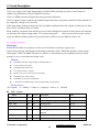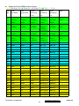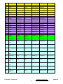
1
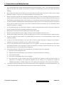
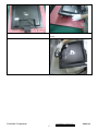
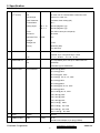
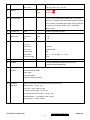
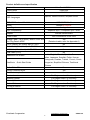
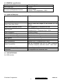
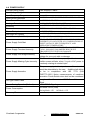
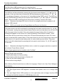
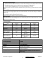
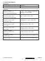
Service Manual
ViewSonic VG921m-4
Model No. VS11369
19” Color TFT LCD Display
(VG921m-4_SM Rev. 1a Nov. 2006)
ViewSonic 381 Brea Canyon Road, Walnut, California 91789 USA - (800) 888-8583
Copyright
Copyright © 2006 by ViewSonic Corporation. All rights reserved. No part of this publication
may be reproduced, transmitted, transcribed, stored in a retrieval system, or translated into any
language or computer language, in any form or by any means, electronic, mechanical, magnetic,
optical, chemical, manual or otherwise, without the prior written permission of ViewSonic
Corporation.
Disclaimer
ViewSonic makes no representations or warranties, either expressed or implied, with respect to
the contents hereof and specifically disclaims any warranty of merchantability or fitness for any
particular purpose. Further, ViewSonic reserves the right to revise this publication and to make
changes from time to time in the contents hereof without obligation of ViewSonic to notify any
person of such revision or changes.
Trademarks
Optiquest is a registered trademark of ViewSonic Corporation.
ViewSonic is a registered trademark of ViewSonic Corporation.
All other trademarks used within this document are the property of their respective owners.
Revision History
Revision
SM Editing Date
1a
11/1/2006
ViewSonic Corporation
ECR Number
Description of Changes
Initial Release
i
Editor
Jamie Chang
Confidential - Do Not Copy
VG921m-4
TABLE OF CONTENTS
1.
Precautions and Safety Notices
1
2.
Specification
4
3.
Front Panel Function Control Description
18
4.
Circuit Description
24
5.
Adjustment Procedure
31
6.
Troubleshooting Flow Chart
55
7.
Recommended Spare Parts List
63
8.
Exploded Diagram and Exploded Parts List
66
9.
Block Diagram
68
10. Schematic Diagrams
69
11. PCB Layout Diagrams
75
ViewSonic Corporation
ii
Confidential - Do Not Copy
VG921m-4
1. Precautions and Safety Notices
1.
Please carefully read this manual before operating the device and keep it available for future reference.
2.
To avoid the danger of the monitor falling and thereby possibly causing injury and/or serious damage to the monitor
itself, do not place it on unstable cars or desks. Be careful to avoid placing any stress on the LCD screen during
handling.
3.
Do not place this monitor in areas that are wet or where water or other liquids may come in contact with it, such as
bathrooms, kitchens, wet floors, near washing machines or by swimming pools.
4.
Remove the power plug from the electrical socket before cleaning. No water-containing cleaning agent should be
used to clean the screen, but only cleaning agents formulated specifically for cleaning LCD screens. Do not put any
liquid cleaning agent directly on the screen, but put it on a soft cloth first and then gently apply the cloth to the screen.
5.
In order to guarantee reliable operation and adequate heat dissipation, do not cover or block vent holes on the monitor.
Do not put the monitor close to heat sources. Do not place the monitor on furniture such as a bookshelf, unless
sufficient ventilation is available.
6.
A 3-pin grounding plug is provided for this monitor. In order to guarantee normal operation and safety of this unit,
this plug should be used with a matching grounded power socket.
7.
Please follow all warnings and instructions that accompany the monitor.
8.
Please pay special attention to power supply overloads, as electrical shock or fire may occur.
9.
Do not place anything on the power cord. Do not hang the power cord over an area where people or objects may pass.
10.
In case the monitor is not be used for an extended period, turn off power to avoid the possibility of short circuits
caused by lightning.
11.
In order to avoid electrical shock or fire risks, do not insert any object through any openings in the monitor’s
enclosure. Do not allow any liquid to come in contact with the monitor.
12.
In case of any abnormal noise or odor caused by incorrect operation, turn off power immediately and contact a
professional technician. Do not attempt to repair this monitor by yourself, as electrical shock may occur when
opening the back cover or accessing internal components.
13.
If any of the following conditions occurs, turn off power and contact a repair service provider:
1)
the power cord is damaged or worn;
2)
liquid has gotten into the monitor, or the monitor has experienced immersion or wetting;
3)
the monitor has fallen;
4)
the monitor’s performance shows obvious changes;
5)
the monitor fails to work normally when correct procedures are followed. In that case, please make any
adjustments in accordance with instructions supplied with the monitor; do not attempt any changes to
established procedures, as further damage may occur, making successful repair of the monitor more difficult.
14.
In case parts need to be replaced, you must use identical parts or those supplied by our certified manufacturers. Any
other parts used without our authorization may result in electrical shock or fire risk.
ViewSonic Corporation
1
Confidential - Do Not Copy
VG921m-4
Handing and Placing methods
Correct methods
Incorrect methods
Only touch the metal frame of the LCD panel or the
Surface of the LCD panel is pressed by fingers and that
front cover of the monitor, DO not touch the surface of
may cause”mura”
the POL
Taking out the monitor by grasping the LCD panel, that
Take out the monitor with cushions
May cause”mura”
Placing the monitor on a foreign objects, that could
Place the monitor on a clean and soft foam pad
ViewSonic Corporation
scratch The surface of the "Panel" or cause "mura"
2
Confidential - Do Not Copy
VG921m-4
The panel is placed facedown the lap,that may cause
"mura"
ViewSonic Corporation
3
Confidential - Do Not Copy
VG921m-4
2. Specification
Introduction
1
LCD PANEL
st
(1 source)
Panel:
HSD190ME13-A16
Size
19" Color a-Si TFT Active Matrix 1280x1024 LCD
Pixel Arrange
0.294 mm x 0.294 mm
Glass Treatment
Anti-Glare, Hard coating (3H)
Contrast Ratio
700 :1
Viewing Angle
CR >= 10
150/135 (degrees; typ)
CR >= 5
160/155 (degrees; typ)
Colors
16.2 million colors (6+2 bit panel)
Luminance
300 cd/m2
Response Time
On/Off
8 ms
Backlight
Backlight Life
4 CCFL
Mercury
50000 Hrs (Min)
3 mg per lamp
2
INPUT SIGNAL
RGB Analog (75 ohms, 0.7 / 1.0 Vp-p),
Video
Separate Sync / Composite Sync / SOG
3
COMPATIBILITY
Sync
Fh = 24 – 82 kHz ; Fv = 50 – 75 Hz
PC
PC Compatibles (from VGA up to 1280x1024 Non
Mac
Interlaced)
Power Mac (up to 1280X1024 )
4
RESOLUTION
Recommended
1280x1024 @ 60Hz
640 x 350 @ 70Hz
640 x 400 @ 60, 70Hz
640 x 480 @ 60, 67, 72, 75Hz
720 x 400 @ 70Hz
720 x 480 @ 60Hz
800 x 600 @ 56, 60, 72, 75Hz
832 x 624 @ 75Hz
1024 x 768 @ 60, 70, 75Hz
1152 x 864 @ 75Hz
1152 x 870 @ 75Hz
1152 x 900 @ 67Hz
1280 x 720 @ 60Hz
1280 x 768 @ 60, 75Hz
1280 x 960 @ 60, 75Hz
1280 x 1024 @ 60, 75Hz
5
AUDIO
Speaker
6
CONNECTORS
Video
1.5W x2
Analog
DB-15
Internal Power Adapter, 3-pin plug (CEE22)
ViewSonic Corporation
4
Confidential - Do Not Copy
VG921m-4
Power
7
POWER
Voltage
Consumption
AC 100-240V (Universal); 50-60 Hz
Typ/Max
32 W / 36 W
20±2 ~ -5±2 degrees
8
ERGONOMICS
Tilt
9
CONTROLS
Physical
Key buttons [PW], [Mute], [ 2 ], [Up], [Dn], [ 1 ]
OSD Function
Main Menu
Auto Image Adjust
Contrast/Brightness
Color Adjust
sRGB, 9300K, 7500K, 6500K, 5400K, User Color [R, G,
B]
Information
Manual Image Adjust
Horizontal Size, H/V Position, Fine Tune, Sharpness
Setup Menu
Language Select, Resolution Notice, OSD Position,
OSD Time Out, OSD Background
Memory Recall
Short cut key [ 1 ] : Main Menu
[ 2 ] : Auto Image Adjust
[Up] or [Dn] : Contrast / Brightness
[Up] + [Dn] : Recall both of Contrast and Brightness to
default
[ 1 ] + [ 2 ] : Toggle 720x400 and 640x400 mode
[ 1 ] + [Up] + [Dn] : Auto White Balance
[ 1 ] + [Dn] : Power Lock
[ 1 ] + [Up] : OSD Lock
10
BANDWIDTH
11
OPERATING
Temperature
32°F to 104°F (0°C to 40°C)
CONDITION
Humidity
10% to 90% (no condensation)
STORAGE /
Temperature
-4°F to 140°F (-20°C to 60°C)°
SHIPPING
Humidity
10% to 90% (no condensation)
12
135 MHz
CONDITION
13
DIMENSIONS
Physical:
Display w
425.4 mm (W) x 457.2 mm (H) x 205 mm (D)
(W x H x D)
Stand
16.75" (W) x 18" (H) x 8.1" (D)
Wall Mount
425.4 mm (W) x 397 mm (H) x 66 mm (D)
16.75" (W) x 15.6" (H) x 2.6" (D)
ViewSonic Corporation
5
Confidential - Do Not Copy
VG921m-4
14
15
Packing
497 mm (W) x 516 mm (H) x 158 mm (D)
(W x H x D)
19.6" (W) x 20.3" (H) x 6.2" (D)
WEIGHT
Net
5.3Kg (11.7 磅)
Gross
6.6kg(14.6 磅)
REGULATIONS
UL/CUL, FCC ( include ICES-003B), CB, CE, TCO'03
TUV/GS, TUV Ergo(covers ISO13406-2 & MPRII), IRAM,
VCCI, GOST-R, HYGIENIC (20 copies), Energy Star(only
test report), CCC, BSMI, PSB, C-TICK, SASO,MIC,
WEEE, RoHS
16
RELIABILITY
MTBF
17
POWER SAVING
"On"
Blue
Normal
FUNCTION
" Active Off"
Amber
≦1 W
“Off”
Off
≦1 W
Container Load
Standard
640 / 1280 pieces
18
LOGISTICS
100,000 Hr (Excluding Panel).
(20' / 40')
19
Wall Mount
20
OTHERS
Pallet Load
64 pieces
UPC Code
766907224924
Serial Format
QB9
EDID Code
Byte 10 – 0 x 1E, Byte 11 – 0 x 30
Country of origin
China
VESA
100mm x 100mm
DDC/2B, KENSINGTON MicroSaver Security
Compatible, WorldWide Model.
21
Package
LCD Display
Contents
Power CableVideo Cable
Audio Cable
Quick Start Guide
ViewSonic Wizard CD-ROM
22
Packaging
Carton -- One piece construction with signal wall, 0.65 Kg
Information
Plastic Handle -- PE-LD, 12g
Poly Foam -- EPS, 207g, 2 pices
Accessory Plastic Bags -- PE-LD, 2g
The PE bag that cover monitor -- PE-LD, 18g
Pallet (M Model ) -- Fumigation wood, 22.5Kg
Pallet (Others) -- Poplar, 22.5Kg
ViewSonic Corporation
6
Confidential - Do Not Copy
VG921m-4
Product definition and specification
Product Name
ViewSonic VG921m
Oracle item#
VG921M-4
Model Number
OSD Languages
VS11369
English, French, German, Italian, Spanish, Finnish,
Japanese, Traditional Chinese, Simplified Chinese
TFT LCD Panel and Model #
HSD190ME13-A16
Scalar
Realtek RTD2023L
Input Signal
Analog x1
Sync Compatibility
Separate Sync / Composite Sync / SOG
Adapter
Internal Power Board
Yes,
refer to APPENDIX B: Power Cable
Power Cable
Analog Cable (1.8 m, black), with PC 2001 and
Hot Plug Detect &DDC
Yes
(Detached cable; refer the Appendix A)
DVI-D Cable(1.8m, black) with PC 2001
No
Audio Cable(1.8m, black) with PC 2001
Yes
MIC Cable(1.8m, black) with PC 2001
No
USB Cable (V2.0)
No
ViewSonic CD Wizard
ViewSonic
Quick Start Guide
Arabic, English, Finnish, Spanish, German,
Italian, Japanese, Swedish, Polish, Korean,
Portuguese, Russian, Turkish , French, Czech,
Hungarian, Simplified Chinese, Traditional
Chinese
PerfectSuite CD
No
Screen Protector Mylar
Yes
Foot Protector plastic
No
Service Insert
For Region code = M units only
Warranty Sticker
For Region code = G units only
Warranty Card
For Region code = G units only
Carton Sticker
For Region code = G units only
PE bag of Carton
For Region code = G units only
ViewSonic Corporation
7
Confidential - Do Not Copy
VG921m-4
4-1 GENERAL specification
Test Resolution & Frequency
1280x1024 @ 60Hz
Test Image Size
Full Size
Contrast and Brightness Controls
Factory Default:
Contrast = 70%, Brightness = 100%
4-2 VIDEO INTERFACE
Input Connector (refer the Appendix A)
DB-15
Default Input Connector
Defaults to the first detected input
Video Cable Strain Relief
Equal to twice the weight of the monitor for five
minutes
Video Cable Connector Pin out
Refer to Appendix A; Compliant DDC/2B
Video Signals
Video RGB (Analog)
Separate Sync / Composite Sync / SOG
Video Impedance
75 Ohms (Analog)
Maximum PC Video Signal
950 mV with no damage to monitor
Maximum Mac Video Signal
1250 mV with no damage to monitor
Sync Signals
TTL
DDC/2B
Compliant with version 1.3
Sync Compatibility
Separate Sync / Composite Sync / SOG
Video Compatibility
Shall be compatible with all PC type computers,
Macintosh computers, and after market video cards
Resolution Compatibility
Refer to Segment 4-5
Exclusions
Not compatible with interlaced video
4-3 USB INTERFACE
No USB interface
ViewSonic Corporation
8
Confidential - Do Not Copy
VG921m-4
4-4 POWER SUPPLY
Internal Power Supply
Input Voltage Range
Part Number:PI-SB03
100to 240VAC
Input Frequency Range
50 to 60 Hertz
Short Circuit Protection
OUTPUT CAN BE SHORTED WITHOUT DAMAGE
Over Current Protection
6 A TYPICAL AT 5 VDC
Leakage Current
1.0 MA (MAX) AT 264VAC / 60HZ
Efficiency
80 % TYPICAL AT 115VAC FULL LOAD
Fuse
INTERNAL AND NOT USER REPLACEABLE
Power Dissipation
32 WATTS (TYP)
Max Input AC Current
1.2 ARMS @ 90VAC, 0.8 ARMS @180VAC
Inrush Current (Cold Start)
30 A @ 90 VAC, 60 A(MAX) @ 264 VAC
Power Supply Cold Start
Power Supply Transient Immunity
Power Supply Line Surge Immunity
SHALL START AND FUNCTION PROPERLY WHEN
UNDER FULL LOAD, WITH ALL COMBINATIONS OF
INPUT VOLTAGE, INPUT FREQUENCY, AND
OPERATING TEMPERATURE
SHALL BE ABLE TO WITHSTAND AN ANSI/IEEE
C62.41-1980 6000V 200 AMPERE RING WAVE
TRANSIENT TEST WITH NO DAMAGE
Shall be able to withstand 1.5 times nominal line
voltage for one cycle with no damage
Power Supply Missing Cycle Immunity
Shall be able to function properly, without reset or
visible screen artifacts, when ½ cycle of AC power is
randomly missing at nominal input
Power Supply Acoustics
The power supply shall not produce audible noise that
would be detectable by the user. Audible shall define
to be in compliance with ISO 7779 (DIN
EN27779:1991) Noise measurements of machines
acoustics. Power Switch noise shall not be considered
US Type Power Cable
Length = 1.8m. Connects to AC/DC Power Color =
Black
Power Saving Operation(Method)
VESA DPMS Signaling
Power Consumption
Recovery Time
ViewSonic Corporation
On Mode <36 W (max)
Saving Mode< 1W
Off Mode <1 W
On Mode = N/A, Active Off < 3 sec
9
Confidential - Do Not Copy
VG921m-4
4-5 ELECTRICAL REQUIREMENT
Horizontal / Vertical Frequency
Horizontal Frequency
24 – 82 kHz
Vertical Refresh Rate
50 – 75 Hz
Maximum Pixel Clock
135 MHz
Sync Polarity
Independent of sync polarity
Timing Table
SOG
Timing
Composite
Separated
Item
Digital - TMDS
Analog
Remark
1
640 x 350 @
70 Hz,
31.5 KHz
2
640 x 400 @
60 Hz,
31.5 KHz
3
640 x 400 @
70 Hz,
31.5 KHz
4
640 x 480 @
50 Hz,
24.7 KHz
5
640 x 480 @
60 Hz,
31.5 KHz
6
640 x 480 @
67 Hz,
35 KHz
7
640 x 480 @
72 Hz,
37.9 KHz
DMT
8
640 x 480 @
75 Hz,
37.5 KHz
DMT
9
720 x 400 @
70 Hz,
31.5 KHz
10
720 x 480 @
60 Hz,
31.5 KHz
DTV
11
720 x 576 @
50 Hz,
31.3 KHz
DTV
12
800 x 600 @
56 Hz,
35.1 KHz
DMT
13
800 x 600 @
60 Hz,
37.9 KHz
DMT
14
800 x 600 @
72 Hz,
48.1 KHz
DMT
15
800 x 600 @
75 Hz,
46.9 KHz
DMT
16
832 x 624 @
75 Hz,
49.7 KHz
MAC
17
1024 x 768 @
50 Hz,
39.6 KHz
18
1024 x 768 @
60 Hz,
48.4 KHz
DMT
19
1024 x 768 @
70 Hz,
56.5 KHz
DMT
21
1024 x 768 @
75 Hz,
60 KHz
DMT
23
1152 x 864 @
75 Hz,
67.5 KHz
DMT
24
1152 x 870 @
75 Hz,
68.7 KHz
For MAC
25
1152 x 900 @
67 Hz,
62.5 KHz
For SUN
26
1280 x 720 @
50 Hz,
37.5 KHz
DTV
27
1280 x 720 @
60 Hz,
45 KHz
DTV
28
1280 x 768 @
50 Hz,
39.6 KHz
29
1280 x 768 @
60 Hz,
47.8 KHz
DMT;
30
1280 x 768 @
75 Hz,
60.3 KHz
DMT;
ViewSonic Corporation
DMT
DMT
For MAC
10
Confidential - Do Not Copy
VG921m-4
31
1280 x 960 @
50 Hz,
49.4 KHz
32
1280 x 960 @
60 Hz,
59.7 KHz
33
1280 x 960 @
75 Hz,
75.2 KHz
34
1280 x 1024 @
50 Hz,
52.7 KHz
35
1280 x 1024 @
60 Hz,
64 KHz
DMT
36
1280 x 1024 @
75 Hz,
80 KHz
DMT
DMT
*1. Tolerance ≧ ±2KHz (if no overlapping issue)
*2. Any timing not in the list, it should display as normal or show on “OUT OF RANGE” OSD message without
blanking.
*3. The image quality of 85Hz mode might be worse than 75Hz.
Primary Presets
1280x1024 @ 60Hz
User Presets
Number of User Presets (recognized timings) Available: 10 presets total in FIFO configuration
Changing Modes
● Maximum Mode Change Blank Time for image stability : 5 seconds (Max), excluding “Auto
Adjust” time
● Under DOS mode (640 x 350, 720 x 400 & 640 x 400),
execute “Auto Adjust”
it should recall factory setting when
● The monitor needs to do “Auto Adjust” the first time a new mode is detected
(see section “0-Touch™ Function Actions”)
● While running Change Mode, Auto Adjust or Memory Recall, the image shall blank
ViewSonic Corporation
11
Confidential - Do Not Copy
VG921m-4
4-6 FRONT PANEL CONTROLS AND INDICATORS
Front Panel Hardware Controls
Power Switch (Front Head)
Power Control, soft Power Switch.
Power LED (Front Head)
Green – ON
Orange – Power Saving Mode
Dark = Soft Power Switch OFF
Front Panel Controls (Head)
[ ] [ 1 ] [ 2 ] [▲] [▼]
[;X] Mute
[ ] Power
[ 1 ] BUTTON 1
[ 2 ] Button 2
[▲] UP ARROW BUTTON
[▼] DOWN ARROW BUTTON
Note: Power Button, Button 1 and Button 2 must be
one-shot logic operation. (i.e. there should be no
cycling)
Reaction Time
OSD must fully appear within 0.5s after pushing Button
1
Short Cuts Function from the button(s)
[1]
Main Menu
[2]
Auto Image Adjust
[▼]
Brightness adjust
[▲]
Contrast
adjust
[▼]+ [▲]
recall both of Contrast and Brightness to default
[1] + [2]
1. toggle 720x400@70Hz/640x400@70Hz mode when input one
of the two mode
2. toggle 640x480@60Hz/640x400@60Hz mode when input one
of the two mode
[1] + [▼] + [▲]
White Balance. (Not shown on user’s guide)
[1] + [▼]
Power Lock
[1] + [▲]
OSD Lock
No signal + [2] + [ ]
Burning mode
Signal + [2] + [ ]
Factory Mode
Remark : All the short cuts function are only available while OSD off
ViewSonic Corporation
12
Confidential - Do Not Copy
VG921m-4
Function descriptions
Main Menu Controls
The Main Menu OSD includes most of control functions.
Please refer to APPENDIX C (Main Menu OSD Table) for the detail.
OSD Lock short cuts function for the buttons
The OSD lock will be activated by pressing the front panel control buttons "(1), & (▲)" for 10
seconds. If the user then tries to access the OSD by pressing any of the buttons "1", "▼", "▲",
"2" a message will appear on the screen for 3 seconds showing "OSD Locked". The OSD lock
will be deactivated by pressing the front panel control buttons "(1), & (▲)" again for 10 seconds.
Note1: When the OSD is locked will lock all functions, including “Volume” and “Mute”
Note 2: Status bar indicating OSD Lock or Unlock is in progress and when complete it will
indicate “OSD Locked”
Note 3: OSD Lock should not lock Power Button and Power Lock function
Power Lock short cuts function for the buttons
The power button lock will be activated by pressing the front panel control buttons "(1), & (▼)"
for 10 seconds. Locking the power button means that the user won't be able to turn off the LCD
while the power button is locked. If the user presses the power button while it is locked, a
message will appear on the screen for 3 seconds showing "Power Button Locked". It also
means that with the power button locked, the LCD would automatically turn back "On" when
power is restored after a power failure. If the power button is not in the locked mode, then power
should return to it's previous state when power is restored after a power failure. The power
button lock will be deactivated by pressing the front panel control buttons "(1), & (▼)" again for
10 seconds.
Note 1: Status bar indicating Power Button lock or unlock is in progress and when complete it
will indicate “Power Button Locked”
Note 2: Power should only be lockable in the “On State”
Memory Recall Actions
Memory Recall action as below
1. Recall white balance to factory setting
2. Set the factory defaults as shown in Section 4-8
3. Clean all the mode setting buffer
4. Execute Auto Image Adjust
Note: Memory Recall should have no effect for Language, Power Lock, User Color Settings or
Input Priority
Input Signal Notice Actions
1. The Input Signal Notice OSD appears 3 seconds when power turns on or change input
signal.
2. The Input Signal Notice OSD position is on the right-bottom side of image. And the OSD
background shall be transparent. (OSD Background = off).
ViewSonic Corporation
13
Confidential - Do Not Copy
VG921m-4
Resolution Notice Actions
1. Resolution Notice OSD should show on screen after changing to non-native mode for 30 sec
2. For auto input select function, it shall meet the requirement in Appendix D.
3. The OSD should disappear after 10 sec or by pushing button [1] or [2]
Resolution Notice function should be disabled when push button [2] under Resolution Notice
OSD
0-Touch™ Function Actions
1. Execute Auto Image Adjust when new mode detected, and save the settings to buffer for
further use
2. It should be reset by Memory Recall function
(Should not reset by power off, power unplug and others)
OSD Auto Save
The OSD shall save new settings when it is turned off by the user or when it times out. There
shall not be a separate save
Factory Defaults
Item
Defaults
Item
Defaults
Contrast
70%
Input Priority
N/A
Brightness
100%
Resolution Notice
On
Color Temperature
6500K
Volume
50%
Sharpness
100%
Balance
N/A
OSD H. Position
50%
Treble
N/A
OSD V. Position
50%
Bass
N/A
OSD Time Out
15
720x400 / 640x400
(@70Hz)
720x400
OSD Background
On
640x480 / 640x400
(@60Hz)
640x480
4-7 AUDIO INTERFACE (SPEAKER SPECIFICATION)
Speaker specification
Line input connection
Line input signal
Line input impedance
Maximum power output (Electric)
Signal to Noise Ratio
Frequency response
Distortion
Vibration
Screen image
Connector PC99 requirement Audio in
Cable type / length
Audio DPMS
3.5 mm stereo jack
1.0 Vrms
10 kOhm
1.5 W / ch
50 dB
200 Hz – 20 Khz(-10db)
< 15 % THD (@1kHz)
There should be no audible vibration with volume at 100%
and treble / bass at default.
There should be no affect on the screen image stability
under any conditions.
Lime Green pantone # 577C
3.5mm stereo cable / 1.8m length
Speakers should be off when the rest of the monitor is in
power saving.
* No any sympathetic or abnormal noise allowed.
ViewSonic Corporation
14
Confidential - Do Not Copy
VG921m-4
4-8 TFT LCD PANEL
Panel Characteristics :
1st Source Panel
Model number
HSD190ME13-A16
Type
Active Matrix TFT, TN technology
Active Size
19” (337.8mm x 301mm)
Pixel Arrangement
RGB Vertical Stripe
Pixel Pitch
0.294 mm
Glass Treatment
Anti-Glare, Hard coating (3H)
# of Backlights
4 CCFL
Backlight Life
50000 Hrs (Min)
Luminance (Center) –
300 cd/m2 (Typ after 30 minute warm up)
240 cd/m2 (Min after 30 minute warm up)
CT = 6500K,
Contrast/ Brightness = Max
Brightness Uniformity (13 points)
80 % (Typ) / 75 % (Min)
Contrast Ratio
700 :1 (Typ)
450 : 1 (Min)
Color Depth
16.2 million colors (6+2 bit panel)
Horizontal Viewing Angle
150 degrees (Typ) / 130 degrees (Min) @ CR>10
160 degrees (Typ) / TBD (Min) @ CR>5
Vertical Viewing Angle
135 degrees (Typ) / 110 degrees (Min) @ CR>10
TBD degrees (Typ) / TBD (Min) @ CR>5
Response Time
10%-90% @ Ta=25°C
On-Off
8ms (Typ) / 16ms (Max)
Mercury
3.0 mg per lamp
Panel Defects
Please see Panel Quality Specifications.
*Over 50% units of shipment shall be equal or better than the Typical value above.
ViewSonic Corporation
15
Confidential - Do Not Copy
VG921m-4
4-9 IMAGE PERFORMANCE
Display Size
Horizontal Display Size, Primary Preset Full Screen
Vertical Display Size, Primary Preset
Full Screen
Luminance
Lv (Max) –Condition:
Brightness / Contrast = 100%
CCT = USER COLOR (R/G/B=100%)
Lv (Max) = The Luminance requirement of
section 4-6 “TFT LCD PANEL”
Lv (Def) –Condition:
Brightness / Contrast = 100%
Lv (Def) / Lv (Max) x 100% > 95%
Color Temperature = 6500K / sRGB
Lv (sRGB/6500K) –Condition:
Brightness / Contrast = Default
Lv (sRGB/6500K) / Lv (Max) x 100% > 85%
CCT = 6500K / sRGB
Lv (9300K) –Condition:
Brightness / Contrast = Default
Lv (9300K) / Lv (Def) x 100% > 70%
CCT = 9300K
Lv (7500K) –Condition:
Brightness / Contrast = Default
Lv (7500K) / Lv (Def) x 100% > 80%
CCT = 7500K
Lv (5400K) –Condition:
Brightness / Contrast = Default
Lv (5400K) / Lv (Def) x 100% > 85%
CCT = 5400K
Lv (Brightness) –Condition:
Contrast = 100%
Lv (Contrast) –Condition:
Brightness = 100%
ViewSonic Corporation
Lv(Brightness=0%) / Lv(Brightness=100%) x 100% ≤ 55%
Lv(Contrast=0%) / Lv(Contrast=100%) x 100% ≤ 30%
16
Confidential - Do Not Copy
VG921m-4
Contrast Ratio
CR(Max) –Condition:
Contrast / Brightness = 100%
CCT = USER COLOR (R/G/B=100%)
Same as the Contrast Ratio in section 4-6
“TFT LCD PANEL”
CR(6500K) –Condition:
Contrast / Brightness = Default
CR(6500K) / CR(Max) ≧ 85%
CCT = 6500K
Saturation
Contrast = Default
Brightness = Default
Test pattern = 128-gray
Contrast = 100%
Brightness = 100%
Test pattern = 64-gray
NO VISIBLE SATURATION
* ≧50% UNITS OF SHIPMENT SHALL BE
EQUAL OR BETTER THAN TYPICAL CR
SPEC.
6~8 - LEVEL SATURATION
Preset Color Temperatures
sRGB
It should meet IEC 61966-2-1 (1999-10) standard.
Preset 1
CCT (typ) = 9300K (u’CCT=0.1888; v’ CCT=0.4457)
CCT (max) = 10250K, CCT (min) = 8500K
Δu’v’<0.01 (@ Full White pattern)
Preset 2
CCT (typ) = 7500K (u’CCT=0.1935; v’ CCT=0.4586)
CCT (max) = 8100K, CCT (min) = 6980K
Δu’v’<0.01 (@ Full White pattern)
Preset 3 (Primary)
CCT (typ) = 6500K (u’CCT=0.1978; v’ CCT=0.4684)
CCT (max) = 6950K, CCT (min) = 6100K
Δu’v’<0.01 (@ Full White pattern)
Preset 4
CCT (typ) = 5400K (u’CCT=0.2044; v’ CCT=0.4808)
CCT (max) = 6185K, CCT (min) = 4935K
Δu’v’<0.01 (@ Full White pattern)
Preset Color Temperature
Adjustability
Each color preset shall be adjustable.
and Blue shall be individually controlled.
Red, Green,
* Any gray level and Contrast/Brightness should not get reddish, greenish or bluish.
ViewSonic Corporation
17
Confidential - Do Not Copy
VG921m-4
3. Front Panel Function Control Description
Adjusting the Screen Image
Use the buttons on the front control panel to display and adjust the OSD controls which display
on the screen. The OSD controls are explained at the top of the next page and are defined in
“Main Menu Controls” on page 10.
Main Menu
with OSD controls
Front Control Panel
shown below in detail
Standby Power On/Off
Power light
Blue = ON
Orange = Power Saving
Audio Mute button turns the sound off
Displays the Main Menu or exits the control screen and saves
adjustments.
Scrolls through menu options and adjusts the displayed control.
Also a shortcut to display the Contrast adjustment control screen.
Displays the control screen for the highlighted control.
Also a shortcut to Auto Image Adjust.
ViewSonic Corporation
18
Confidential - Do Not Copy
VG921m-4
Do the following to adjust the display setting:
1. To display the Main Menu, press button [1].
NOTE: All OSD menus and adjustment screens disappear automatically after about 15
seconds. This is adjustable through the OSD timeout setting in the setup menu.
2. To select a control to adjust, pressSorTto scroll up or down in the Main Menu.
3. After the desired control is selected, press button [2]. A control screen like the one shown
below appears.
The command line at the bottom of the
control screen tells what to do next from
this screen. You can toggle between control
screens, adjust the selected option, or exit
the screen.
4. To adjust the setting, press the up S or down T buttons.
5. To save the adjustments and exit the menu, press button [1] twice.
The following tips may help you optimize your display:
• Adjust the computer's graphics card so that it outputs a 1280 x 1024 @ 60Hz video signal to
the LCD display. (Look for instructions on “changing the refresh rate” in the graphics card's
user guide.)
• If necessary, make small adjustments using H. POSITION and V. POSITION until the
screen image is completely visible. (The black border around the edge of the screen should
barely touch the illuminated “active area” of the LCD display.)
ViewSonic Corporation
19
Confidential - Do Not Copy
VG921m-4
Main Menu Controls
Adjust the menu items shown below by using the up S and down T buttons.
Control
Explanation
Auto Image Adjust sizes and centers the screen image automatically.
Contrast adjusts the difference between the image background (black level)
and the foreground (white level).
Brightness adjusts background black level of the screen image.
Audio Adjust
Volume increases the volume, decreases the volume, and mutes the audio.
Mute temporarily silences audio output.
Color Adjust provides several color adjustment modes, including preset color
temperatures and a User Color mode which allows independent adjustment of
red (R), green (G), and blue (B). The factory setting for this product is 6500K
(6500 Kelvin).
sRGB-This is quickly becoming the industry standard for color management,
with support being included in many of the latest applications. Enabling this
setting allows the LCD display to more accurately display colors the way they
were originally intended. Enabling the sRGB setting will cause the Contrast and
Brightness adjustments to be disabled.
9300K-Adds blue to the screen image for cooler white (used in most office
settings with fluorescent lighting).
6500K-Adds red to the screen image for warmer white and richer red.
5400K-Adds green to the screen image for a darker color.
5000K-Adds blue and green to the screen image for a darker color.
ViewSonic Corporation
20
Confidential - Do Not Copy
VG921m-4
Control
Explanation
User Color Individual adjustments for red (R), green (G), and blue (B).
1. To select color (R, G or B) press button [2].
2. To adjust selected color, pressSandT.
Important: If you select RECALL from the Main Menu when the product is
set to a Preset Timing Mode, colors return to the 6500K factory preset.
Information displays the timing mode (video signal input) coming from the
graphics card in the computer, the LCD model number, the serial number, and
the ViewSonic® website URL. See your graphics card’s user guide for
instructions on changing the resolution and refresh rate (vertical frequency).
NOTE: VESA 1280 x 1024 @ 60Hz (recommended) means that the resolution
is 1280 x 1024 and the refresh rate is 60 Hertz.
Manual Image Adjust
H. Size (Horizontal Size) adjusts the width of the screen image.
H./V. Position (Horizontal/Vertical Position) moves the screen image left or
right and up or down.
ViewSonic Corporation
21
Confidential - Do Not Copy
VG921m-4
Control
Explanation
Fine Tune sharpens the focus by aligning text and/or graphics with pixel
boundaries.
NOTE: Try Auto Image Adjust first.
Sharpness adjusts the clarity and focus of the screen image.
Setup Menu displays the menu shown below:
Language Select allows the user to choose the language used in the menus and
control screens.
Resolution Notice allows the user to enable or disable this notice.
If you enable the Resolution Notice shown above and your computer is set at a
resolution other than 1280 x 1024, the following screen appears.
ViewSonic Corporation
22
Confidential - Do Not Copy
VG921m-4
Control
Explanation
OSD Position allows the user to move the OSD menus and control screens.
OSD Timeout sets the length of time the OSD screen is displayed. For example,
with a “30 second” setting, if a control is not pushed within 30 seconds, the
display screen disappears.
OSD Background allows the user to turn the OSD background On or Off.
Memory Recall returns the adjustments back to factory settings if the display is
operating in a factory Preset Timing Mode listed in the Specifications of this
manual.
ViewSonic Corporation
23
Confidential - Do Not Copy
VG921m-4
4. Circuit Description
A. AC-DC CONVERTER
The power supply with a high-integrated green-mode PWM controller provides several features to
enhance the performance of power flyback converters.
U801 is a PWM controller and provides many protection functions.
U802 is a photo couple to transfer the feedback signal from the second side which U803 detected both of
the output DC voltage on 5V and 24V.
Z802 detected the working voltage on U801 and Q802 would pull down the voltage on U801 pin5 to shut
down U801 if feedback loop was failed.
R828 would be a dynamic load which was active while backlight was turned off and system still working
on, this kept 24V output voltage under 32V to protect the panel.
After system went to power saving
mode, the R828 would no loaded. This was detected by Z803 active the R828 to load or not.
B,Scaling Controller
Overview
Realtek RTD2523B series products are all-in-one LCD monitor controllers support up to
SXGA/XGA(optional), and integrate Realtek high performance ADC, TMDS Rx(optional), scaling engine,
OSD engine, LVDS TX, RSDS TX and so on. Moreover, all products are pin compatible in low pin count
package to save cost and make the design easier
General
Embedded dual DDC support DDC1, DDC2B, DDC/CI
Zoom scaling up and down
Embedded Pattern Generator
No external memory required.
Require only one crystal to generate all timing
Embedded reset control output
Embedded crystal output to MICROP
3 channels 8 bits PWM output, and selectable PWM clock frequency.
Pin Description
(I/O Legend: A = Analog, I = Input, O = Output, P = Power, G = Ground)
ADC: 15 pins
Name
I/O
Pin No
Description
Note
ADC_GND
AG
27
ADC ground
ADC_REFIO
AP
28
ADC band-gap voltage de-coupling
1.20V
ADC_VDD
AP
29
Analog power
(3.3V)
BLUE+
AI
30
Analog input from BLUE channel
BLUE-
AI
31
Analog input ground from BLUE
channel
ADC_GND
AG
32
ADC ground
SOG/ADC_TEST
AIO
33
SOG in/ADC test pin
ViewSonic Corporation
24
Confidential - Do Not Copy
VG921m-4
GREEN+
AI
34
Analog input from GREEN channel
GREEN-
AI
35
Analog input ground from GREEN
channel
ADCB_VDD
AP
36
Analog power
(3.3V)
RED+
AI
37
Analog input from RED channel
RED-
AI
38
Analog input ground from RED
channel
ADC_GND
AG
39
Analog ground
ADC_GND
AG
40
Analog ground
ADC_VDD
AP
41
Analog power
(3.3V)
AHS
AI
42
Analog HS input
(10), (4), (5)
AVS
AI
43
Analog VS input
(2), (4), (5)
I/O
Pin No
Description
Note
XO
AI
1
Reference clock output
XI
AO
2
Reference clock input
DPLL_GND
AG
3
Ground for digital PLL
DPLL_VDD
AP
4
Power for digital PLL
(3.3V)
APLL_VDD
AP
5
Power for multi-phase PLL
(3.3V)
PLL_TEST1
AIO
6
Test Pin 1 / IRQ#
PLL_TEST2
AIO
7
Test Pin 2/Power-on-latch for crystal
PLL: 8 pins
Name
out Frequency
APLL_GND
AG
8
Ground for multi-phase PLL
I/O
Pin No
Description
Note
IO
54
Serial control I/F data in / Parallel port
(2), (3), / 2mA
Control Interface: 7 pins
Name
SDIO [0]
data [0]
SDIO [1] / TCON [4] /
IO
53
BBLU [0]
SDIO [2] / TCON [3] /
(1), (2), (3), / 2mA
BBLU [0]
IO
52
BBLU [1]
SDIO [3] / PWM2 /
Parallel port data [1] / TCON [4] / TTL
Parallel port data [2] / TCON [3] / TTL
(1), (2), (3), / 2mA
BBLU [1]
IO
51
TCON [2]
Parallel port data [1] / TCON [4] /
(1), (2), (3), / 2mA
PWM2
SCLK
I
50
Serial control I/F clock
(2), (3), (5)
SCSB
I
111
Serial control I/F chip select
(2), (3), (5)
56
RESET output for Micron
(2), (5), (6) / 2mA
RESET
O
ViewSonic Corporation
25
Confidential - Do Not Copy
VG921m-4
Display & TCON/VIDEO-8 Port: 54 pins
■:LVDS+RSDS+TTLO ■:RSDS+TTLO ■:RSDS+TTLIO■:TTLO ■:TTLIO
Pin
6-bits
6 bits
8/6 bits
8 bits
6 bits
NO.
Dual RSDS
Single RSDS
Dual/Single
Dual/Single
Dual/Single
LVDS
TTL
TTL
51
52
Note
S[3] /
S[3] /
S[3] /
S[3] /
S[3] /
(1), (2), (3)/
TCON[2] /
TCON[2] /
TCON[2] /
TCON[2] /
TCON[2] /
2mA
PWM2
PWM2
PWM2
PWM2
PWM2
S[2] /
S[2] /
S[2] /
TCON[3]
TCON[3]
TCON[3]
S[2]
/BBLU[1] /
S[2] /
(1), (2), (3)/
TCON[3]
2mA
TCON[3]
53
S[1] /
S[1] /
S[1] /
S[1]/ BBLU[0]
S[1] /
(1), (2), (3)/
TCON[4]
TCON[4]
TCON[4]
/ TCON[4]
TCON[4]
2mA
PWM2 /
PWM2 /
PWM2 /
PWM2 /
PWM2 /
(1), (2), (3)/
COUT /
COUT /
COUT /
COUT /
COUT /
2mA
TCON[13]
TCON[13]
TCON[13]
TCON[13]
TCON[13]
59
BB3P
BB3P
NC
BBLU [7]
BBLU [7]
60
BB3N
BB3N
NC
BBLU [6]
BBLU [6]
61
BB2P
BB2P
NC
BBLU [5]
BBLU [5]
62
BB2N
BB2N
NC
BBLU [4]
BBLU [4]
63
BB1P
BB1P
NC
BBLU [3]/T0
BBLU [3]
64
BB1N
BB1N
NC
BBLU [2]/T1
BBLU [2]
65
BCLKP
BCLKP
NC
BGRN [1]/T2
TCON [6]
66
BCLKN
BCLKN
NC
BGRN [0]/T3
TCON [5]
67
BG3P
BG3P
NC
BGRN [7]
BGRN [7]
68
BG3N
BG3N
NC
BGRN [6]
BGRN [6]
73
BG2P
BG2P
TODP
BGRN [5]/T4
BGRN [5]
74
BG2N
BG2N
TODN
BGRN [4]/T5
BGRN [4]
75
BG1P
BG1P
TOCLKP
BGRN [3]/T6
BGRN [3]
76
BG1N
BG1N
TOCLKN
BGRN [2]/T7
BGRN [2]
77
BR3P
BR3P
TOCP
BRED [7]/T8
BRED [7]
78
BR3N
BR3N
TOCN
BRED [6]/T9
BRED [6]
79
BR2P
BR2P
TOBP
BRED [5]/T10
BRED [5]
80
BR2N
BR2N
TOBP
BRED [4]/T11
BRED [4]
81
BR1P
BR1P
TOAP
BRED [3]/T12
BRED [3]
82
BR1N
BR1N
TOAP
BRED [2]/T13
BRED [2]
85
AB3P
NC
TEDP
ABLU [7]/T14
ABLU [7]
86
AB3N
NC
TEDN
ABLU [6]/T15
ABLU [6]
87
AB2P
NC
TECLKP
ABLU [5]/T16
ABLU [5]
55
ViewSonic Corporation
26
Confidential - Do Not Copy
VG921m-4
88
AB2N
NC
TECLKN
ABLU [4]/T17
ABLU [4]
89
AB1P
NC
TECP
ABLU [3]/T18
ABLU [3]
90
AB1N
NC
TECN
ABLU [2]/T19
ABLU [2]
91
ACLKP
NC
TEBP
ABLU [1]/T20
TCON [1]
92
ACLKN
NC
TEBN
ABLU [0]/T21
TCON [0]
93
AG3P
NC
TEAP
AGRN [7]/T22
AGRN [7]
94
AG3N
NC
TEAN
AGRN [6]/T23
AGRN [6]
99
AG2P
TCON [11]
NC
AGRN [5]/T24
AGRN [5]
100
AG2N
TCON [10]
NC
AGRN [4]/T25
AGRN [4]
101
AG1P
TCON [9]
NC
AGRN [3]/T26
AGRN [3]
102
AG1N
TCON [8]
NC
AGRN [2]/T27
AGRN [2]
103
AR3P
TCON [7]
NC
ARED [7]/T28
ARED [7]
104
AR3N
TCON [6]
NC
ARED [6]/T29
ARED [6]
105
AR2P
TCON [5]
NC
ARED [5]/TH
ARED [5]
106
AR2N
TCON [1]
NC
ARED [4]/TV
ARED [4]
107
AR1P
TCON [0]
NC
ARED [3]/TE
ARED [3]
108
AR1N
NC
NC
ARED [2]/TK
ARED [2]
113
PWM2 /
PWM2 /
PWM2 /
ARED [1]
PWM2 /
COUT /
COUT /
COUT /
COUT /
TCON[12]
TCON[12]
TCON[12]
TCON[12]
TCON [11]
V [0]
V [0]
ARED [0]
TCON [11]
(1), (7), (8)
V [1]
V [1]
BRED [1]
TCON [10]
(1), (7), (8)
V [2]
V [2]
BRED [0]
TCON [9]
(1), (7), (8)
V [3]
V [3]
AGRN [1]
TCON [8]
(1), (7), (8)
V [4]
V [4]
AGRN [0]
TCON [7]
(1), (7), (8)
V [5]
V [5]
DHS
DHS
(1), (7), (8)
V [6]
V [6]
DVS
DVS
(1), (7), (8)
V [7]
V [7]
DENA
DENA
(1), (7), (8)
VCLK
VCLK
DCLK / TCLK
DCLK / TCLK
(1), (7), (8)
114
(9)
/V[0]
115
TCON [10]
/V[1]
116
TCON [9] /
V[2]
117
TCON [8] /
V[3]
118
TCON [7] /
V[4]
119
TCON [6] /
V[5]
122
TCON [5] /
V[6]
123
TCON [1] /
V[7]
124
TCON [0] /
VCLK
ViewSonic Corporation
27
Confidential - Do Not Copy
VG921m-4
TMDS: 18 pins
Name
TMDS_TST/ PWM1
I/O
Pin No
Description
Note
AIO
9
TMDS_TEST Pin / PWM1 / Power-on-latch for serial /
parallel port
TMDS_GND
G
10
TMDS_VDD
P
11
EXT_RES
A
12
TMDS_VDD
P
13
RX2P
I
14
Differential Data Input
RX2N
I
15
Differential Data Input
TMDS_GND
G
16
RX1P
I
17
Differential Data Input
RX1N
I
18
Differential Data Input
TMDS_VDD
P
19
RX0P
I
20
Differential Data Input
RX0N
I
21
Differential Data Input
TMDS_GND
G
22
RXCP
I
23
Differential Data Input
RXCN
I
24
Differential Data Input
TMDS_GND
G
25
TMDS_VDD
P
26
(3.3V)
Impedance Match Reference.
(3.3V)
(3.3V)
(3.3V)
PWM Interface: 3-2=1 pin (PWM1, PWM2 can be selected from 1 of 3 possible pins.)
Name
I/O
Pin No
Description
Note
PWM2 / TCON [2] / S [3]
O
51
PWM2 / TCON [2] / SDIO [3]
(1), (2), (3), (5), (8),
PWM2 / TCON [13] / COUT
O
55
PWM2 / TCON [13] / Crystal out
(2), (8), (9)
PWM2 / TCON [12] / COUT
O
113
PWM2 / TCON [12] / Crystal out
(2), (8), (9)
PWM1 / TMDS_TST
AIO
9
PWM1/ TMDS_TEST Pin /
(2), (7), (8)
Power-on-latch for serial / parallel port
PWM1 / DDCSDA / TCON [1] /
IO
47
BBLU [0]
PWM1 / DDCSDA2 (HDCP) /
(1), (2), (3), (5), (8),
input / output / TCON [4]
IO
125
TCON [7]
PWM0 / REFCLK
PWM1 / DDC serial control I/F data
PWM1 / DDC serial control I/F data
(1), (2), (3), (5), (8),
input / output / TCON [7]
IO
112
PWM0 / (In / out) test pin for DCLK /
(2), (9)
Video8 even-odd signal
DDC Channel: 4 pins
Name
DDCSCL / TCON [0] / BBLU
[1]
ViewSonic Corporation
I/O
Pin No
Description
Note
I
46
DDC serial control I/F clock / TCON
(2), (3), (5)
[0] / TTL BBLU [1]
28
Confidential - Do Not Copy
VG921m-4
DDCSDA / TCON [1] / PWM1 /
IO
47
BBLU [0]
DDC serial control I/F data input /
(1), (2), (3), (5), (6),
output / TCON [1] / PWM1 / TTL BBLU
(8)/ 8mA /no slew
[0]
DDCSCL2 (HDCP) / TCON [5]
I
126
DDC serial control I/F clock / TCON
(2), (3), (5)
[5]
DDCSDA2 (HDCP) / TCON [7]
IO
125
/PWM1
DDC serial control I/F data input /
(1), (2), (3), (5), (6),
output / TCON [7] / PWM1
(8)/ 8mA /no slew
Power & Ground: 22 pins
Name
I/O
Pin No
Description
3.3V Power
P
49,121
VCCIO: 2
3.3V Ground
G
48,120
GNDIO: 2
3.3V Power
P
58,71,83,95,110
PVCC: 5
3.3V Ground
G
57,72,84,96,109
PGND: 5
2.5V Power
P
45,69,98,127
VCCK: 4
2.5V Ground
G
44,70,97,128
GNDIK: 4
Note: (1) TTL compatible CMOS Input (Vt=1.7V); VCC=3.3V;
(2) 5V tolerance pad;
(3) Internal 75K Ohms pull high resistor.
(4) Internal 75K Ohms pull low resistor.
(5) Schmitt trigger CMOS Input (Vt=1.4-~2.2V);
(6) Open-Drain, Output Drive low & Pull-high.
(7) Bi-directional input/output
(8) Programmable driving current (2~10mA)
(9) TTL output 5V & 3.3V
(10) 4V tolerance pad
C, MTV512M
The MTV512M micro-controller is an 8051 CPU core
embedded device especially tailored for flat panel
display applications. It includes an 8051 CPU core,
768-byte SRAM, 4 channels of 6-bit ADC, 3 external
counters/timers, 6 channels of PWM DAC, VESA
DDC interface, and a 64K-byte internal program
Flash-ROM memory in 44-pin PLCC package
FEATURES
• 8051 core, 12MHz operating frequency with
single/double CPU clock option
• 0.35um process; 3.3V power supply
• 768-byte RAM; 64K-byte program Flash memory
• Maximum 6 channels of PWM DAC
• Compliant with VESA DDC1/2B/2Bi/2B+ standard
• Dual slave IIC addresses; two H/W auto transfer
DDC1/DDC2x data for both D-sub and DVI
interfaces
• Watchdog timer with programmable interval
ViewSonic Corporation
29
Confidential - Do Not Copy
VG921m-4
• Support external counters/timers, 1 & 2
• Single/double frequency clock output
• Two external interrupts, INT1 is shared with Slave
IIC interrupt source.
• Maximum 4 channels of 6-bit ADC
• Flash-ROM code protection selection
• 44-pin PLCC package
D. INVERTER
In order to drive the CCFLs embedded in the panel module, there is a push-pull inverter to convert by the controller.
from input 24V up to hundreds of AC voltage output peak to peak.
The inverter is formed by symmetric in order to drive the separate lamp modules.
The input stage consists of a PWM controller, push-pull inverter, and switching MOSFET to convert DC input into AC
output.
The output stage consists of a tuning capacitor, transformer, and push-pull MOSFET pair to boost AC output up to
hundreds of voltage peak to peak.
And one resister is serial to lamp for output voltage feedback.
There are two signals which control the inverter come from system to turn on the inverter and control brightness.
Logic “low” level which send to U901 is turn on the inverter.
BL-ADJ signal control brightness by DC level which was integral from PWM signal.
ViewSonic Corporation
30
Confidential - Do Not Copy
VG921m-4
5. Adjustment Procedure
1. Function test
1.1 products: 19” LCD Monitor
1.2 test equipment: Color video Signal& pattern (Or PC with SXGA resolution and a sound card)
1.3 Test Condition: Before function test and alignment ,each LCD Monitor should be warmed up at
least 30 minutes with the following conditions:
A: in room temperature
B with full white screen ,RGB ,and black
C. with cycled display model: 1280 x 1024 @ 60Hz
1.4 Test display& Pattern
1.4.1 Compatible model
Item
Timing
Analog
1
640 x 350 @ 70Hz, 31.5kHz
Yes
2
640 x 480 @ 50Hz, 24.68KHZ
Yes
3
640 x 480 @ 60Hz, 31.5kHz
Yes
4
MAC 640 x 480 @ 67Hz, 35.0kHz
Yes
5
640 x 480 @ 72Hz, 37.9kHz
Yes
6
640 x 480 @ 75Hz, 37.5kHz
Yes
7
640 x 480 @ 85Hz, 43.27kHz
Yes
8
720 x 400 @ 70Hz, 31.5kHz
Yes
9
800 x 600 @ 56Hz, 35.1kHz
Yes
10
800 x 600 @ 60Hz, 37.9kHz
Yes
11
800 x 600 @ 72Hz, 48.1kHz
Yes
12
800 x 600 @ 75Hz, 46.9kHz
Yes
13
800 x 600 @ 85Hz, 53.7kHz
Yes
14
MAC 832 x 624 @ 75Hz, 49.7kHz
Yes
15
1024 x 768 @ 60Hz, 48.4kHz
Yes
16
1024 x 768 @ 70Hz, 56.5kHz
Yes
17
1024 x 768 @ 72Hz, 58.1kHz
Yes
18
1024 x 768 @ 75Hz, 60.0kHz
Yes
19
1024 x 768 @ 85Hz, 68.67KHZ
Yes
20
1152 x 864 @ 75Hz, 67.5KHZ
Yes
21
MAC 1152x870@75HZ, 68.68KHZ
Yes
22
1280 x 960 @ 60Hz, 44.93KHZ
Yes
23
1280 x 960 @75Hz, 56.25KHZ
Yes
24
1280 x 1024 @ 60Hz, 63.98KHZ
Yes
25
1280 x 1024 @ 75Hz, 79.97KHZ
Yes
*1. Tolerance ≧ ± 2kHz.
*2. Any timing not in the list, it should display as normal or show on “OUT OF RANGE” OSD message without
blanking.
*3. The image quality of 85Hz mode might be worse than 75Hz.
ViewSonic Corporation
31
Confidential - Do Not Copy
VG921m-4
ViewSonic Corporation
32
Confidential - Do Not Copy
VG921m-4
ViewSonic Corporation
33
Confidential - Do Not Copy
VG921m-4
1.
DDC Key In Procedure
Note: After having assembled the monitor, please do the DDC Key In procedure.
If you find the DDC does not conform to the monitor, please do the DDC Key In again.
1.1
Equipment Needed
-
VG921M Series Monitor
-
RS232-VGA Cable*1
-
RS232-DVI Cable*1
-
AC POWER Cable*1
-
TEST PC with Windows XP
-
Display Data Channel (D8330 DDC Card) to plug PC_PCI _Slot
-
DYNACOLOR DDC Tester System software
-
Barcode Scanner *1
-
AC POWER Source
-
One additional monitor for Test System displaying
DDC RS232
D8330
PC
DDC CORD
Monitor_VG921M
RS232-VGA Cable
RS232-DVI Cable
DDC TESTER SOFT
ViewSonic Corporation
34
Barcode
Scanner
AC POWER Cable
Confidential - Do Not Copy
VG921m-4
1.2 Setup Procedure
1.2.1 Open computer’s box cover, plug D8330 CORD in PCI slot, close cover and connect AC power, Monitor, Barcode Scanner, Mouse,
Keyboard with PC
1.2.2 .1 Connect RS232-VGA cable to DDC RS232 OUT port of PC (if you do DDC Key In for D_SUB)
1.2.2.2 Connect RS232-DVI cable to DDC RS232 OUT port of PC (if you do DDC key In for D_DVI)
1.2.3 Turn on PC power, choose DDC Tester System application, run it
1.2.4 Connect AC power, RS232-VGA with VG930 Monitor.
1.2.5 DDC Key In
NOTE: Barcode Scanner and Keyboard can plug in Keyboard port of computer together
DDC RS232 output
RS232-VGA & RS232-DVI coble
1.3
DDC TESTER SYSTEM SOFT SETUP( from disk file )
NOTE: Before install DDC Tester System soft, please check that the D8330 CORD is plugged. Or the DDC Tester application
couldn’t be run.
1.3.1 Install DDC Tester System by selecting and checking” setup.exe” icon. Press “YES” or “NEXT” Buttons until the
installation is completed.
ViewSonic Corporation
35
Confidential - Do Not Copy
VG921m-4
ViewSonic Corporation
36
Confidential - Do Not Copy
VG921m-4
ViewSonic Corporation
37
Confidential - Do Not Copy
VG921m-4
ViewSonic Corporation
38
Confidential - Do Not Copy
VG921m-4
1.4.0
DDC Key In Procedure
Step 1
select and execute DDC Key In program (winDDC.exe icon on desktop)
ViewSonic Corporation
39
Confidential - Do Not Copy
VG921m-4
Step 2 Load DDC source file
Step2.1 Choose “File “menu, click “Model Edit “button into ” model edit “ dialog
ViewSonic Corporation
40
Confidential - Do Not Copy
VG921m-4
Step2.2
Press “Brower” button set current DDC_LOAD_FILE working path
ViewSonic Corporation
41
Confidential - Do Not Copy
VG921m-4
Step2.3
Step3
click “working Model”, select Model in list box
Double click the “input barcode” icon at the toolbar, Key in the serial number or Use Barcode Scanner to
scan the barcode of the monitor. And press the “enter” key.
ViewSonic Corporation
42
Confidential - Do Not Copy
VG921m-4
Step 4
Checking Methods
Step5.1 exit “winddc.exe”, take RS232-VGA cable out of the monitor, connect the monitor with a computer
By the VGA lable
Step5.2 open up the “my computer” attribute dialog box, select the “hardware” option, open “drive
management”. Below the monitor catalog, uninstall the monitor.
Step4.1 Scan the hardware change, until system find the new monitor driver
ViewSonic Corporation
43
Confidential - Do Not Copy
VG921m-4
Step4.2Select and click the “EDIDW2K.EXE “file, the EDID information will show on the screen
ViewSonic Corporation
44
Confidential - Do Not Copy
VG921m-4
Setp4.3 Check the DDC
ViewSonic Corporation
45
Confidential - Do Not Copy
VG921m-4
Packing For Shipping and Disassembly Procedure
1. Take off the cover of the Bracket
2. Pull the four screws which can fix up the Bracket
ViewSonic Corporation
46
Confidential - Do Not Copy
VG921m-4
3.Take off the three screws from the housing
4. Remove the housing
ViewSonic Corporation
47
Confidential - Do Not Copy
VG921m-4
5. Take off the Two Speakers
6.Pull off the cables which can fix up the speakers and then pull out the speaker cables
7. tear off the AL foil from the key board and then pull out the cables
ViewSonic Corporation
48
Confidential - Do Not Copy
VG921m-4
8. Take out the screws from the key board
9.take off the AL foil (4pcs)from the lamp cable
10. Unscrew 3 pcs screws from the shield cover.
ViewSonic Corporation
49
Confidential - Do Not Copy
VG921m-4
11 Take out the AL foil which connecter the power board and main board
11. Tear off the aluminum foil from the FFC cable
11. Take off the FCC Cable
ViewSonic Corporation
50
Confidential - Do Not Copy
VG921m-4
12 Take out the power board connector and lamp wire
13. Unscrew screws from the power board and take off Power board
ViewSonic Corporation
51
Confidential - Do Not Copy
VG921m-4
14. Unscrew screws from the main board and take off the screws
15. Unscrew the six corner screws(4pcs)and then take off the main board
ViewSonic Corporation
52
Confidential - Do Not Copy
VG921m-4
16. Take off the bezel
ViewSonic Corporation
53
Confidential - Do Not Copy
VG921m-4
17. Unscrew the screws(4pcs) from the frame and then take off the frame
ViewSonic Corporation
54
Confidential - Do Not Copy
VG921m-4
6. Troubleshooting Flow Chart
Main Procedure
Start
Connect all of devices to
the LCD monitor
Power On
Is indicator LED
light?
A. Power Circuit
Troubleshooting
No
Yes
1
ViewSonic Corporation
55
Confidential - Do Not Copy
VG921m-4
1
Is backlight on?
No
B. Backlight
Troubleshooting
Yes
Display Performance
O.K.?
No
C. Performance
Troubleshooting
No
D. Function
Troubleshooting
No
E. Audio
Troubleshooting
Yes
Function Adjustment
O.K.?
Yes
Audio Function O.K.?
No Trouble Found
End
ViewSonic Corporation
56
Confidential - Do Not Copy
VG921m-4
A. Power Circuit Troubleshooting
Start
Change AC/
DC Adapter
Retry Power
On
End
Change Main
Board & Retry
End
No Trouble Found
End
ViewSonic Corporation
57
Confidential - Do Not Copy
VG921m-4
B. Backlight Troubleshooting
Start
Change
Inverter and
Retry
End
Change
Main
Board&
Retry
End
Backlight
Change
Module
End
No Trouble Found
End
ViewSonic Corporation
58
Confidential - Do Not Copy
VG921m-4
C. Performance Troubleshooting
Start
Screen is
scrolling?
Yes
Change VGA
Cable
No
YES
Change Main
Board
YES
NO
Screen is
flickering?
YES
Change
Inverter Board
NO
YES
Change Main
Board
NO
YES
NO
LCD Line Defect?
YES
Change LCD
Module
YES
Change LCD
Module
YES
NO
Bad Uniformity?
YES
Change LCD
Module
YES
NO
Is screen white?
YES
Check
Connector
NO
YES
Change Main
Board
YES
NO
2
ViewSonic Corporation
59
Confidential - Do Not Copy
VG921m-4
2
Screen with noise or line
bar?
Yes
Prss Reset Button from
front panel control
Yes
End
No
Change Main
Board
No
Screen is smaller?
Yes
Make sure relution is set
at default
No
Yes
Reset O.K.?
No
No
Change Main
Board
Yes
No Trouble Found
End
ViewSonic Corporation
60
Confidential - Do Not Copy
VG921m-4
D. Function Troubleshooting
Start
Control Menu not
Functioning?
No
Change
Control Board
and Retry?
No
Change Main
Board
Yes
Yes
No Trouble Found
End
ViewSonic Corporation
61
Confidential - Do Not Copy
VG921m-4
E. Audio Troubleshooting
Start
Make sure sound output, Audio
cable is OK.
No Sound
Yes
Change
Speaker
Yes
Change
Speaker
Yes
Change Main
Board
No
Sound is broken?
No
Volume
Unadjustable?
No
No Trouble Found
End
ViewSonic Corporation
62
Confidential - Do Not Copy
VG921m-4
7. Recommended Spare Parts List
RECOMMENDED SPARE PARTS LIST (VG921m-4)
ViewSonic Model Number: VS11369
Serial No. Prefix: QB9
Item
1
2
3
4
5
6
7
8
9
10
11
12
13
14
15
16
17
18
19
20
21
22
Description
Cable(CON).POWER CORD/AC
Accessories:
PC Board Assembly: Key Board LM/MR19V-AAAD
Main Board - LM/MR19V-AAAD
Key Board LM/MR19V-AAAD 2SIDES
Power Board + Inverter Board
Base Assembly
Cabinets:
Front Panel
Back Cover - RGB+AUDIO+DVI
Audio Cable 26AWG UL2547 L=1800mm 6C BLACK
Cables:
VGA Cable - 30AWG UL20276 L1800mm
Blank Label LM/LM1704 L50*W25mm
Documentation:
Safety Label
Quick Start Guide
LCD MODULE 19" HSD190ME13-A16 LVDSHANNSTAR
Electronic
Speaker
Components:
Bracket - Black
Hardware:
Packing Material: Craft Foam - Left
Craft Foam - Right
Craft Box
Generic Foam Set
Generic Box
PE Bag
Rev: 1a
ECR/ECN
ViewSonic P/N
A-00008026
B-00008052
B-00008166
B-00008167
B-00008168
C-00008184
C-00008185
C-00008186
CB-00005758
CB-00006504
DC-00008146
DC-00008147
DC-00008148
E-00005792
E-00008035
HW-00008052
P-00008173
P-00008174
P-00008175
P-00001347
P-00002515
P-00008176
Ref. P/N
W402091809531
XLM19VA050001
XLM19VA040005
XLM19VA050002
XLM1700390021-SF
XLM19VA280001
XLM19VA100003
XLM19VA110002
W0026918A0142
W0926418AQ951
F103015170401
F10250619VA06
F000417VAK001
E34862190H303-A
XLM19VA030001
XLM19VA200001
F2013319VA002
F2014319VA002
F4007K419VA01
30833
20653
F300257605251
Location
Universal number#
Remark 1: Above listed items are examples, supplier can expand the rows to add more necessary items.
Remark 2: All revised RSPLs with newly added items or any change made should be highlighted and correlated with the ECN/ECR approved by ViewSonic Corporation. This is
to eliminate repeated cross checks of each item between this version and prior versions.
ViewSonic Corporation
63
Confidential - Do Not Copy
VG921m-4
BOM LIST (VG921m-4)
ViewSonic Model Number: VS11369
Rev: 1a
Serial No. Prefix: QB9
Item
1
2
ViewSonic P/N
N/A
N/A
3
4
E-00005792
N/A
5
6
7
8
9
10
11
12
13
14
15
16
17
18
19
N/A
N/A
N/A
N/A
DC-00008146
DC-00008065
N/A
N/A
N/A
P-00008173
P-00008174
P-00008176
N/A
P-00008175
N/A
20
21
22
23
24
25
26
27
28
29
N/A
N/A
N/A
N/A
N/A
N/A
N/A
N/A
N/A
N/A
30
31
32
33
34
35
36
37
38
39
40
41
42
43
44
45
46
47
48
49
50
51
52
N/A
N/A
N/A
N/A
N/A
N/A
N/A
N/A
N/A
N/A
N/A
N/A
N/A
N/A
N/A
N/A
CB-00005758
CB-00006504
A-00008026
CB-00008033
N/A
N/A
CB-00008043
53
B-00008168
54
55
56
57
58
59
60
61
62
63
64
65
66
67
68
N/A
E-00008035
N/A
N/A
B-00008166
B-00008052
N/A
N/A
N/A
B-00008167
N/A
N/A
N/A
N/A
N/A
69
70
71
72
73
74
75
76
77
78
79
C-00008185
N/A
N/A
N/A
N/A
C-00008186
N/A
N/A
N/A
N/A
HW-00008052
Ref. P/N
E015-006-W
E015-016-1-W
E34862190H303-A
F000419VAK001
F001019VA3001
F001217043001
F101415170401
F10250619VA04
F103015170401
F103015171A01
F103915170401
F103915171A01
F104515170401
F2013319VA002
F2014319VA002
F300257605251
F300272501501
F4007K419VA01
F401422LM0001
Description
Location
(10mm*14mm) Bird logo
VIEWSONIC AL38MM
LCD MODULE HSD190ME13-A16 1280×1024 [SX] 19" LVDS HANNSTAR(8B0/G0/A0
"A" FOR VA/VG)
Quick Install Manual LM/MR19V-ABA L190*W127mm for viewsonicVG921m REV:0
Installation diagram LM/MR19V-ABA ENGLISH L190*W127mm for viewsonic VG921m
REV:0
USER'S GUIDE LM/LM1704 ENGLISH L210*W148mm for Viewsonic REV:0
MARK LM/LM1704 L11*W11mm energy star
Safety Label LM/MR19V-ABAD L149.5*W29.5mm for viewsonic VG921m HSD A16
Blank Label LM/LM1704 L50*W25mm
Blank Label LM/MR17I-AAA L36*W9mm for viewsonic china
CARTON LABEL(UPC) LM/LM1704 L76*W76mm FOR VIEWSONIC
CARTON LABEL LM/MR17I-AAA L89*W58mm for viewsonic 8ms
RATING LABEL LM/LM1704 L7*W7mm for Viewsonic
POLYETHYLENE-L EPS LM/MR19V-ABA L500*W160*H145mm
POLYETHYLENE-R EPS LM/MR19V-ABA L500*W160*T145mm
PLASTIC BAG PE L760*W525*T0.08mm
PLASTIC BAG LDPE L250*W150*T0.08mm
CARTON K4K LM/MR19V-ABAD L498*W156*H520mm for viewsonic VG921m
PARTITION SUPPORT BC Flute(Craft) LM/MONITOR L800*W50*H50*T5mm
Universal number#
Q'ty
1
1
12
1
1
1
1.
1
1.
1.
1.
1
1.
1
1
1
1
1
0.032
F401422LM0003
PARTITION SUPPORT BCFlute(Craft) LM/MONITOR SERIES L2000*W50*H50*T5mm
0.065
F40191619VA01
F5030119VA001
F801190000035
F900181000001
F900381000004
F9008G2000002
M101082807401
M104254008401
M105243005401
CARTONK3K(C Flute) LM/MR19V-ABA L1129*W1129*H60mm
PALLET SMOKE WOOD LM/MR19V-ABA L1129*W1129*H120mm
CD MANUAL LM/MR19V-ABA for viewsonica VG921 HSD A16 REV:0
PE LIMPID W500*T0.03mm 1500m/roll
Pallete Wrap Film, PE LIMPID L1200*W1200*T0.15mm
PACKTHREAD PP WHITE W14.5mm*T0.8mm 1300m/roll
Screw, Machine Copper Hexagonal head L5mm Φ2.8*L7mm Nickel plate
SCREW MACHINE/STEEL 十/T headΦ4xL8mm NICKEL
SCREW MACHINE low carbon steel 十 Binding head Φ3.0mm L5mm NICKEL
SCREW MACHINE low carbon steel 十/Binding head Φ4.0*L5mm NICKEL with toothed
lock washers
SCREW MACHINE low carbon steel 十/Binding Φ4.0*L6mm black anti-release
SCREW P head Φ3.0* L8mm NICKEL
SCREW Φ3.0*L8mm NICKEL
Plate L212*W196*T2.0mm SECC LAUNDER For LM/MR19V-ABAD UNDER BASE
Holder SECC LAUNDER LM/MR19V-ABA RGB+AUDIO REV:0
Fix Plate(hinge) SECC LAUNDER LM/MR19V-ABAD REV:0
MYLAR L410*W320*T0.12mm LIMPID
Cover, ABS HB BLACK LM/MR19V-AAAD REV:0
GLUE 50g/PES (﹕- 60℃~+200℃)
ADHESIVE TAPE L25000*W15*T0.25mm 25m/ROLL(YW0910300002)
ADHESIVE TAPE L50000*W8*T0.1mm
ADHESIVE TAPE L75m*W48*T 0.045mm FOR VIEWSONEC
AL FOIL L50×W30×T0.10mm
AL FOIL L100xW40xT0.07mm
AL FOIL L100xW30*T0.35mm(Y78400004G*1)
AUDIO CABIE 26AWG UL2547 L=1800mm 6C BLACK
VGA CABLE 30AWG UL20276 L1800mm 15PIN BLACK
AC POWER CORD UL RVV 300/500V 3G S0.75mm2 L180cm BLACK YISHENG
FFC WIRE CY050408001 P=1.0mm 30PIN L150mm HANQUAN
FFC WIRE CY050408001 P=1.0mm 30PIN L150mm LOCK HUNG FU
FFC WIRE FFCC0605T2350EC P=1.0mm 6TO 6PIN L200mm HANQUAN
FFC WIRE FFCC0605T2350EC P=1.0mm 10PIN L300mm HANQUAN
POWER BOARD+INVERTER BOARD ASSY PI-SB03 24V+5V LM/17''/19'' LCD
MONITOR(PWM CONTROL)(PHIHONG)
POWER BOARD+INVERTER BOARD ASSY PI-SB03 24V+5V LM/17''/19'' LCD
MONITOR(PWM CONTROL)(UMEC)
SPEAKER ASSY LM/MR19V-AAAD
SPEAKER 4020CPC OBLONG 8Ω 2W 4PIN*1孔 L+R/L330mm Y&G LEAD FREE
SPEAKER SPONGE L25*W22.25*H14.1mm EVA(25°)
MAIN BOARD ASSY LM/MR19V-ABA For PWM Control
KEY BOARD ASSY LM/MR19V-AAAD
BARE PCB LM/MR19V-AAAD BUTTON BOARD 1SIDE FR-1 T1.0mm REV:1.3
FFC CONN ,6 PIN,1.0,DIP 90°,1 ROW,Cvilux CF16071D0T0 or compatible
SWITCH PA66 WHITE 22051 LM/MR17D-AAAD REV:0
KEY BOARD ASSY LM/MR19V-AAAD 2SIDES
BARE PCB LM/MR19V-AAAD BUTTON BOARD 2SIDES FR-4 T1.0mm REV:1.2
LED BLUE+ORANGE KPB-3025 TAPING LEAD FREE (SMD)
FFC CONN ,6 PIN,1.0,DIP 90°,1 ROW,Cvilux CF16071D0T0 or compatible
FFC CONNECTOR P=1mm 10PIN 90° YELLOW CF16061D0T0 HANQUAN (DIP)
SWITCH PA66 BLACK LCD MONITOR SERIES REV:0
BEZEL ASSY LM/MR19VA-ABA BEZEL BLACK+BUTTON KEY 877C FOR
VIEWSONIC
BEZEL ABS HB BLACK +SILVER Paint LM/MR19V-ABAD REV:0
POWER BUTTON ABS HB SILVER Paint LM/MR19V-AAAD REV:0
FUNCTION BUTTON ABS HB SILVER Paint LM/MR19V-AAAD REV:0
LENS PMMA Transparent LM/MR19V-AAAD Texturized REV:0
HOUSING ASSY LM/MR19V-ABA BLACK RGB+AUDIO
VASA BKT T=0.8mm SECC
Fix Plate SECC T0.8mm LM/ML17A2-a REV:0
Rubber Cap Round Φ4.84*H5.5mm BLACK
HOUSING ABS HB BLACK INJECTION LM/MR19V-ABA RGB+AUDIO REV:0
BRACKET ASSY LM/MR19V-ABA BLACK
0.032
0.0156
1
0.00024
0.0156
0.00028
2
4.
14 .
M105244005401
M105244006C01
M155223008401
M155363008401
M412010130001
M627700LM0290-E
M632700LM0130-E
P36D1C2010001
P703A995LM010-A
V300800000001
V5004AP150201
V5011A5150101
V501275024801
V900505020003
V900505030001
V900505030007
W0026918A0142
W0926418AQ951
W402091809531
W47A103015003
W47A103015004
W47B100620001
W47B101030001
XLM1700390021-SF
XLM1700390021-SH
XLM19VA030001
E231080200020
P392522A40001
XLM19VA040005
XLM19VA050001
BLM19VAB10213
J4509100065H1
P764P281LM010-A
XLM19VA050002
BLM19VAB10112
D062103810001
J4509100065H1
J4509100102H1
P764P295LM010
XLM19VA100003
P727A995LM010-H
P761A998LM010-B
P763A998LM130-B
P791P500LM060-A
XLM19VA110002
M410810130001
M632700LM0060
P642004010001
P728A995LM160-A
XLM19VA200001
ViewSonic Corporation
64
Confidential - Do Not Copy
1
4
4.
6
1
1
1
1
1
0.01
0.01
0.0064
0.0133
1
1.
4.
1
1
1
1
1
1
1
1
1
1
1
4
1
1
1
1
5
1
1.
1
1
1
1
1
1
1.
1
1.
1
4
1
4
1
1
VG921m-4
Item
80
81
82
ViewSonic P/N
N/A
N/A
N/A
83
N/A
84
85
86
87
88
89
90
91
92
N/A
N/A
N/A
C-00008184
N/A
N/A
N/A
N/A
N/A
Ref. P/N
M155223008401
M155223010401
M701900LM0200-E
P212145102501
P212145102502
P704A995LM010-A
P705A995LM050-A
XLM19VA280001
P441500300001
P74AA995LM110-A
XLM19VA380001
M711200LM0150-E
P369579010001
ViewSonic Corporation
Description
SCREW STD 十/ P HEAD Φ3.0* L8mm NICKEL
SCREW STD 十/ P HEAD Φ3.0*L10mm NICKEL
Hinge SPCC LAUNDER LM/MR19V-ABAD REV:0
BUCKLE(UP) ABS HB L45*W10*H25mm BLACK FOR LM/MR19V-ABAD(FOR
Viewsonic)
BUCKLE (DOWN) ABS HB L45*W10*H25mm BLACK FOR LM/MR19V-ABAD(FOR
Viewsonic)
Front Cover(bracket) ABS HB BLACK INJECTION LM/MR19V-ABAD REV:0
Back Cover(bracket) ABS HB BLACK INJECTION LM/MR19V-ABAD REV:0
BASE ASSY LM/MR19V-ABA BLACK Round
RUBBERΦ15*T3mm(RUB-IY151-1503)
BASE ABS HB BLACK INJECTION LM/MR19-ABAD REV:0
SHIELD ASSY LM/MR19V-AAAD W/Mylar
Shielding cover, SPTE LM/MR19V-AAAD REV:0
MYLAR L95*W79.5*T0.1mm WHITH ADHESIVE
65
Location
Confidential - Do Not Copy
Universal number#
Q'ty
3.
4
1
1
1
1
1
1
6.
1
1
1
1.
VG921m-4
8. Exploded Diagram and Exploded Parts List
EXPLODED PARTS LIST (VG921m-4)
ViewSonic Model Number: VS11369
Rev: 1a
Serial No. Prefix: QB9
Item ViewSonic P/N
1
N/A
2
N/A
3
N/A
4
N/A
5
B-00008052
6
B-00008167
7
N/A
8
E-00005792
9
N/A
10
B-00008166
11
N/A
12
N/A
13
B-00008085
14
N/A
15
N/A
16
N/A
17
N/A
18
N/A
19
N/A
20
N/A
21
N/A
22
N/A
23
N/A
24
N/A
25
N/A
26
N/A
27
N/A
28
N/A
29
N/A
30
N/A
31
N/A
32
N/A
33
N/A
34
E-00008035
ViewSonic Corporation
66
Confidential - Do Not Copy
VG921m-4
Ref. P/N
P727A995LM010-H
P791P500LM060-A
P761A998LM010-B
P763A998LM130-B
XLM19VA050001
XLM19VA050002
M155223008401
E34862190H303-A
M627700LM0290-E
XLM19VA040005
M105244005401
M105243005401
XLM1700390012-SF
XLM19VA380001
M410810130001
M632700LM0130-E
M632700LM0060
P728A995LM160-A
M155223010401
P704A995LM010-A
M155223008401
M701900LM0200-E
P642004010002
M105244006C01
M104254008401
P705A995LM050-A
P212145102501
P212145102502
P703A995LM010-A
P74AA995LM110-A
P441500300001
M412010130001
M155363008401
XLM19VA030001
Description
BEZEL ABS HB BLACKLM/MR19V-ABAD REV:0
LENS PMMA TRANSPARENT TEXTURIZED
POWER BUTTON ABS HB SILVER LM/MR19V-AAAD REV:0
FUNCTION BUTTON ABS HB SILVER LM/MR19V-AAAD REV:0
KEY BOARD ASSY LM/MR19V-AAAD
KEY BOARD ASSY LM/MR19V-AAAD 2SIDES
SCREW STD+F-HEAD Φ3.0*L8mm NICKEL
LCD MODULE HSD190ME13-A16 1280×1024 [SX] 19" LVDS HANNSTAR(8B0/G0/A0
Holder SECC LAUNDER LM/MR19V-ABA RGB+AUDIO REV:0
MAIN BOARD ASSY LM/MR19V-ABA For PWM Control
SCREW MACHINE STD十/B Head Φ4.0*L5mm NICKEL with toothed lock washers
SCREW MACHINE STD+ B Head(Binding) Φ3.0mm L5mm NICKEL
POWER BOARD+INVERTER BOARD ASSY LM/17"&19"LCD MONITOR +5V +24V
SHIELD ASSY LM/MR19V-AAAD
VASA BKT T=0.8mm SECC LAUNDER
Fix Plate(hinge) SECC LAUNDER LM/MR19V-ABAD REV:0
Fix Plate SECC T0.8mm LM/ML17A2-a REV:0
HOUSING ABS HB BLACK INJECTION LM/MR19V-ABA RGB+AUDIO REV:0
Screw P Head Φ3.0*L10mm NICKEL
Front Cover(bracket) ABS HB BLACK INJECTION LM/MR19V-ABAD REV:0
SCREW Φ3.0* L8mm NICKEL
Hinge SPCC LAUNDER LM/MR19V-ABAD REV:0
Round Rubber Φ4.92*H6.2mm BLACK
SCREW MACHINE STD 十/B HEAD Φ4.0*L6mm
SCREW MACHINE/STEEL 十/T HEAD Φ4xL8mm NICKEL
Back Cover(bracket) ABS HB BLACK 射出成型 LM/MR19V-ABAD REV:0
BUCKLE(UP) ABS HB L45*W10*H25mm BLACK
BUCKLE(DOWN) ABS HB L45*W10*H25mm BLACK
HING COVERABS HB BLACK INJECTION LM/MR19V-AAAD REV:0
BASE ABS HB BLACK 射出成型 LM/MR19-ABAD REV:0
FOOT RUBBER Φ15*T3mm
PALLET L212*W196*T2.0mm SECC LAUNDER
SCREW STD+F-HEAD Φ3.0*L8mm NICKEL
SPEAKER ASSY LM/MR19V-AAAD
Q'ty
1
1
1
1
1
1
4
1
1
1
1
14
1
1
4
1
1
1
4
1
3
1
4
4
4
1
1
1
1
1
6
1
6
1
PACKING PART LIST (VG921m-4)
ViewSonic Model Number: VS11369
Rev: 1a
Item
1
2
3
4
5
6
7
8
9
10
ViewSonic Corporation
67
Confidential - Do Not Copy
VG921m-4
ViewSonic P/N
P-00008175
P-00008173
P-00008174
CB-00006504
A-00006505
N/A
N/A
Ref. P/N
F4007K419VA01
F2013319VA002
F2014319VA002
W0926418AQ951
W402221509531
F801190000035
F000419VAK001
N/A
C-00008184
F300250000047
XLM19VA280001
Location
CARTON K4K LM/MR19V-ABAD L498*W156*H520mm for viewsonic VG921m
POLYETHYLENE-L EPS LM/MR19V-ABA L500*W160*H145mm
POLYETHYLENE-R EPS LM/MR19V-ABA L500*W160*T145mm
VGA CABLE 30AWG UL20276 L1800mm 15PIN BLACK
AC POWER CORD USA Spec. 22AWG L150cm BLACK
CD Plate
Quick Install Manual LM/MR19V-ABA L190*W127mm for viewsonic VG921m REV:0
Monitor Head Only
BAG /PE L550*W480*T0.03mm
BASE ASSY LM/MR19V-ABA BLACK
Q'ty
1
1
1
1
1
1
1
1
1
1
ViewSonic Corporation
68
Speak
er
Out
Line
In
Audio
Amp.
APA2065
Keypad
EEPROM
AT24C16
Digital
DVI
(Option)
Analog
RGB
(Option)
Power
Supply
SCL
SDA
TMDS
AR
AG
AB
HS
VS
Realtek
RTD2523
B/RTD20
23L
(Option)
MCU
MTV512
/RTD2120L
(Option)
Host
Interface
Triple
ADC
Interface
XOUT
24MHZ
Panel
Interface
Colock
GEN
Crystal
24MHZ
XOUT
24MH
Z
BE「7:0」BO「7:0」
GE「7:0」GO「7:0」
RE「7:0」,RO「7:0」
PHD ,PCLK
PHS, PVS
XIN
ON/OF
F
DC
Power
Regulator
TX2+ TX2-
TX1+ TX1-
TX0+ TX0-
Switch
A03401
LVDS
Trans
mitter
AC-IN
Power(90V~264V)
Audio(5V)
Backlight
Control
Inverter
17” panel
19” panel
(Option)
5V supply to panel
3.3V Supply Chip
RTD2523B/RTD2023L and
MTV512/RTD2120L(Option)
DC
Power
9. Block Diagram
Backlight
Confidential - Do Not Copy
VG921m-4
10. Schematic Diagrams
R2 NC/0
C1
C2
R3 0/NC
5V
5DVCC
L1 FEB/1206
R5 100k
+ C6
R4
10K
Q1
AO3401
2
3
40mil
J1
3.3V
5V
100nF
+
100uF_16V
BKLT-VBRI
BKLT-EN
1
2
3
4
5
6
R2 NC/0
FB1
FEB/1206
40mil
PANEL_VCC
C3
22uF/16V
C4
100nF
C5
0.01uF
100uF_16V
3
5V
Q2
1
ONPANEL_5V
R6
1K
KST3904
DGND
2
CN1
2.0_11pin
PANEL POWER
1
DGND
C9
NC
DGND
3.3V
5DVCC
U3
L2 FEB/1206
VIN
VOUT
2
3.3DVCC
C7
1117-33/AIC1084-33
+
100uF_16V
1
GND
3
C8
JP1
10
9
8
7
6
5
4
3
2
1
100nF
DGND
10
9
8
7
6
5
4
3
2
1
HEADER 13/SM
5DVCC
C132 C131 C130 C129
R123
R116
R117
R118
R119
220
220
220
220
220
R120
R121
R122
220
220
220
MUTE
UP
DOWN
EXIT
MENU
LED-2
LED-1
POWER
C128 C127
100nF 100nF 100nF 100nF 100nF 100nF
R7
4.7K
R8
C10
MCU_VCC
R126 1K
1
Q3
KST3904
VBRI
2
1uF
R9 NC
2K
3
BKLT-VBRI
R10
R11
330
330
2
DGND
Q4
1
R13
1K
LED2
3
2N3906
2
LED-2
LED-1
R12
4.7K
+
C11
R16
10K/NC 100nF
LED1
R15 NC
220
1
Q6
KST3904
R127 1K
INVON
ViewSonic Corporation
2
C70
47uF_16V/NC
R14
1K
3
BKLT-EN
Q5
2N3906
1 R17
3
5DVCC
Model
DGND
Title
Date
ViewSonic Corporation
69
Confidential - Do Not Copy
VG921m-4
Rev:
JP5
10
9
8
7
6
5
4
3
2
1
6
5
4
3
2
1
MUTE
UP
DOWN
EXIT
MENU
POWER
LED-2
LED-1
1
2
3
4
5
6
HEADER 13/SM
A1
HEADER 13/SM
6
5
4
3
2
1
A2
10
9
8
7
6
5
4
3
2
1
JP3
JP4
LED1
2
4
SW6
HEADER 13/SM
MENU
EXIT
DOWN
UP
MUTE
DGND
1
3
2 SW1
4
1
3
2 SW2
4
1
3
2 SW3
4
1
3
2 SW4
4
1
3
2 SW5
4
C
1
3
1
2
3
4
5
6
ViewSonic Corporation
Model
Title
Date
ViewSonic Corporation
70
Confidential - Do Not Copy
VG921m-4
Rev:
FBA2
3
FBA1 BED/6
5VA
FEB/1206
5DVCC
CA2
CA1
DGND
0.1uF
5VA
0.1uF
AGND
AGND
CA13
CA11
+
100uF_16V
0.1uF
AGND
FBA7
3
STBY
E
RA3 15K
3
VOLUME
CA3
10uF_16V
CNA1
1
2
4
5
3
+
RA4 10K
RA6 10K
FBA5
FBA4
BED/6
ROUT+
2
3
RA5
RA7
CA10
47K
NC/180PF
47K
SHUTDOWN
ROUT-
15
RIN-
SE/BTL
14
GND
GND
5
GND
GND
12
CA4
6
VOLUME
BYPASS
11
1uF
7
LOUT+
LOUT-
10
8
LIN-
1uF
PHONEJACK 5P
VDD
16
13
CA8
BED/6
CA6
NC/180PF
1
4
AGND
FBA6 BED/6
BED/6
UA1
VDD
CA15
NC/0.1uF
RA8
NC/1R2
FBA8
FBA9
BED/6
1
2
3
4
BED/6
9
CNA2 2PIN 2.0mm180"
CA16
NC/0.1uF
APA2065
RA9
NC/1R2
AGND
AGND AGND
AGND AGND
FBA10 BED/6
+
CA12
2.2uF_16V
AGND
ViewSonic Corporation
Model
Title
Date
ViewSonic Corporation
71
Confidential - Do Not Copy
VG921m-4
Rev:
MCU_VCC
1N4148
1D26
2
1N4148
D28
1
2
3
DGND
2N3906
R139
4.7K
3.3DVCC
IICSDA
IICSCL
10uF_16V
R138
R140
100Ω
100Ω
C121
100nF
U4
8
5
6
4
5DVCCTEST
SDA
A2
SCL
A1
GND
A0
7
3
2
1
3
2N3906
R142
4.7K
D29
1N4148
1
R143
R144
MCU_RESET
22
NC/4.7K
D30
4.7K
1N4148
DGND
1
R145 NC/4.7K
MCU_VCC
RESET_MCU
C124
100uF
100nF
RP1
4
3
2
1
MCU_VCC
C123
+
5
6
7
8
2
R137
4.7K
X24C16 (SMD)
Q11
0
472_4
RP2
4
3
2
1
3.3DVCC
4.7K
1
R141
R136
DGND
C122
+
1
DVI_POWER
1N4148
Q10
1D27
2 2
5
6
7
8
VGA5V_1
MCU_VCC
472_4
5
6
7
8
5
6
7
8
ONPANEL_5V
INVON
SDIO0
SDIO1
SDIO2
RTD_SD3/SDI
RTD_SCSB
RTD_SCLK
RP3
RP4
LED2
R148 100
R149 100
8
5
40
39
38
37
36
35
34
33
P1.0
P1.1
P1.2
P1.3
P1.4
P1.5
P1.6
P1.7
41
VCC
MTV512MG
RTD2120L Optional
HDA1/TX/P3.1
HCL1/RX/P3.0
29
VSYNC
28
P6.7
P6.6/CLK0
P6.5
P6.4
P6.3/AD3
P6.2/AD2
P6.1/AD1
P6.0/AD0
27
26
25
24
23
22
21
20
MUTE
DVII_DETECT
DSUB_DETECT
STBY
32
6
17
RP5
5
6
7
8
15
MTV512
16
5
6
7
8
DDC1_SDA
DDC1_SCL
P3.2/INT0
P3.3/INT1
P3.4/T0
P3.5/T1
P7.6/CLKO
P7.7
NC
NC
IICSDA
IICSCL
9
10
11
12
13
14
NC
LED1
VSS
R146 100
R147 100
P5.0/DA0
P5.1/DA1
P5.2/DA2
P5.3/DA3
P5.4/DA4
P5.5/DA5
HSCL2/P5.6
HSDA2/P5.7
RST
UP
DOWN
EXIT
MENU
POWER
VOLUME
DDC2_SCL
DDC2_SDA
4
U5
44
45
46
47
48
1
2
3
XTAL1
4
3
2
1
472_4
XTAL2
4
3
2
1
MCU_RESET
472_4
4
3
2
1
R152
472_4
C125
10pF
Y2
6.8K
R151
10K
10K
472_4
MCU_VCC
C126
10pF
Closed to MCU
MCU_VCC
R150
4
3
2
1
24MHz
RP6
5DVCC
ViewSonic Corporation
Model
Title
Date
ViewSonic Corporation
72
Confidential - Do Not Copy
VG921m-4
Rev:
30
29
28
27
26
25
24
23
22
21
20
19
18
17
16
15
14
13
12
11
10
9
8
7
6
5
4
3
2
1
XO
Y1
24MHz
R47
6.8KNC
R3.3DVCC
2
XI
RXE3+
RXE3RXEC+
RXECRXE2+
RXE2-
3.3DVCC
FEB/1206
C28
22pF
L9
3.3DVCC
C29
C30
C31
100nF
100nF
100nF
C32
+
RXE1+
RXE1-
C33
100nF
RXE0+
RXE0RXO3+
RXO3RXOC+
RXOC-
22uF_16V
DGND
RXO2+
RXO2RXO1+
RXO1RXO0+
RXO0-
RV1
0
CN2
Closed to Scaler
C27
22pF
CF1601S 30Pin-1.0H(Cvilux)(DIP)
PANEL_VCC
R1.8DVCC
L10 FEB/1206
1.8CC
C37
100nF
R3.3DVCC
C36 +
10uF_16V
C34
C35
100nF
100nF
DDC1_SDA
3.3DVCC
C38
C39
DDC1_SCL
100nF
100nF
PWM0
3
RESET_MCU
R55
C40
C41
100nF
100nF
AHS0
AVS0
AHS0
AVS0
R66
100
DDCSCL1
DDC1_SDA
R67
100
DDCSDA1
R3.3DVCC
U7
3
R1.8DVCC
VIN
VOUT
2
R1.8DVCC
1117-1.8V
C49
RXO1+
37
TXO1-
TXO1+
RXO0+
RXO138
RXO0-
39
TXO0+
DGND
40
TXO0-
1.8CC
41
43
44
42
PGND
VCCK
SDIO[3]/PWM2/DDCSDA
SCLK/PWM0
SCSB/PWM1/DDCSCL
RST_OUT
45
46
RESET_OUT
33VRST_REF
R3.3DVCC
33VRST_REF
47
PLL_VDD
RXO2-
35
RXO2+
TXOC-
34
RXOC-
TXOC+
33
RXOC+
TXO3-
32
RXO3-
TXO3+
31
RXO3+
TXE0-
30
RXE0-
TXE0+
29
RXE0+
TXE1-
28
RXE1-
TXE1+
27
RXE1+
R+/V7
TXE2-
26
RXE2-
TXE2+
25
RXE2+
3
RTD_SD3/SDI
3
RTD_SCSB
3
RTD_SCLK
TXEC-
R-/V6
12
TXEC+
11
24
R0R0+
RXEC-
SOG/V5
23
10
RXEC+
G+/V4
SOG0
TXE3-
9
22
G0+
RXE3-
G-/V3
TXE3+
8
PGND
B+/V2
G0-
VCCK
RXE0RXE0+
RXE1RXE1+
RXE2RXE2+
RXECRXEC+
RXE3RXE3+
48
60
71
84
96
107
82
81
80
79
78
77
76
75
74
73
7
36
C48
+
100nF 100uF_16V
SDIO0
SDIO1
SDIO2
BJT_B
DDC1_SCL
BR1N / TXE0BR1P / TXE0+
BR2N / TXE1BR2P / TXE1+
BR3N / TXE2BR3P / TXE2+
BG1N / TXECBG1P / TXEC+
BG2N / TXE3BG2P / TXE3+
B0+
TXO2TXO2+
RTD2023L
BJT_CTRL
B1- / V7
B1+ / V6
G1- / V5
G1+ / V4
SOG1 / V3
R1- / V2
R1+ / V1
ADC_GND
ADC_VDD
AHS1 / V0
AVS1 / VCLK
B-/V1
PWM2/DDCSDA/SCLK
30
31
32
33
34
35
36
37
38
39
40
6
21
B0B0+
G0G0+
SOG0
R0R0+
50
51
2
2
B0B0+
G0G0+
SOG0
R0R0+
AHS/V0
B0-
RXE3+
2
2
2
2
2
2
2
5
20
C47
100nF 100nF
AHS0
DGND
C46
RXO0RXO0+
RXO1RXO1+
RXO2RXO2+
RXOCRXOC+
RXO3RXO3+
AVS/VCLK
19
+
10uF_16V
94
93
92
91
90
89
88
87
86
85
4
1.8CC
+C44
AG3N / TXO0AG3P / TXO0+
ACLKN / TXO1ACLKP / TXO1+
AB1N / TXO2AB1P / TXO2+
AB2N / TXOCAB2P / TXOC+
AB3N / TXO3AB3P / TXO3+
AVS0
18
C45
100uF_16V
RTD2523B( LVDS )
PLL_GND
BJT_B
R1.8DVCC
AVS0
AHS0
ADC_VDD
ADC_GND
B0+
B0SOG0
G0+
G0R0+
R0-
3
PWM1/DDCSCL/SCSB
NC/FEB/1206
L11
19
20
21
22
23
24
25
26
27
28
29
DGND
17
100nF
106
105
104
103
102
101
100
99
98
97
XI
16
100nF
4.7K
XO
2
PWM0/SDIO[3]
C43
RXCP
RXCN
R112
1
ADC_VDD
RXCP
RXCN
RX0P
RX0N
VBRI
3.3DVCC
XO
XI
15
RX0P
RX0N
AR1N
AR1P
AR2N
AR2P
AR3N
AR3P
AG1N
AG1P
AG2N
AG2P
PWM0
U6
ADC_GND
C42
1K
RX1P
RX1N
RESET_MCU
14
NC
R3.3DVCC
RX1P
RX1N
R65
PWM1 / TCON0 / COUT
PWM2 / TCON1/TCON7
BJT_B
BB3P/BBLU7
BB3N/BBLU6
BB2P/BBLU5
BB2N/BBLU4
BB1P/BBLU3
BB1N/BBLU2
BCLKP/BGRN7
BCLKN/BGRN6
BG3P/BGRN5
BG3N/BGRN4
R64
RX2P
RX2N
0
48
49
58
61
62
63
64
65
66
67
68
69
70
RX2P
RX2N
4.7K
SDIO[0] / TCON13
SDIO[1] / TCON7
SDIO[2] / TCON11
SDIO[3] / TCON0
SCSB / TCON12
SCLK / TCON3
R63
TMDS_TST / PWM0 / TCON2
REXT
TMDS_VDD
RX2P
RX2N
TMDS_GND
RX1P
RX1N
TMDS_VDD
RX0P
RX0N
TMDS_GND
RXCP
RXCN
52
53
54
55
56
57
4.7K
DDCSCL1 / TCON4
DDCSDA1 / TCON9
NC
5
6
7
8
9
10
11
12
13
14
15
16
17
18
PGND
PGND
PGND
PGND
PGND
59
72
83
95
108
PVCC
PVCC
PVCC
PVCC
PVCC
R3.3DVCC
R60
13
R62
124 33VRST_REF
123 RST_OUT
122
121
120
119
118
115
114
113
112
111
110
109
DGND
R61
33VRST_REF
RESET_OUT
TCON9 / PWM0
DDCSCL2 / VCLK / TCON4
DDCSDA2 / V7 / TCON6
SCLK / V6 / TCON3
SCSB / V5 / TCON7
SDIO[3] / V4 / TCON9
SDIO[2] / V3 / TCON5
SDIO[1] / V2 / TCON8
SDIO[0] / V1 / TCON10
V0 / TCON2/PWM1
TCON13 / COUT
33VPNLOUT
R1.8DVCC
NC
R56
30K
GND
R59
4.7K
XO
XI
DPLL_VDD
DPLL_GND
APLL_GND
APLL_VDD
PLL_TEST1 / TCON0 / TCON3
PLL_TEST2 / TCON1 / TCON12
1
R58
127
128
125
126
1
2
3
4
VCCK
VCCK
XO
XI
GNDK
GNDK
U2
47
116
46
117
15K
RTD_SD3/SDI
RTD_SCSB
RTD_SCLK
ViewSonic Corporation
Model
Title
Date
ViewSonic Corporation
73
Confidential - Do Not Copy
VG921m-4
Rev:
R24
75
C15
U1
R26
DDC1_SCL DDCSCL 15
5
10
4
9
3
8
2
7
1
6
VSIN 14
HSIN 13
DDC1_SDA DDCSDA 12
DGND 11
D4
D5
UDZ5.6B
R28
DGND
DGND
CONNECT
DGND
VGA5V
VGA5V_1
VGA_B+ BIN
VGA_BL6 FEB_0603
VGA_G+ GIN
VGA_GL7 FEB_0603
VGA_R+ RIN
VGA_RL8 FEB_0603
C18
R31
R33
C22
47nF
B0+
R25 100
C16
47nF
B0-
5pF
B0-
C17
470nF
R29 47
C19
47nF G0+
R30 100
C20
47nF
G0+
G0-
R32 47
C21
47nF
R0+
R34 100
C23
47nF
R0-
100nF
D1
SOG0
R27 100
C106
C105
B0+
100nF
0
75
C12
5pF
0
75
R23 47
BAV99
SOG0
G0-
RG1
RIN
Closed to connector
100nF
D2
1
12pF
0
2
22pF
R22
D3
BAV99
BAV99
GIN
3
C14
ADC_GND
C104
1
C13
ADC_GND
3
2K
R1.8DVCC
R1.8DVCC
ADC_GND
R1.8DVCC
R21
2K
R1.8DVCC
AHS0
AVS0
3
R20
AHS0
AVS0
100
100
2
R18
R19
1
FEB/ 0R-0603
2
L5
Closed to connector
BIN
Closed to connector
1M
R0+
5pF
R0-
VGA_CON15
UDZ5.6B
DGND
DDC1_SCL
CONNECT
DDC1_SCL
Closed to connector
DDC1_SDA
D8
DDC1_SDA
UDZ5.6B
SHELL1
R
G
B
HSYNC
VSYNC
RGB GND
SYNC GND
DDC SCL
DDC SDA
DVI+5V
HPD
25
C1
C2
C3
C4
8
C5
15
6
7
14
16
1/3shield
2/4shield
0/5shield
clk shield
11
3
19
22
DAT0+
DAT0DAT1+
DAT1DAT2+
DAT2DAT3+
DAT3DAT4+
DAT4DAT5+
DAT5clk+
clkSHELL2
18
17
10
9
2
1
13
12
5
4
21
20
23
24
26
DSUB_DETECT
C107
D10
UDZ5.6B
JP2
VGA5V_1
D9
UDZ5.6B
100nF
C108
100nF
VGA5V_1
D11
LL5232B 5.6V 5%
DVI_POWER
R39 100
DVII_DETECT
DDC2_SCL
DDC2_SDA
10K 1/16W R40
C110
C109
C25
100nF
100nF
100nF
D15
LL5232B 5.6V 5%
DDC2_SCL
DDC2_SDA
D14
LL5232B 5.6V 5%
D16
LL5232B 5.6V 5%
R128
R129
R130
R131
R132
R133
10
10
10
10
10
10
RX0P
RX0N
RX1P
RX1N
RX2P
RX2N
R134
R135
10
10
RXCP
RXCN RXCP
RXCN
100nF
100nF
100nF
100nF
100nF
100nF
3
RX0P
RX0N
RX1P
RX1N
RX2P
RX2N
C112
NC/10pF
D25
BAV99
C120
1
C116
2
3
D24
BAV99
1
C119
2
3
D23
BAV99
1
C118
2
3
D22
BAV99
1
C117
1
2
C115
D21
BAV99
2
3
D20
BAV99
1
1
2
1
2
D19
BAV99
C113
C114
100nF
3
D18
BAV99
2
3
D17
MLL5232B 5.6V
3
C111
NC/10pF
JACK
DGND
100nF
3.3DVCC
DGND
ViewSonic Corporation
Model
Title
Date
ViewSonic Corporation
74
Confidential - Do Not Copy
VG921m-4
Rev:
11. PCB Layout Diagrams
ViewSonic Corporation
75
Confidential - Do Not Copy
VG921m-4
ViewSonic Corporation
76
Confidential - Do Not Copy
VG921m-4
ViewSonic Corporation
77
Confidential - Do Not Copy
VG921m-4
ViewSonic Corporation
78
Confidential - Do Not Copy
VG921m-4
ViewSonic Corporation
79
Confidential - Do Not Copy
VG921m-4
ViewSonic Corporation
80
Confidential - Do Not Copy
VG921m-4
ViewSonic Corporation
81
Confidential - Do Not Copy
VG921m-4
* Reader’s Response*
Dear Readers:
Thank you in advance for your feedback on our Service Manual, which allows continuous improvement
of our products. We would appreciate your completion of the Assessment Matrix below, for return to
ViewSonic Corporation.
Assessment
A. What do you think about the content of this Service Manual?
Unit
Excellent
Good
Fair
Bad
1. Precautions and Safety Notices
2. Specification
3. Front Panel Function Control Description
4. Circuit Description
5. Adjustment Procedure
6. Troubleshooting Flow Chart
7. Recommended Spare Parts List
8. Exploded Diagram and Exploded Parts List
9. Block Diagrams
10. Schematic Diagrams
11.PCB Layout Diagrams
B. Are you satisfied with this Service Manual?
Item
Excellent
Good
Fair
Bad
1. Service Manual Content
2. Service Manual Layout
3. The form and listing
C. Do you have any other opinions or suggestions regarding this service manual?
Reader’s basic dada:
Name:
Title:
Company:
Add:
Tel:
Fax:
E-mail:
After completing this form, please return it to ViewSonic Quality Assurance in the USA at facsimile
1-909-839-7943. You may also e-mail any suggestions to the Director, Quality Systems & Processes
([email protected])
ViewSonic Corporation
82
Confidential - Do Not Copy
VG921m-4