1
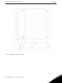
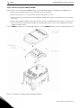
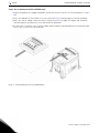
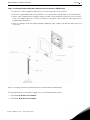
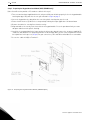
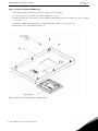
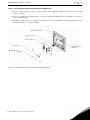
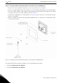
Keypad Remote Control Options
Installation Manual
DPD00109
Need Help?
This manual answers most installation and startup questions
that may arise. However, if you have any problems,
please let your first call be to us.
Vacon, Inc.
Chambersburg, PA 17202
Normal business hours:
(North America)
8:00 AM to 5:00 PM, Eastern time
+1 877-Vacon06
(+1 877-822-6606)
After-hours support is also available
and Vacon, Inc. are trademarks of Vacon Plc, a member of Vacon Group.
All other product names are trademarks of their respective companies.
Copyright 2008, Vacon, Incorporated. All rights reserved.
Keypad Remote Control Options
vacon
3
Installing Keypad Remote Control Options
Introduction
Remote control options allow the keypad functionality of the X4 and X5 AC drives to be used remotely from the
controller itself. The options provide a NEMA 4X / IP66 rating for the keypad in a remote location. Products covered
by this instruction manual include XRKPM, XRKWM, and XRKMK.
The XRKPM is used with X4 or X5 drives of sizes 0, 1, and 2, when the drive is panel mounted and there is no need
for the controller to maintain its designed NEMA 4X / IP66 rating.
The XRKWM is used with X4 or X5 drives of sizes 0, 1, and 2, when the drive is wall-mounted and it is imperative that
the controller’s normal enclosure rating be maintained.
The XRKMK is used with size 3, 4, and 5 drives, and allows the keypad to be mounted in a NEMA 4X / IP66 enclosure,
while allowing the drive to maintain its designed rating (sizes 3 and 4 are NEMA 4X / IP66; size 5 is NEMA 12/IP55).
This manual is organized so that each of the products can be installed by following the steps outlined below:
XRKPM (panel-mounted)
Follow Steps 1, 2, 3, 4, 5
XRKWM (wall-mounted)
Follow Steps 1, 2, 6, 7, 8
XRKMK (enclosure-mounted)
Follow Steps 1, 9, 10, 11, 12
Option Kit Contents
The option kits include the following materials:
XRKPM
XRKWM
XRKMK
Keypad module housing (2)1
Keypad interface board
Keypad interface board
Keypad interface board
Keypad interface assembly
Remote keypad assembly
Remote keypad assembly
Connector stacker
Overlay
Overlay
Loop clamps
Ribbon cable (12 feet)
Wire tie (5)
Wire tie (4)
Ribbon cable clamps (4)
Wire tie base (4)
Keypad module housing (2)
1
2
Screw: M2.5x6 (3)
3
Screws: M5x12 (4)
NOTES:
1.
2.
3.
Screw: M2.5x6 (3)
Wire tie base (4)
2
Screw: M3.5x10 (5)2
3
Screws: M5x12 (4)3
Screws: M5x12 (4)
Only one will be used.
To mount the keypad interface board into the proper keypad interface housing
To mount the remote keypad assembly into the host enclosure
For the XRKWM and the XRKMK, customers must supply shielded cable. Belden #22418 or the equivalent is
suggested. Fifteen circuits are required, but may be accomplished with multiple strands of cable, each with fewer
conductors. This cable should not exceed 100 feet in length.
Email: [email protected] • Fax 717-264-3115
4
vacon
Keypad Remote Control Options
!
WARNING
SENSITIVE EQUIPMENT
The keypad contains static-sensitive components. It should be handled only by a static-safe installer,
using a grounded wrist strap.
Failure to observe this precaution may cause premature equipment failure.
!
DANGER
HAZARDOUS VOLTAGE
• Disconnect all power before servicing a drive unit or its components. WAIT 5 MINUTES until the DC
bus capacitors discharge.
• Ensure that any other power sources that may feed control logic have been disconnected.
• DO NOT short across DC bus capacitors or touch unshielded components or terminal strip screw
connections with voltage present.
• Install all covers before applying power or starting and stopping the drive.
• The user is responsible for conforming to all applicable code requirements with respect to grounding
all equipment.
• Many parts in this drive, including printed circuit boards, operate at line voltage. DO NOT TOUCH.
Use only electrically-insulated tools.
Before servicing any drive.
• Disconnect all power.
• Place a “DO NOT TURN ON” label on the drive disconnect.
• Lock the disconnect in the open position.
Failure to observe these precautions will cause shock or burn, resulting in severe personal
injury or death.
Step 1. Preparing the Host Enclosure (XRKPM, XRKWM, and XRKMK)
Figure 1 on page 5 is a layout for remote keypad assembly mounting.
If you are fabricating a simple remote control station with this option, the following standard enclosure suggestions
are recommended: Hoffman #A1008CHNF or Hammond #1414N4PHI.
24-hour support 1-877-822-6606
Keypad Remote Control Options
Figure 1: Dimensions of Remote Keypad Kit
Email: [email protected] • Fax 717-264-3115
vacon
5
6
vacon
Keypad Remote Control Options
Step 2. AC Drive Preparation (XRKPM, XRKWM)
Note: For drive sizes 3 and larger (XRKMK), skip to step 9, beginning on page 13, and proceed through Step 12.
1. Note the warnings and cautions on the unit and in the user’s manual.
2. Loosen the four (4) cover screws from the AC drive and remove the cover.
3. Remove the two (2) screws that secure the keypad assembly and retain these for future use. These are M4 x
10 screws.
4. Remove the keypad assembly. It will not be used in the final assembly, but may be useful as a replacement
part in another unit. If you will be storing it for a long period of time, re-use the static bag that the remote
keypad assembly came in.
For the XRKPM, perform steps 3-5, beginning on page 7. For the XRKWM, perform steps 6-8, beginning on page 10.
Figure 2: Removing the Keypad Assembly (XRKPM and XRKWM)
24-hour support 1-877-822-6606
Keypad Remote Control Options
vacon
7
Step 3. Preparing the Keypad Interface Module (KIM) (XRKPM only)
1. There are two housings supplied with the kit; only one will fit your AC drive properly. Select the keypad
module housing that physically matches the one you removed in Step 2.
2. Insert the keypad interface board into the rear of the plastic housing that you selected.
3. Fasten it with the three (3) M2.5 x 6 screws provided, limiting the torque applied to 6 in-lb maximum.
4. Remove the adhesive covering liner from the overlay.
5. Align and adhere the overlay to the front side of the keypad module. Press the part down firmly to ensure
adequate adhesion to the plastic housing.
6. Fasten a cable clamp to the outside of the overlay. (Positioning aids are visible on the surface.)
7. Connect the ribbon cable to the interface board through the opening in the overlay. To provide strain relief,
route the cable through the cable clamp that you just installed.
Figure 3: Preparing the Keypad Interface Module (XRKPM Option)
Email: [email protected] • Fax 717-264-3115
8
vacon
Keypad Remote Control Options
Step 4. Re-assembling the AC Drive (XRKPM only)
1. Plug the Keypad Interface Module (KIM) fabricated in Step 3 into the inverter, as it was originally (see Step 2,
#4).
2. Fasten the KIM with the two (2) M4 x 10 screws removed in Step 2, limiting torque to 12 in-lb. maximum.
3. Make sure that all cabling is routed so that it is not pinched in the assembly. The ribbon cable should be
routed through the opening in the cover and should exit downward.
4. If or when you re-install the cover, route the ribbon cable through the opening and limit the installation torque
on the cover screws to 26 in-lb. maximum.
Figure 4: Re-assembling the AC Drive (XRKPM Option)
24-hour support 1-877-822-6606
Keypad Remote Control Options
vacon
9
Step 5. Installing the Remote Keypad Assembly into the Host Enclosure (XRKPM only)
1. Position the remote keypad assembly into the enclosure prepared in Step 1 (page 4).
2. Fasten the keypad module with the four (4) M5 x 12 screws provided, limiting torque to 26 in-lb maximum.
3. Install a cable clamp below the keypad assembly as shown in the drawing, fastening it to the host enclosure.
Connect the ribbon cable to the J1 connector and route it through the cable clamp. The cable should exit the
keypad module downward.
4. Route the cabling as needed to avoid any damage. Additional cable clamps are provided to allow strain relief
for the wire.
Figure 5: Installing the Remote Keypad Assembly into the Host Enclosure (XRKPM Option)
For detailed information on using the keypad, refer to the following documentation:
•
DPD 00088, X4 AC Drive User’s Manual
•
DPD 00089, X5 AC Drive User’s Manual
Email: [email protected] • Fax 717-264-3115
10
vacon
Keypad Remote Control Options
Step 6. Preparing the Keypad Interface Module (KIM) (XRKWM only)
(Note: You will need to provide a 15-conductor cable for this step.)
1. There are two housings supplied with the kit; only one will fit your AC drive properly. Select the keypad module
housing that physically matches the one you removed in Step 2 on page 6.
2. Insert the keypad interface board into the rear of the plastic housing that you selected.
3. Fasten it with the three (3) M2.5 x 6 screws provided, limiting the torque applied to 6 in-lb maximum.
4. Remove the adhesive covering liner from the overlay.
5. Align and adhere the overlay to the front side of the keypad module. Press the part down firmly to ensure
adequate adhesion to the plastic housing.
6. Install the tie wrap provided in the lower portion of the interface board. Connect the customer-supplied 15conductor cable within the tie wrap and terminate to TB1 and TB2. Note the wire color assignments: this will
be helpful later in this process (Step 8). For your convenience, TB1 and TB2 terminal blocks are removable.
7. Secure the cable shield(s) to Terminal 1.
Figure 6: Preparing the Keypad Interface Module (XRKWM Option)
24-hour support 1-877-822-6606
Keypad Remote Control Options
vacon
11
Step 7. Re-assembling the AC Drive (XRKWM only)
1. Plug the Keypad Interface Module (KIM) fabricated in the previous step into the inverter, as it was originally
(see Step 2, #4).
2. Fasten the KIM with the two (2) M4 x 10 screws removed in Step 2, limiting torque to 12 in-lb. maximum.
3. Make sure that all cabling is routed so that it is not pinched in the assembly. The multi-conductor must be
routed through an unused conduit entry. Be sure to use the appropriate conduit fittings for your environment.
4. When you re-install the cover (required for NEMA 4X / IP66 integrity), limit the installation torque on the four
(4) screws to 26 in-lb. maximum.
Figure 7: Re-assembling the AC Drive (XRKWM Option)
Email: [email protected] • Fax 717-264-3115
12
vacon
Keypad Remote Control Options
Step 8. Installing the Remote Keypad Assembly into the Host Enclosure (XRKWM only)
1. Position the remote keypad assembly into the enclosure prepared in Step 1 (page 4).
2. Fasten the keypad module with the four (4) M5 x 12 screws provided, limiting torque to 26 in-lb maximum.
3. Secure the multi-conductor cable using the loop clamp on the lower portion of the keypad interface board.
You may need to loosen the cable clamp to install the cable in it.
4. Terminate the individual wires to TB1 and TB2 as in Step 6, #6. For your convenience, TB1 and TB2 terminal
blocks are removable.
5. Route the cabling as needed to avoid any damage. Additional wire ties and tie bases are provided to allow
strain relief for the wire.
Figure 8: Installing the Remote Keypad Assembly into the Host Enclosure (XRKWM Option)
For detailed information on using the keypad, refer to the following documentation:
•
DPD 00088, X4 AC Drive User’s Manual
•
DPD 00089, X5 AC Drive User’s Manual
24-hour support 1-877-822-6606
Keypad Remote Control Options
vacon
13
Step 9. AC Drive Preparation (XRKMK only)
1. Note the warnings and cautions on the unit and in the user’s manual.
2. Loosen the cover screws from the AC drive and open the cover.
3. Remove the four (4) screws that secure the keypad assembly and retain these for future use. These are M5 x
12 screws.
4. Unplug the ribbon cable and remove the keypad assembly. It will be re-used in Step 12.
5. Now go on to Step 10, beginning on page 14.
Figure 9: Removing the Keypad Assembly (XRKMK Option)
Email: [email protected] • Fax 717-264-3115
14
vacon
Keypad Remote Control Options
Step 10. Installing the Keypad Interface Module (KIM) into the AC Drive (XRKMK only)
1. Position the keypad interface module (KIM) into the door opening.
2. Fasten the keypad module with the four (4) M5 x 12 screws provided, limiting torque to 26 in-lb maximum.
3. Reconnect the ribbon cable to the connector socket and ensure it is still retained by the cable clamp on the
door.
4. Secure the multi-conductor cable using the loop clamp on the lower portion of the keypad interface board.
You may need to loosen the cable clamp to install the cable in it.
5. Terminate the individual wires to TB1 and TB2 as in Step 6, #6. Note the wire color assignments; this will be
useful in Step 12. For your convenience, TB1 and TB2 terminal blocks are removable.
6. Secure the cable shield(s) to Terminal 1.
7. Route the cabling as needed to avoid any damage. The multi-conductor must be routed through an unused
conduit entry. Be sure to use appropriate conduit fittings for your environment. Additional wire ties and tie
bases are provided to allow strain relief for the wire.
8. As you fasten the enclosure, limit the installation torque to 26 in-lb. maximum.
Figure 10: Installing the KIM into the AC Drive (XRKMK Option)
24-hour support 1-877-822-6606
Keypad Remote Control Options
vacon
15
Step 11. Assembling the Remote Keypad Interface (XRKMK only)
1. Insert the connector stacker into the receptacle on the remote keypad assembly (removed in Step 9) as shown
in Figure 11 below.
2. Insert the keypad interface board onto the rear of the keypad assembly, being sure to engage the connector
stacker simultaneously.
3. Fasten the keypad interface assembly with five (5) M3.5 x 10 screws along with the loop clamp provided. Limit
installation torque to 12 in-lb. maximum.
Figure 11: Assembling the Remote Keypad Interface (XRKMK Option)
Email: [email protected] • Fax 717-264-3115
16
vacon
Keypad Remote Control Options
Step 12. Installing the Remote Keypad Assembly into the Host Enclosure (XRKMK only)
1. Position the remote keypad assembly into the enclosure prepared in Step 1 (page 4).
2. Fasten the keypad module with the four (4) M5 x 12 screws provided, limiting torque to 26 in-lb maximum.
3. Secure the multi-conductor cable using the loop clamp on the lower portion of the keypad interface board.
You may need to loosen the cable clamp to install the cable in it.
4. Terminate the individual wires to TB1 and TB2 as in Step 10. For your convenience, TB1 and TB2 terminal
blocks are removable.
5. Route the cabling as needed to avoid any damage. Additional wire ties and tie bases are provided to allow
strain relief for the wire.
Figure 12: Installing the Remote Keypad Assembly into the Host Enclosure (XRKMK Option)
For detailed information on using the keypad, refer to the following documentation:
•
DPD 00088, X4 AC Drive User’s Manual
•
DPD 00089, X5 AC Drive User’s Manual
24-hour support 1-877-822-6606
NOTES
head office and production:
Vaasa
Vacon Plc
Runsorintie 7
65380 Vaasa
[email protected]
telephone: +358 (0)201 2121
fax: +358 (0)201 212 205
production:
Suzhou, China
Vacon Suzhou Drives Co. Ltd.
Building 11A
428# Xinglong Street, SIP
Suchun Industrial Square
Suzhou 215126
telephone: + 86 512 62836630
fax: + 86 512 62836618
Naturno, Italy
Vacon S.R.I
Via Zone Industriale, 11
39025 Naturno
production:
Chambersburg, USA
3181 Black Gap Road
Chambersburg, PA 17202
TB Wood's (India) Pvt. Ltd.
#27, 'E' Electronics City
Hosur Road
Bangalore - 560 100
India
Tel. +91-80-30280123
Fax. +91-80-30280124
sales companies and representative offices:
finland
Helsinki
Vacon Plc
Äyritie 8
01510 Vantaa
telephone: +358 (0)201 212 600
fax: +358 (0)201 212 699
Tampere
Vacon Plc
Vehnämyllynkatu 18
33580 Tampere
telephone: +358 (0)201 2121
fax: +358 (0)201 212 750
australia
Vacon Pacific Pty Ltd
5/66-74, Micro Circuit
Dandenong South, VIC 3175
telephone: +61 (0)3 9238 9300
fax: +61 (0)3 92389310
austria
Vacon AT Antriebssysteme GmbH
Aumühlweg 21
2544 Leobersdorf
telephone: +43 2256 651 66
fax: +43 2256 651 66 66
belgium
Vacon Benelux NV/SA
Interleuvenlaan 62
3001 Heverlee (Leuven)
telephone: +32 (0)16 394 825
fax: +32 (0)16 394 827
brazil
Vacon Brazil
Alameda Mamoré, 535
Alphaville - Barueri -SP
Tel. +55 11 4166-5707
Fax. +55 11 4166-5567
canada
Vacon Canada
221 Griffith Road
Stratford, Ontario N5A 6T3
telephone: +1 (519) 508-2323
fax: +1 (519) 508-2324
china
Vacon Suzhou Drives Co. Ltd.
Beijing Branch
A528, Grand Pacific Garden Mansion
8A Guanghua Road
Beijing 100026
telephone: + 86 10 51280006
fax: +86 10 65813733
czech republic
Vacon s.r.o.
Kodanska 1441/46
110 00 Prague 10
telephone: +420 234 063 250
fax: +420 234 063 251
france
Vacon France
ZAC du Fresne
1 Rue Jacquard - BP72
91280 Saint Pierre du Perray CDIS
telephone: +33 (0)1 69 89 60 30
fax: +33 (0)1 69 89 60 40
germany
Vacon GmbH
Gladbecker Strasse 425
45329 Essen
telephone: +49 (0)201 806 700
fax: +49 (0)201 806 7099
slovakia
Vacon s.r.o. (Branch)
Seberiniho 1
821 03 Bratislava
Tel. +421 243 330 202
Fax. +421 243 634 389
Vacon OEM Business Center GmbH
Industriestr. 13
51709 - Marienheide
Germany
Tel. +49 02264 17-17
Fax. +49 02264 17-126
spain
Vacon Drives Ibérica S.A.
Miquel Servet, 2. P.I. Bufalvent
08243 Manresa
telephone: +34 93 877 45 06
fax: +34 93 877 00 09
india
Vacon Drives & Control Plc
Plot No 352
Kapaleeshwar Nagar
East Coast Road
Neelangarai
Chennai-600041
Tel. +91 44 244 900 24/25
sweden
Vacon AB
Anderstorpsvägen 16
171 54 Solna
telephone: +46 (0)8 293 055
fax: +46 (0)8 290 755
italy
Vacon S.p.A.
Via F.lli Guerra, 35
42100 Reggio Emilia
telephone: +39 0522 276811
fax: +39 0522 276890
the netherlands
Vacon Benelux BV
Weide 40
4206 CJ Gorinchem
telephone: +31 (0)183 642 970
fax: +31 (0)183 642 971
norway
Vacon AS
Bentsrudveien 17
3080 Holmestrand
telephone: +47 330 96120
fax: +47 330 96130
romania
Vacon Romania - Reprezentanta
Cuza Voda 1
400107 Cluj Napoca
Tel. +40 364 118 981
Fax. +40 364 118 981
russia
ZAO Vacon Drives
Ul. Letchika Babushkina 1,
Stroenie 3
129344 Moscow
telephone: +7 (495) 363 19 85
fax: +7 (495) 363 19 86
ZAO Vacon Drives
2ya Sovetskaya 7, office 210A
191036 St. Petersburg
telephone: +7 (812) 332 1114
fax: +7 (812) 279 9053
thailand
Vacon South East Asia
335/32 5th-6th floor
Srinakarin Road, Prawet
Bangkok 10250
Tel. +66 (0)2366 0768
ukraine
Vacon Drives Ukraine (Branch)
42-44 Shovkovychna Str.
Regus City Horizon Tower
Kiev 01601, Ukraine
Tel. +380 44 459 0579
Fax +380 44 490 1200
united arab emirates
Vacon Middle East and Africa
Block A, Office 4A 226
P.O.Box 54763
Dubai Airport Free Zone
Dubai
Tel. +971 (0)4 204 5200
Fax: +971 (0)4 204 5203
united kingdom
Vacon Drives (UK) Ltd.
18, Maizefield
Hinckley Fields Industrial Estate
Hinckley
LE10 1YF Leicestershire
telephone: +44 (0)1455 611 515
fax: +44 (0)1455 611 517
united states
Vacon, Inc.
3181, Black Gap Road
Chambersburg, PA 17202
telephone: +1 (877) 822-6606
fax: +1 (717) 267-0140