1
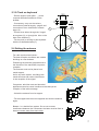
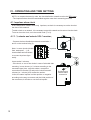
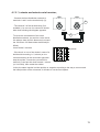
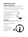
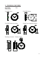
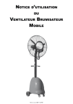
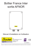
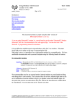
Clock
Profil 960
For indoor or outdoor models
INSTALLATION AND OPERATING INSTRUCTIONS
B.P. 1
49340 TRÉMENTINES
FRANCE
Tél. : 02 41 71 72 00
Fax : 02 41 71 72 01
www.bodet.com
Réf. : 605775 K
When receiving goods please chek nothing is broken otherwise make a claim near shipping company.
Table of contents
I - INITIAL VERIFICATION . . . . . . . . . . . . . . . . . . . . . . 3
1.1 Unpacking the clock . . . . . . . . . . . . . . . . . . . . . . . . . . . . . . . 3
1.2 Cleaning . . . . . . . . . . . . . . . . . . . . . . . . . . . . . . . . . . . . . 4
II - INSTALLATION . . . . . . . . . . . . . . . . . . . . . . . . . . 4
2.1 Single face indoor clock . . . . . .
2.2 Single Face outdoor clock . . . . .
2.3 Double Face clock . . . . . . . . .
2.3.1. Double Face integrated clock
2.3.2 Clock on keyboard . . . . . .
2.4 Setting the antenna . . . . . . . . .
.
.
.
.
.
.
.
.
.
.
.
.
.
.
.
.
.
.
.
.
.
.
.
.
.
.
.
.
.
.
.
.
.
.
.
.
.
.
.
.
.
.
.
.
.
.
.
.
.
.
.
.
.
.
.
.
.
.
.
.
.
.
.
.
.
.
.
.
.
.
.
.
.
.
.
.
.
.
.
.
.
.
.
.
.
.
.
.
.
.
.
.
.
.
.
.
.
.
.
.
.
.
.
.
.
.
.
.
.
.
.
.
.
.
.
.
.
.
.
.
.
.
.
.
.
.
.
.
.
.
.
.
.
.
.
.
.
.
4
5
5
6
7
7
III - POWER SUPPLY . . . . . . . . . . . . . . . . . . . . . . . . . 8
3.1. AFNOR HM clock 230V : . . . . . . . . . . . . . . . . . . . . .
3.2. DHF HM 230V clock : . . . . . . . . . . . . . . . . . . . . . . .
3.3. AFNOR HM clock low voltage 6/24V . . . . . . . . . . . . . . .
3.4. France Inter servo second clock : . . . . . . . . . . . . . . . . .
3.5. Independent Quartz clock on mains : . . . . . . . . . . . . . . .
3.6. Minute, ½ minute, with synchronous second hand clock receiver .
3.7. Lighting connection . . . . . . . . . . . . . . . . . . . . . . . .
.
.
.
.
.
.
.
.
.
.
.
.
.
.
.
.
.
.
.
.
.
.
.
.
.
.
.
.
.
.
.
.
.
.
.
.
.
.
.
.
.
.
.
.
.
.
.
.
.
8
8
9
9
10
10
11
IV - OPERATING AND TIME SETTING. . . . . . . . . . . . . . . . 12
4.1. Impulses slave clock . . . . . . . . . . . . . . . . . .
4.1.1. ½ minute and minute 24V // receiver, . . . . . .
4.1.2. ½ minute and minute serial receiver, . . . . . .
4.2. AFNOR/IRIG-B time signal reception . . . . . . . . .
4.2.1. Time signal reception HM 230V (Hour - Minute)
4.2.2. Time signal reception TBT 6/24V . . . . . . . .
4.3. France Inter radio receiver clock . . . . . . . . . . .
4.4. DHF clock . . . . . . . . . . . . . . . . . . . . . . .
4.5. Independent Quartz on mains with remote keyboard .
.
.
.
.
.
.
.
.
.
.
.
.
.
.
.
.
.
.
.
.
.
.
.
.
.
.
.
.
.
.
.
.
.
.
.
.
.
.
.
.
.
.
.
.
.
.
.
.
.
.
.
.
.
.
.
.
.
.
.
.
.
.
.
.
.
.
.
.
.
.
.
.
.
.
.
.
.
.
.
.
.
.
.
.
.
.
.
.
.
.
.
.
.
.
.
.
.
.
.
.
.
.
.
.
.
.
.
.
.
.
.
.
.
.
.
.
.
12
12
13
14
14
14
15
15
16
V - TECHNICAL FEATURES . . . . . . . . . . . . . . . . . . . . . 17
VI - WHAT TO DO IF...?
2
...CHECK.. . . . . . . . . . . . . . . . . 20
ENGLISH
I - INITIAL VERIFICATION
Thank you for choosing a BODET clock. This product has been carefully designed for your
satisfaction based on ISO9001 quality requirements. We advise you to read this manual
thoroughly before attempting to manipulate the clock.
Keep this booklet during all the life of your clock, so that you can refer to it each time it is
necessary.
Bodet accepts no responsibility for accidents resulting from any use not conforming
with the above provisions.
Any modification to the product will invalidate the warrantee.
1.1 Unpacking the clock
Unpack with caution and check the contents of the packaging. It must contain :
- the Profil clock,
- for radio synchronised models : the antenna,
- for outdoor models : a key to open the casing,
- an antistatic cleaning kit,
- this booklet.
Versions : a label inside the clock specifies what model the clock is :
AFNOR HM 230v = the clock is a receiver driven by a master clock that sends
AFNOR NFS-87500A time coded messages ; it is powered by 240 VAC.
AFNOR HM TBT = the clock is a receiver driven by a master clock that sends AFNOR
NFS-87500A time coded messages ; it is supplied in low voltage 6 / 24 V AC or DC.
AF/FI HM = the clock is a receiver driven by : a master clock that sends AFNOR
NFS-87500A coded time messages or a radio France Inter receiver antenna, and
powered by 240 VAC.
1/2 MN 24V = the clock is a receiver driven by a master clock that sends 1/2 minute
impulses on a parallel line.
MN 24V = the clock is a receiver driven by a master clock that sends minute impulses
on a parallel line.
24V + SEC = the clock is a receiver driven by a master clock that sends minute impulses
on a parallel ligne ; it is powered by 240 VAC, with a servo second hand.
1/2MN SER = the clock is a receiver driven by a master clock that sends ½ minute
impulses on a serial line.
1/2MN SEC = the clock is a receiver driven by a master clock that sends ½ minute
3
impulses on a serial ligne ; it is powered by 240 VAC, with a servo second hand.
REC MN 1V5 = the clock is a receiver driven by a control unit “Remote keyboard” or
radio synchronised control unit “BT radio” that sends minute impulses.
RAD DHF = the clock is radio-synchronised by a DHF transmitter and battery supplied.
DHF HM 230V = the clock is radio-synchronised by a DHF transmitter; it is supplied in
240VAC.
1.2 Cleaning
Use an antistatic product of similar type to the one shipped in the original packaging. Never
use alcohol, acetone or any other solvent liable to damage the casing and glass on your
clock.
II - INSTALLATION
Select the place where the clock will be installed while making sure that radio reception is
correct for radio synchronisation models.
The radio receiver clock should be installed in a place that is free from electrical interference
(cathode tube, transformers, etc.).
Avoid fixing the clock directly to a metal plate or reinforced concrete wall.
The clock orientation (dial perpendicular to the emitter direction) towards the emitter
enhances the reception.
The best reception conditions are outside buildings or near by a window.
2.1 Single face indoor clock
3
572
- Drill the support to the required
dimensions.
- Place the 2 screws Ø6 (1) with their
washers.
- If necessary, carry out the various
connections (external supply : see
page 8 and connection to a time
distribution network : see page 12).
- Hang the clock and screw it with a
size 10 flat key.
3
2
1
1
8
4
2.2 Single Face outdoor clock
1
11
2
9
4
8
4
3
7
5
6
5
3
4
2
6
2
1
7
1
9
3
8
12
10
N
- Carry out the various connections (external
supply : see page 8 and connection to time
distribution network : see page 12).
12
L
- Hang the clock and fix it with M8 screws
(4), without locking it, after you have put the
wires (between Ø7 and Ø10) through the
waterproof pressure joints (5).
11
10
Ø 440 mm
- Open the clock by giving the 2 screws (3) a
quarter turn with the key (1), and then pull the
whole dial towards you (hinge arm opening).
The hinge arm opening system ensures a fast
and secure maintenance of the lighting without
having to put the front part of the clock on the
ground.
1
- Lock the clock.
- Power it.
- Reset the time if necessary.
- Close the clock.
5
2.3 Double Face clock
2 models of double face clocks are available :
- One model with an integrated bracket that includes two back to back dials.
- One model with a hinged arm system that holds two single face clocks.
5
2.3.1. Double Face integrated clock
150
70
Drill the support (wall, pillar, ...) to the
required dimensions and fix the bracket.
Ø9
- Unscrew by 10 mm the 2 bolts (B) on
each face.
B
- Remove each face by rotating them
anticlockwise (for receiver clocks, Do
Not forget to disconnect the 2
movements).
6
7
- Fix the double sided bracket after you
have put the wires either through the
plate support (6), or through the aperture
on the side of the bracket (7).
B
- Carry out the various connections
(external supply : page 8 and time distribution
network : page 12).
- Power the clock and reset the time if
necessary.
- Place each face on the bracket and rotate
them clockwise to place the clock in its final
position.
- Screw the bolts (B) to lock the clocks in
rotation.
6
B
L
Ecl
N
230V
0.5
2.3.2 Clock on keyboard
150
70
- Drill the support (wall, pillar, ...) to the
required dimensions and then fix the
bracket.
- If necessary, carry out the various
connections (external supply : page 8 and
connection to time distribution network :
page 12).
- Put the wires either through the hinged
arm system (6), or through the hole on the
side of the bracket (7).
- Fix the clock (or clocks) to this keyboard
with the 2 threaded shafts (C).
7
Ø9
6
C
2.4 Setting the antenna
For radio synchronised clocks :
The best reception conditions are outside
buildings or near windows.
Positioning the antenna (perpendicular to
the direction of the transmitter) improves
reception.
The antenna must not be placed on a
metal support.
As for any radio system, a building with
metal structures can cause interference
in the reception of the signal.
Computers, television sets and electrical
appliances can also cause interference that disrupt the
reception of the radio message.
- Unlock the antenna from its support.
- Fix the support with the screw supplied and lock the antenna
again.
Beware : in a double face system. So as not to cause
interference between the 2 antennas, the latter must be fixed at
least one metre away from each other.
7
III - POWER SUPPLY
Installation and maintenance of this equipment must be carried out by qualified personnel
only.
Electrical installation must comply with current standard CEI 364. (NF C15-100 in France for
example).
The mains supply for the clocks must include a neutral phase circuit breaker 10A C curb,
rapidly accessible. This circuit breaker must be switched off during maintenance operations.
Note : the power supply wires must be linked near their fixing point.
3.1. AFNOR HM
clock 230V :
N
!
N
230V
L
F
STOP
Permanent power
supply 230V
- Connect mains supply 230 Volt 50 Hz to the
power terminal: max.1.5 mm2 wire and stripped
over 5 mm.
- Lock the wires with collars.
Permanent power
supply 230V
N
230V
L
2
3.2. DHF HM 230V clock :
Ecl
0.5A
1 2
N
L
This card is protected by 1 fuse
(F) 0,2AT 250V.
8
Ecl
0.5A
START
!
- Lock the wires with collars.
L
- Connect mains supply 230 Volt
50 Hz to the supply card terminal :
max.1,5 mm2 wire and bare
6
on 5 mm.
3.3. AFNOR HM clock low voltage 6/24V
Connect the low voltage (TBT) power supply (6 to 24V AC or DC) to the connectors 1 and 2:
maximum 1,5 mm2 wire section (5mm bare).
It is compulsory, for a correct running, to respect the following parameters.
These parameters are calculated considering 8/10 mm wire section with 1A (Microquartz
Delta).
Distance
100 m
200 m
300 m
400 m
500 m
600 m
1 km
2
3
4
1
2
3
4
1
10
20
30
40
50
Distance in m
24VDC
15VDC
8300
3200
830
320
415
160
275
105
208
75
165
45
1
Number of
clocks
Number of clocks
24VDC
15VDC
71
32
41
16
27
10
20
6
16
6
13
5
8
3
3.4. France Inter servo second clock :
- Connect mains supply 230 Volt
50 Hz to the supply card terminal :
max. 1,5 mm2 and bare on 5 mm.
The earth wire must be longer than
those of live and neutral.
7
This card is protected by 2 fuses
(F) 2A 250V.
- Connect the terminal (7) of the
battery, on this main card.
L
0
230
F
1
2
3
- Lock the wires with collars.
N
Permanent power
supply 230V
9
3.5. Independent Quartz clock on mains :
Single Face.
– Connect mains supply (230VAC) to the terminal (20) of the
power supply unit (ref.933006).
20
22
– Connect the impulses line between the terminal (22) of the
power supply unit and the terminal (2) of the clock.
The time base is protected by a 0,2AT / 250V fuse (21).
21
23
Double Face.
– Connect mains supply (230VAC) to the
terminal (20) of the power supply unit.
– Connect the impulses ligne between the
terminal (22) of the power supply unit
and the terminal (2) of the clock.
N
L
N
1
2
1
2
2
Impulses
L
– Check that the dip switch (23), on the
card of the time setting box, is in “DF”
position.
3.6. Minute, ½ minute, with
synchronous second hand clock receiver
2
L
N
Connect permanent power supply 230V +earth on
the terminal (4).
24V // receiver + second hand
Impulses
Permanent power
supply 230V +earth
1
– The second hand is driven by an independent
motor. This motor must be permanently supply.
N
4
½ minute serial receiver + second hand
L
N
L
N
1
2
- Nota : the power supply wires should be
assembled together near their connecting
terminal.
Lighting
230V + earth
L
The earth wire must be longer than the other
ones.
10
Impulses
Permanent power
supply 230V +
earth
Lighting
230V + earth
3.7. Lighting connection
A 10 A fuse or circuit breaker for the
lighting power supply should be
installed and switched off prior to any
maintenance in the clock.
N
L
Lighting
230V + earth
N
1
1
2
2
2
L
– Connect lighting supply 230V + earth
(0,55A) on the terminal (2), the earth
wire must be longer than the other
ones.
– Nota : the power supply wires should be
assembled together near their connecting terminal.
11
IV - OPERATING AND TIME SETTING
NOTA : to respect the security rules, the time distribution network must be be SELV-type.
- The impulses wires should be assembled together near their connecting terminal.
4.1. Impulses slave clock
A time distribution network emits only impulses, so that it is necessary to set the clock at
the time of this network.
To add a clock on a network, it is necessary to stop this network and to set on time the clock.
To set on time the clock, turn the control knob (7 or 8).
4.1.1. ½ minute and minute 24V // receiver,
7
2
- Connect the time distribution network to terminals 1
and 2 on the terminal strip (3).
1
Impulses
Leave works 2 minutes.
- If the clock, or one of the clocks in case of a double side
mounting, is one minute (or ½ minute according to the
movement type) late : stop the emitter, reverse the
connection on terminal (3) and put the clock forward 2
minutes (or 1 minute), then restart the emitter.
In fact, the same impulse is either positive or negative
according to the way to connect and the initial position of
the movement, it will take or not the first impulse.
12
2
1
N
3
L
Nota : in some clocks (double
face, waterproof, ...), an
intermediate terminal allows
to connect impulses ligne
easily.
3
8
Synchronous
second hand
movement
4.1.2. ½ minute and minute serial receiver,
- Connect the time distribution network to
terminals 1 and 2 on the terminal strip (3).
2
1
3
2
1
3
Impulses
1
To insure the continuation of the serial
distribution network, (to avoid to cut the serial
line when a slave clock is disconnect) connect
the 100 Ohms 1/2 Watt resistor delivered (for
65mA).
Leave works 2 minutes.
3
2
- The terminal 3 of the terminal strip (3) is
available. You can use it to connect a double
side clock following the diagram opposite.
8
L
N
- If the clock, or one of the clocks in case of a
double side mounting, is ½ minute (or one
minute according to the movement type) late :
stop the emitter, reverse the connection on
terminal (3) and put the clock forward 1 minute
(or 2 minutes), then restart the emitter.
In fact, the same impulse is either positive or negative according to the way to connect and
the initial position of the movement, it will take or not the first impulse.
13
4.2. AFNOR/IRIG-B time signal reception
Operating principle of AFNOR HM receiver clock :
During 1 hour without reception of the time signal the clock operates with its own time basis.
If the signal recovery is achieved within this hour, the clock will be resynchronised
automatically. After 1 hour the clock is reset and hands are set on position 12.00.
- When switching on power supply, hands are set at 12.00 until the correct reception of the
time signal is achieved. After 3 successive coherent AFNOR time signals are received, the
clock starts and automatically get on time with fast impulses.
4.2.1. Time signal reception HM 230V (Hour - Minute)
- Connect the time signal network to the
upper terminals of the AFNOR receiver card.
Caution: to avoid interferences due to high
voltage lighting, the wire between the cable
gland and the terminal must be as short as
possible.
- Check that the dip switch (6), on the
AFNOR impulse card, is pushed toward left of
the PCB (start position).
6
START
STOP
N
L
AFNOR input
Operating with battery :
- Without power supply 230V the clock operates with its battery during 1 hour.
- After 1 hour without time signal reception or if the battery voltage drops down, hands are
set position 12.00 until power supply recovery.
4.2.2. Time signal reception TBT 6/24V
- Connect the afnor line on
connectors 3 and 4.
2
3
4
1
2
3
4
14
1
- When receiving the power, the
hands are driven to 12h00 until the
clock receives a radio signal. After
controlling the data (3 coherent
messages) the clock is automatically
driven to the current time by
accelerated impulses.
4.3. France Inter radio receiver clock
Antenna connection :
Connect the 2 wires of the antenna on the FI and
GND terminal.
Caution: to avoid interferences due to high voltage
lighting, the wire between the cable gland and the
terminal must be as short as possible.
16
17
15
Check that the dip switch (15) is in France-Inter
receiver position, push toward the down of the
PCB.
When switching on power supply, hands are set at
12.00 until the correct reception of the time signal is achieved or a manual setting on time is
done.
After 3 successive coherent France-Inter time signals are received, the clock starts and
automatically get on time with fast impulses.
Manual time setting :
– At the first press on button “time setting” (17) , the internal clock starts.
– Every press on button “time setting” (17) advances the clock by one minute.
– After this manual time setting, the clock operates in stand alone mode until reception of the
signal, or reset function by pressing button (16) or a power supply failure.
Operating principle of France Inter receiver :
– Once the clock is synchronised, it will operates with its own time basis even if there is no
more reception until there is no power failure.
Operating with battery :
– Without power supply 230V the clock operates with its battery during 1 hour.
– After 1 hour without time signal reception or if the battery voltage drops down, hands are set
position 12.00 until power supply recovery.
– The synchronous second hand witch is powered by the main 12V 50Hz, will stop
immediately.
4.4. DHF clock
Ensure that the transmitter is set in “Init” mode. Switch the clock power on (for models with
batteries, insert the batteries matching the polarities), the hands will move forward by 2
minutes. The clock will try to pick up the radio signal. If the reception is good, the clock is
synchronised automatically. If the reception is bad, increase the transmission power or
install a DHF repeater.
15
4.5. Independent Quartz on mains with remote keyboard
See the booklet of the remote keyboard, reference : 605198.
Attention : in case of a double face clock, check that the Dip switch (6) of the remote
keyboard is in “DF” position.
16
V - TECHNICAL FEATURES
Readability :
Dimensions :
60m.
Profil 960 Indoor
Profil 960 Outdoor
166
Ø 660
11
12 1
11
2
10
9
3
7
5
6
Profil 960 Double face Indoor
12
4
3
Ø660
11
150
9
3
6
12
1
10
2
8
4
9
4
8
5
70
2
7
6
1
10
150
8
Double Face integrated Outdoor:
Ø660
11
2
7
70
1
9
4
8
12
10
660
82
3
7
5
150
6
5
150
192
234
Mounting on bracket - Outdoor clocks
150
70
150
660
11
12
1
10
2
8
4
9
3
7
189
6
5
342
17
France Inter radio receiver clock with synchronous second hand :
Permanent power supply : 230V; 70mA.
Accuracy : absolute with automatic summer/winter changeover.
The electronic of the clock is protected by 2 fuses 2A/250V.
Receiver radio DHF :
Power supply : 2x 1,5V LR14 batteries.
Autonomy : > 3 years.
Accuracy of the master clock.
DHF 230VAC clock :
Power supply : 230VAC 0,2A.
Accuracy of the master clock.
Independent Quartz on mains with remote keyboard clock :
Supply : 230VAC 0,2A.
Accuracy : 1 minute/year.
The electronic of the clock is protected by a fuse 0,2AT/250V.
Receiver impulses Minute 24V // HM :
Reversed polarised minutes impulses 9,6 mA.
Accuracy of the master clock.
Receiver impulses Minute 24V // with synchronous second hand :
Reversed polarised minutes impulses 9,6 mA.
Permanent power supply : 230V; 15mA.
Accuracy of the master clock.
Receiver impulses ½ minute serial HM :
Reversed polarised ½ minutes impulses 0,9V/65 mA.
Accuracy of the master clock.
Receiver impulses ½ minute serial with synchronous second hand :
Reversed polarised ½ minutes impulses 0,9V/65 mA.
Permanent power supply : 230V; 15mA.
Accuracy of the master clock.
AFNOR/IRIG-B time signal reception HM 230V :
Permanent power supply : 230V; 15mA.
Accuracy of the master clock.
The electronic of the clock is protected by 2 fuses 2A/250V.
AFNOR/IRIG-B time signal reception HM TBT 6/24V :
Permanent power supply : 6/24V AC or DC ;
Consumption : from 41mA at 6V to 14mA at 24V.
Accuracy of the master clock.
In case of power cut the time is memorised.
18
Supply
Operating
temperatures
Protection
index
Weight
Profil 960 I HM minute
// and ½ minute serial
receiver
-10°C to +50°C
IP401
6,5 kg
Profil 960E HM
minute // and ½ minute
serial receiver
-25°C to +70°C
IP537
15,2 kg
Profil 960E HM DFE
minute // and ½ minute
serial receiver
-25°C to +70°C
IP437
24 kg
Profil 960E HMS
minute // and ½ minute
serial receiver
230 Volt 50 Hz
±10%
-25°C to +70°C
IP537
15,2 kg
Profil 960E HMS DFE
minute // and ½ minute
serial receiver
230 Volt 50 Hz
±10%
-25°C to +70°C
IP437
24 kg
Profil 960 HM AFNOR
receiver 230V
230 Volt 50 Hz
±10%
-25°C to +70°C
IP537
15,2 kg
Profil 960 HM AFNOR
receiver low voltage
6 to 24 V AC or DC
-10°C to +50°C
IP401
15 kg
Profil 960 HM DHF
battery operated
2 batteries 1,5V
LR14
-10°C to +50°C
IP401
15 kg
Profil 960 HM radio
DHF receiver
230 Volt 50 Hz
±10%
-10°C to +50°C
IP307
6,5 kg
Profil 960I Quartz
with remote keyboard
230 Volt 50 Hz
±10%
10°C to +50°C
IP407
6,5 kg
Profil 960I DF Quartz
with remote keyboard
230 Volt 50 Hz
±10%
10°C to +50°C
IP407
21 kg
Profil 960E Quartz
with remote keyboard
230 Volt 50 Hz
±10%
-25°C to +70°C
IP537
15,2 kg
Profil 960E DFE Quartz
with remote keyboard
230 Volt 50 Hz
±10%
-25°C to +70°C
IP437
24 kg
I = Indoor, E = External, DF = Double face, DFE = Double face with lighting,
HM = hour-minute, HMS = hour-minute with synchronous second hand.
19
VI - WHAT TO DO IF...?
What to do if...?
20
...CHECK.
… Check.
– The clock (powered by battery)
had stopped.
– The battery has run out. Replace the battery.
Resetting of the time is, automatic for radio
synchronised clocks, manual for independent
clocks.
Dust on the battery contact terminals (+ and -) can
disrupt the power supply to the clock. Clean these
contact terminals with a soft dry cloth, if necessary.
– No synchronisation after the
installation.
– Check that the type of signal send by the master
clock (min, ½ min, AFNOR/ Irig-B) is in accordance
with the type programmed in the clock.
– A receiver clock on a ½ minute
network is 30s late after the
installation.
– It is impossible for a slave clock to discern between
two 1/2 minute impulses which one is the master
clock minute stroke, the reversal of the two wires is
needed to correct the time.
– Minute or ½ minute parallel
receiver stopped.
– Lack of impulse, check the master clock and the
network.
– ½ minute serial network stopped.
– Check that the network is not cut off.
Measure the in line intensity and check if it is
enough (from 65 to 100 mA).
– AFNOR / Irig-B receiver stopped
at 12h00.
– Lack of impulse since more than 1 hour, check the
master clock and the network.
– The synchronous second hand is
stopped on a receiver clock.
– The permanent supply powering second hand is
cut-off. Check this power supply.
– DHF clock stopped at 12h00.
– No time message received for more than 24 hours,
check the master clock and the DHF transmitter or
batteries have run out then replace the batteries.
– Switch again a DHF clock to
“initialisation” mode.
– If needed, (change of communication
channel, new installation…),
the clock can be switched
to “Initialisation” mode by
shunting the two pins (P)
for 3 seconds.
P