1
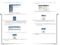
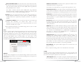
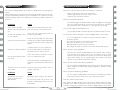
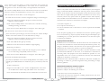
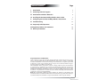
Page
Table of Contents
l.
Introduction
2
ll. Contacting Technical Support
3
lll. Introduction to Wireless Networks
4
IV. Installing the Actiontec 54 Mbps Wireless Access Point
7
V. Configuring the Actiontec 54 Mbps Wireless Access Point
11
VI Troubleshooting
21
VII Frequently Asked Questions
22
VIII Regulatory Notices and Statements
24
IX Warranty Statements
26
Proprietary Notice and Disclaimer
Unless otherwise noted, this document and the information herein disclosed are proprietary to Actiontec Electronics, Inc the manufacturer. Any person or entity to whom this
document is furnished or who otherwise has possession thereof, by acceptance agrees that
it will not be copied or reproduced in whole or in part, nor used in any manner except to
meet the purposes for which it was delivered.
The information in this document is subject to change without notice and should not
be construed as a commitment by Actiontec the manufacturer. Although Actiontec the
manufacturer will make every effort to inform users of substantive errors, Actiontec the
manufacturer disclaims all liability for any loss or damage resulting from the use of this
document or any hardware or software described herein, including without limitation
contingent, special or incidental liability.
Note: PC is a trademark of IBM Corporation. Windows 98 , Windows 98 SE, Windows NT,
and Windows XP is a trademark of Microsoft Inc. All other brand or product names and logos
used in this manual are trademarks or registered trademarks of their respective holders.
Table of Contents
1
l
Introduction
Thank you for purchasing the Actiontec 54Mbps Wireless Access Point. This
Wireless Access Point is easy to use and easy to setup. If you like the freedom of
accessing your network from anywhere within your home or office, then take your
networking to the next level with the Actiontec 54Mbps Wireless Access Point. You
will be able to have full access to your network and share files, printers, and even
your High-Speed Internet access.
Contacting Technical Support
Actiontec Electronics prides itself on making high-quality, durable, high-performance products. If you should need assistance, the Actiontec Technical Support
Department is available 24 Hours a Day, 7 Days a Week to provide professional
support.
Package Contents
Make sure the following items came in this package:
Actiontec 54Mbps Wireless Access Point and power adapter
Accessories bag (lugs, screws, etc...)
This User’s Manual and Quick Start Installation Guide
Minimum System Requirements
PC Computer with an Ethernet Adapter configured for TCP/IP.
U.S. Contact:
Actiontec Electronics, Inc.
760 N. Mary Avenue
Sunnyvale, CA 94085
Phone: 1-888-436-0657
E-mail: [email protected]
Internet Browser (Microsoft Explorer, Netscape Navigator, etc..).
Microsoft Windows XP, 2000/Windows Millennium Edition, Windows 98
Second Edition (SE), Windows NT 4.0
Europe Contact:
Actiontec Europe Ltd.
Merlin House, Brunel Road
Theale, Berkshire
UK RG7 4AB
Tech Support: 0845 65 80411
E-mail: [email protected]
2
Introduction
Contacting Technical Support
3
ll
Introduction to Wireless Networks
lll
1. Prepare one computer that you will want to connect wirelessly.
(Install wireless network card and software).
A wireless network connects computers to each other using radiotechnology which
allows you the freedom to move around the area and work anywhere within reach
of an Access Point.
2. Configure the IP settings for this client computer.
The Actiontec 54Mbps Wireless Access Point supports the 802.11g wireless LAN
protocol and is backward compatible with 802.11b. The Access Point can be
connected to a wired network to allow communication between the wired network
and computers using Actiontec 54 Mbps Wireless Wireless PC Cards.
The technology is an extension to the existing Ethernet networking standard, so you
can connect the Actiontec 54 Mbps Wireless Access Point to an existing Ethernet
network.
4. Your 54 Mbps wireless network is now ready.
3. Install the Actiontec 54 Mbps Wireless Access Point.
lll
5. For further functionality and security, the Actiontec 54 Mbps Wireless Access
Point can be configured using any Web Broser.
6. Install other client computers if this is applicable to your environment.
Extending a wired network with one or more 54 Mbps Wireless Access Points
Adding Access Points to your network
Placement and connection of the Actiontec 54 Mbps Wireless Access Point depends
entirely on your specific (network) environment. The Actiontec 54 Mbps Wireless
Access Point can be used for the following configurations:
When the Actiontec 54 Mbps Wireless Access Point is used as an extension to a wired
network (figure 2), please make sure that the current wired network is completely
functional.
Creating a wireless network.
Extending an existing wireless network.
Connecting to a single computer.
Creating a wireless network
Your Actiontec 54 Mbps Wireless Access Point can be used to setup a wireless network as shown on figure 1. Follow the steps below to create a wireless network.
Figure 2. Extending a Wired Network
Note: Refer to the appropriate user manual for successful installation of
your wireless network.
Follow these steps to extend you wired network:
1. Install the Actiontec 54 Mbps Wireless Access Point and connect it to your
wired network.
2. You can now use the wireless network.
Figure 1. Creating a Wireless Network
Note: Refer to the appropriate user manual for successful installation of your
wireless network.
4
Introduction to Wireless Networks
3. For further functionality and security, the Actiontec 54 Mbps Wireless
Access Point can be configured using any Web Browser.
4. Install the wireless client computer(s).
Introduction to Wireless Networks
5
Connecting an Access Point directly to a computer
Your Actiontec 54 Mbps Wireless Access Point can be connected directly to your
computer as shown in figure 3.
lll
Installing the Actiontec 54 Mbps Wireless Access Point
This equipment is designed with utmost care for the safety of those who install
and use it. However, special attention must be paid to the dangers of electric shock
and static electricity when working with electronic equipment. All guidelines of
this manual and of the computer manufacturer must therefore be followed at all
times to ensure the safe use of the equipment.
Physical installation of the Actiontec 54 Mbps Wireless Wireless Access Point
lV
For best performance, and range, the Actiontec 54 Mbps Wireless Access point
needs to be placed in a flat hoizontal position with the antennae extended up as
shown in figure 4.
Figure 3. Connecting Directly to a Computer
Note: Refer to the appropriate user manual for successful installation of your
wireless network.
Follow these steps to connect your Actiontec 54 Mbps Wireless Access Point
directly to your computer:
1. Install a network interface card (NIC) in the computer you want to
connect the Actiontec 54 Mbps Wireless Access Point to.
2. Configure the IP settings for this client.
3. Install the Access Point.
Note: For this connection you need to use a cross-over Ethernet cable.
4. You can now use the wireless network.
5. For further functionality and security, the Actiontec 54 Mbps Wireless
Access Point can be configured using the Actiontec 54 Mbps Wireless
Access Point Locator software utility and the Web Interface.
6. Install the wireless client computer(s).
6
Introduction to Wireless Networks
Figure 4 Actiontec 54 Mbps Wireless Wireless Access Point
Installing the Actiontec 54 Mbps Wireless Access Point
7
The Actiontec 54 Mbps Wireless Access Point can be installed in 2 different ways:
Accessories such as screws and lugs to fasten the Access Point to a wall
are provided in the Accessories bag.
On a desktop.
Connecting the Access Point to a network
Determine a clear area within your desktop where the Actiontec 54 Mbps
Wireless Access Point can be placed in a horizontal position clear of
obstructions.
Now that your Actiontec 54 Mbps Wireless Access Point has been installed, it is
ready to be connected to the power outlet and to your wired network.
Ethernet Port
Power Port
lV
lV
Figure 5. Actiontec 54 Mbps Wireless Access Point on a desktop
Figure 7 Actiontec 54 Mbps Wireless Access Point connectors
Mounted on a wall.
Prior to drilling holes into a wall, make sure the wall area of interest is clear of
electrical wiring or water pipes.
Determine the position of the screws and mark with a pencil.
Drill holes in the wall at the location of the marks.
1. Attach the power adapter output connector to
the Actiontec 54 Mbps Wireless Access Point
and check the power LED to see if you are
connected properly.
Power LED
2. Identify the Ethernet port; this is located next to the power connector on
the Actiontec 802.11.Access Point.
Insert plastic lugs into the holes
Fasten the screws into the plastic lugs and make sure to leave a 3mm distance
as clearance between the wall and screw heads.
Mount the Actiontec54 Mbps Wireless Access Point onto the screws.
3. Attach the Ethernet cable to the Actiontec 54 Mbps Wireless Access Point
and connect the cable on the other end to either a hub in the network, or a
computer. Please see note below for proper connection.
If the Actiontec 54 Mbps Wireless Access Point is connected to a hub
or switch, a 'cross-over' Ethernet cable must be used.
If the Actiontec 54 Mbps Wireless Access Point is connected directly to
a computer, a 'straight' Ethernet cable must be used.
Figure 6. Actiontec 54 Mbps Wireless Access Point on a wall
8
Installing the Actiontec 54 Mbps Wireless Access Point
Installing the Actiontec 54 Mbps Wireless Access Point
9
LEDs
There are three LEDs (Light emitting diodes) on the Actiontec 54 Mbps Wireless
Access Point. These visual aids can help you verify proper operation.
Power
The power LED lights up when
the Access Point is connected to
a power source.
Network The network LED will blink
when the Access Point is connected
to a wired network
lV
Power
LED
Radio
LED
How to configure the Actiontec 54 Mbps Wireless Access Point
Configuring the Actiontec 54 Mbps Wireless Access Point means installing settings
with respect to the use of radio channels, security, identification, etc. You only need
to configure the Actiontec 54 Mbps Wireless Access Point when you want to change
these settings.
You can configure the Actiontec 54 Mbps Wireless Access Point through the Access
Pont Locator utlity provided in the Installation CD or via the Web Interface. Locator
utlity provided in the Installation CD.
V
Radio
Ethernet
LED
Configuring the 54 Mbps Wireless Access Point
The radio LED blinks when the
Access Point is active.
Figure 7. Actiontec 54 Mbps Wireless Access Point LEDs
Starting the Access Point Locator Utility
The Access Point Locator utility helps you identify and modify the IP values of the
Access Point without launching the Web Interface.
1. Insert the Access Point Installation CD in your Computer’s CD-ROM Drive,
and close the drive tray, this will launch the installation process.
2. When the following screen appears, click on Install Software to continue.
3. When the following screen appears, click Next to continue.
10
Installing the Actiontec 54 Mbps Wireless Access Point
Configuring the Actiontec 54 Mbps Wireless Access Point
11
4. When the following screen appears, click Finish to continue.
8.
When the following screen appears, enter the appropriate values and
click Apply.
9. If you are not sure of the IP addressvalues, you can click on the Auto
IP Icon. This will configure the Access Point properly.
5. Once the Installation is complete, from the Windows Desktop click on the
Access Point Locator Icon.
V
Note: The Access Point Locator allows the end user to identify the IP address of
the Access Point as an aid to Adjusting the Access Point’s
network address values, we reccommend keeping the factory defaults.
V
Note: Make sure you record the IP settings assigned by the Auto IP function.
We reccommend keeping the factory defaults if you are not sure
10. Once completed, click on the Internet Explorer Icon on the Access
Point Locator Window in order to adjust the Access Point Settings
using the Web Interface
6. The Access Point Locator will scan for any available Access Points and
display their information.
.
7. If you wish to change the factory defaul values, click on the configure icon.
Note: The Access Point can also be adjusted manually by accessing it from
any browser.
Note: Make sure you record the current IP settings prior to changing the current
configuration.
12
Configuring the Actiontec 54 Mbps Wireless Access Point
Configuring the Actiontec 54 Mbps Wireless Access Point
13
Starting the Web Interface
Once the Actiontec 54 Mbps Wireless Access Point Configuration Utility has finished
and the Actiontec 54 Mbps Wireless Access Point is available for configuration in the
network, configure it by using any Web Browser.
Assoc
Assoc ia tions
To access the associations page, click on the “Assoc” tab. Here you can verify the
devices that are currently connected to your 54 Mbps Wireless Access Point. The
associated device’s MAC (Media Access Control) address will be displayed inside the
green MAC Address field.
1. Launch the Web Browser and type the following address in the Address Field
http:\\192.168.1.240 , press Enter to continue.
2. Enter the Username: Admin and Password: Admin - Press enter to continue.
MAC address
V
3. When the following screen appears, begin configuring your 54 Mbps Wireless
Access Point.
W ireless
ireless
Here you can install items such as the Performance Mode, identification of the
device, radio channel to be used as well as the Transmition rate or data speed.
Visibility Status: When invisibility is selected, the Access Point will be protected against its discovery from wireless “sniffer” programs. In order to connect to the Access Point, all wireless clients must use the Access Point’s designated SSID value.
Phy Profiles Mode: There are five options you can choose from.
802.11g onl: This option supports only 802.11g Products.
Web Interface Contents
The Web Interface application allows you to view and carry out setting changes for
the Actiontec 54 Mbps Wireless Access Point. Refer to this list when changing your
Actiontec 54 Mbps Wireless Access Point internal settings.
Info
Info
This page contains information about the Actiontec 54 Mbps Wireless Access Point.
802.11g Maximum Performance: This option configures the Access Point
to only allow connectivity to 802.11g devices operating at a peak data rate
of up to 54 Mbps. By selecting this performance mode, all 802.11b devices
will be excluded. For increased performance, select “Short Preamble”
from the Advanced page.
Maximum Interoperability using 802.11 b/g Mixed Mode: This option
configures the Access Point to allow automatic detection of 802.11b and
802.11g devices connected to the wireless network.
This is the Initial Page on the 54
Mbps Wireless Access Point.
By selecting this performance mode, all devices wirelessly linked to the
Access Point will operate at reduced data rates than those while operating
in their respective native protocol.
This is only an information screen
and does not allow changes.
802.11 b/g Mixed Mode Long: A Long Preamble provides universal
compatability for devices connecting to the Access Point.
802.11b only: Reduces all traffice to 802.11b standards of 11 Mbps.
14
Configuring the Actiontec 54 Mbps Wireless Access Point
Configuring the Actiontec 54 Mbps Wireless Access Point
15
V
V
Wireless Network Name (SSID): This is the name of the Access Point on the wireless network. Client devices associated to this network may need to know this
name. The default Wireless Network Name (SSID) while using Maximum
Interoperability mode is: Actiontec.
Maximum associated stations: This field is used to specify the number of associated wireless devices at any given time.
The default Wireless Network Name (SSID) while using Maximum
Performance mode is: Actiontec (Uppercase A, and lower case ctiontec). This
is necessary in order to enable 802.11g 54Mbps operation.
Fragmentation threshold: Use this field to specify the maximimum data packet
size for wireless transmitions to and by the Access Point. Packet data will be
fragmented to the specified size to maintain performance in a noisy network..
Channel: This is the radio channel that the Access Point will operate on,
if you experience interference you may need to try different channels.
Available channels are separated by frequencies, channels 1-11 operate at
2.4GHz.
RTS threshold: Use this field to specify the maximimum data packet size before
using the RTS/CTS. This is usefull to maintain performance in a noisy network environment or to prevent hidden nodes from degrading overall network performance.
Transmission rate (Mbits/s): This is the speed at which the Access Point will
transmit data. Normally, you should select “Best” as your
trasmission rate. You may select a low or high fixed trasmit rate if your
network is unusually noisy or quiet.
Beacon Period: Beacons are sent out by the access point in order to alert wireless client devices of its current status. These beacons are sent at intervals
measured in miliseconds. The value you choose may affect the wireless network’s performance.
When completed with changes in the Wireless Page, click on “Save” to make
the changes on the Access Point.
DTIM Period: Delevery Traffic Infomation Message provides wireless client
devices information on the actual traffic within the wireless network. This
information is delivered in intervals that are set based on the number of beacons. Therefore, if the DTIM period is 1, a DTIM will be transmitted every
time there is a beacon. If the DTIM period is 2, a DTIM will be
transmitted every two beacon tranmissions.
A c c ess
In order to protect against unauthorized network access the Access Point can allow
Access to devices that are only registered within the Access Control page.
By selecting “Enable access control:”, access will be granted only to devices that are
registered in the MAC address list. To register a device on the Access Control page,
enter the MAC (Media Access Control) address for each device to be
associated in the MAC Address field. Access Control is enforced immediately after
the address has been entered.
The number of associated devices at any given time range from 0 to 235.
Maximum Burst Time: This is also known as PRISM NitroTM technology. The
technology uses standard-compliant methods to eliminate collisions in
mixed-mode networks, while greatly increasing the performance of both
pure 802.11g and mixed 802.11b/g networks. The setting is for the amount
of time the radio will be resurped to send data without requiring an ACK.
This number is in units of microseconds. A typical value would be 1000
microseconds. When this number is zero, bursting is disabled.
Enable PSM Buffer: This option enables support for the stations that are in
power save mode.
Once you adjust the settings, click on save and reboot the Access Point.
A d v anced
anced
This page allows configuration of the advanced settings within the Access Point.
Wireless network performance can be enhanced by finding the best setting for your
environment.
Each advanced feature must be manually set.
16
Configuring the Actiontec 54 Mbps Wireless Access Point
S ecurit y
In order to protect against unauthorized network access, strong encryption and
authentication can be enabled to further enhance security. This page allows you set
the security and ecryption options for the Access Point.
WEP Configuration: WEP is the wireless encryption standard implemented in
the Access Point. To use it, a client device must provide a key that will be
Configuring the Actiontec 54 Mbps Wireless Access Point
17
V
autheticated by the Access Point.
Keys are classified by their size, 64 bit, and 128 bit and should be 10 characters long.
Enable WEP: Check the Enable WEP box to enable it and set
Authentication to “Shared key”.
V
Access Point Name: This is the name that the access point will use to identify
itself to external configuration and Access Point Locator.
This is not the same as the SSID. If you are not using any programs like those
mentioned, you can leave it blank.
Once you adjust the settings, click on save and reboot the Access Point.
WEP key lenghts: Select the appropriate WEP key lenght by clicking
on the arrow, the selected length applies to all keys.
A dmin
Here you can change the password, reboot the access point, or rest all settings to
their factory default values. The default password is: Admin
WEP key 1 - 4 : Enter sequence of leters and numbers (0-9, A-F) to be
used as a WEP key. You can set up to four different WEP keys.
You must reboot the access point if any sestting have been changed.
For example, a 64 Bit key would be “012FC493E1”.
Default WEP key to use: Select the Default WEP key to be used by
clicking on the arrow. Data transmissions will always be encrypted using
the default key. The other keys can only be use to decrypt received data.
Authentication: There are three methods to authenticate a client to
the access point, Open, Shared Key or Both.
- Open- allows anyone to authenticate to the access point.
- Shared Key- allows only stations that know the keys to authenticate.
- Both- allows a station to use either mode.
IP A ddr
Here you can configure the IP address used by the Web and TFTP servers running
on the Access Point, you can specifiy whether you are using a Static IP or are using
a DCHP address provided by a server in your network. These options will not go
into effect until the Access Point is rebooted.
IP Address Mode: Click on the option better suited for your needs.
Static: Check this box to use the IP settings specified on this page.
DHCP: Check this box to use the IP settings specified by a DHCP
server on your network.
Default IP Address: Enter the IP address for the access point.
V
User name: This is the user name you must type to gain access to the acces
point and make changes to these pages. The default Username is: Admin
Administrator Password: This is the password you must type to gain access to
the access point and make changes to these pages. You must enter the same
password in both entry fields. The default Password is: Admin
Once you adjust the settings, click on save and reboot the Access Point.
Reboot Access Point: By clicking on Reboot, you will perform a soft
restart of the access point.
Reset to factory defaults: By clicking on Reset, you will reset the access point to
its original factory values.
Upgrade Firmware: Select the Browse button to select the new firmware firle
that you downloaded from the Actiontec Technical Support website. Once
you have selected the file, click “Upload”. (Note: The firmware upgrade
process can take up to 60 seconds. )
H elp
We are constantly working to breing you better products and solutions. This section
will contain infomation to help you get the most out of your Actiontec 54 Mbps
Wireless Access Point.
Default Subnet Mask: Enter the subnet mask address, this specifies the number
portion of an IP address. The default value for the access point is:
255.255.255.0.
Default Gateway: Enter the IP address for the gateway that connects you to
the Internet.
18
Configuring the Actiontec 54 Mbps Wireless Access Point
Configuring the Actiontec 54 Mbps Wireless Access Point
19
l
ll
lll
Troubleshooting
Frequentlly Asked Questions
The Actiontec 54 Mbps Wireless Access Point is a reliable device and its designed to
operate
unattended. We have recognized some of the potential problems that may arise during setup and installation, therefore; we have compiled a set of solutions to the most
common problems. These answer will help you in achieving a flawless operation of
the device.
How far can I be from the access point and maintain a connection?
Vl
Vll
Solution
Is the Actiontec 54 Mbps
Wireless Access Point powered
up?
Check the power LED, Check if the access
point is connected to an electrical source.
Is there a Network connection?
Vlll
Client cannot make connection.
lX
X
Has the proper Network cable
been used?
Check the radio signal LED, Check for
possible range problems.
A wireless client is not (yet) connected to
the Access Point. Refer to the manual of
the wireless client on how to connect.
Yes, provided the DSL or Cable modem have an Ethernet UTP connector.
Yes, to accomplish this you need to set up your network as follows:
1. Install a gateway.
2. Connect the gateway to your internet connection.
3. Connect the gateway to your Access Point.
4. Install Wireless network cards in your clients.
5. Configure the clients to connect to the Access Point and the gateway.
Vlll
lX
Yes, when the Actiontec 54 Mbps Wireless Access Point is used in conjunction with other Access Points as in the case of campuses, users can roam
within the network provided all Access points are set correctly. Although the
device allows roaming, it is not a signal repeater and is limited to the range
between the Access Point and the client computer.
Your browser uses a proxy
server to connect to the
Web Interface.
Reconfigure proxy settings in your browser.
In any browser, make sure you have st the
browser to enable ‘Bypass Proxy server for
local address’
Troubleshooting
20
No, the Actiontec 54 Mbps Wireless Access Point is not an Integrated Access
Device (IAD), for network traffic filtering capabilities a firewall or similar
must be used.
No, the Actiontec 54 Mbps Wireless Access Point is not designed to track the
load on the network resources, this is just a data transport device.
How do I unlock the Access Point?
The Actiontec 54 Mbps Wireless Access Point factory default settings that allow
immediate access without configuration. The AP Locator utility has been provided
for further configuring of the device, the Actiontec 54 Mbps Wireless Access Point
20
Frequently Asked Questions
X
Xl
Does it provide network traffic filtering capabilities?
Does it provide load balancing capabilities?
Solution
Left Footer
Vll
Does it provide roaming capabilities?
AP Locator does not find the Check the power plug and make sure it is
properly connected.
Access Point.
20
Vl
Can I share the internet through the Actiontec 54 Mbps Wireless Access Point?
If the Access Point is connected to a hub, a
‘cross-over’ cable must be used
Possible Cause
lV
V
Can I connect a DSL or Cable Modem to it?
Check the network LED, the Access Point
may take up to a minute to find an IP Address
it can use if Auto IP is used to assign an IP
address.
If the Access Point is connected directly to a
computer, a normal Ethernet cable must be
used.
Xl
lll
How fast is the Wireless Network?
The rated throughput at optimal conditions is that of 54Mbps, this throughput
does vary on distance from the access point and the amount of attenuation
(physical barriers such as walls, glass, etc..) the signal must go through.
Possible Cause
No link with the Wireless card
in your computer.
ll
Range for this device varies on the environment.
Indoors approximately. 50 meters (150 ft.) or more.
Outdoors up to 300 meters (1000 ft.)
lV
V
l
Right Footer
21
l
can be locked to prevent changes to security and network access through Ap
Locaor. The Actiontec 54 Mbps Wireless Access Point can be unlocked either
through the use of the AP Locator Utility or through hardware unlock feature.
ll
The Actiontec 54 Mbps Wireless Access Point unlock/reset button is found below
the power connector and UTP (Ethernet) connector. It is a small red button.
lll
How do I unlock the Access Point so I can reconfigure it?
To unlock the Access Point so that the configuration changes are allowed again:
1. Press the red button found below the power connector and UTP
(Ethernet) connector briefly.
lV
2. The Actiontec 54 Mbps Wireless Access Point lock is unlocked. All settings,
including IP settings, are retained.
V
3. You can now use the Web Interface to manage the Access Point again.
Vl
Vll
If the reset button is pressed longer, more than 5 seconds, the Actiontec 54 Mbps
Wireless Access Point will be reset to the default factory settings:
1. Press the red button found below the power connector and UTP
(Ethernet) connector and keep it pressed down.
3. Release the reset button when the LED has stopped lighting.
4. All settings are deleted.
X
5. Use the KickStart utility to install new IP settings.(If you have a DHCP
server the IP settings will probably remain the same.)
Xl
6. You can now use the Web Interface to manage the Access Point again.
Can I launch the Web Interface Manually?
If you know the IP address of the Actiontec 54 Mbps Wireless Access Point, you can
manually open the Web Interface in a web browser, just as you would any other web
page.
1. Open a web browser.
2. Type in the web address of the Actiontec 54 Mbps Wireless Access Point
on the address bar as follows: http://IP address of the Access Point/
3. You can bookmark the web address for the web Interface for easier access.
22
Left Footer
Frequently Asked Questions
Wireless LAN, Health and Authorization for use Radio frequency electromagnetic
energy is emitted from Wireless LAN devices. The energy levels of these emissions
however are far much less than the electromagnetic energy emissions from wireless
devices like for example mobile phones. Wireless LAN devices are safe for use by
consumers, because they operate within the guidelines found in radio frequency
safety standards and recommendations. The use of Wireless LAN devices may be
restricted in some situations or environments for example:
• On board of airplanes, or
• In an explosive environment, or
• In case the interference risk to other devices or services is perceived or identified
as harmful.
ll
lll
lV
V
In case the policy regarding the use of Wireless LAN devices in specific organizations or environments (e.g. airports, hospitals, chemical/oil/gas industrial plants, private buildings etc.) is not clear, please ask for authorization to use these devices prior
to operating the equipment.
Vll
Vlll
2. The radio LED will first light up constantly.
lX
l
Vl
How do I reset the Access Point to its factory settings?
Vlll
Regulatory Notices and Statements
22
Regulatory Information/disclaimers
Installation and use of this Wireless LAN device must be in strict accordance with
the instructions included in the user documentation provided with the product. Any
changes or modifications made to this device that are not expressly approved by the
manufacturer may void the user’s authority to operate the equipment.
The Manufacturer is not responsible for any radio or television interference caused
by unauthorized modification of this device, or the substitution or attachment of
connecting cables and equipment other than manufacturer specified. It is the
responsibility of the user to correct any interference caused by such unauthorized
modification, substitution or attachment.
Manufacturer and its authorized resellers or distributors will assume no liability for
any damage or violation of government regulations arising from failing to comply
with these guidelines.
USA-FCC (Federal Communications Commission) statement
This device complies with Part 15 of FCC Rules.
Operation is subject to the following two conditions:
1. This device may not cause interference, and
2. this device must accept any interference, including interference that may cause
un-desired operation of this device.
22
Regulatory Notes and Statements
Right Footer
23
lX
X
Xl
l
ll
lll
lV
V
Vl
FCC Interference Statement
This device complies with Part 15 of FCC Rules., as well as ICES 003 B / NMB
003 B. Operation is subject to the following two conditions: (1) this device may
not cause harmful interference, and (2) this device must accept any interference
received, including interference that may cause undesirable operation.
Modifications not expressly authorized by Actiontec Electronics may invalidate
the user's right to operate this equipment.
Actiontec Electronics, Inc. Limited Warranty
l
Hardware: Actiontec Electronics Inc. warrants to the end user (“Customer”) that this
hardware product will be free from defects in workmanship and materials, under
normal use and service, for twelve (12) months from the date of purchase from
Actiontec Electronics or its authorized reseller.
ll
This equipment has been tested and found to comply with the limits for a Class B
digital device, pursuant to Part 15 of the FCC Rules. These limits are designed to provide reasonable protection against harmful interference in a residential installation.
This equipment generates, uses, and can radiate radio frequency energy. If not
installed and used in accordance with the instructions, it may cause harmful interference to radio communications. However, there is no guarantee that interference
will not occur in a particular installation.
If this equipment does cause harmful interference to radio or television reception,
which can be determined by turning the equipment off and on, the user is encouraged to try and correct the interference by one or more of the following measures:
Actiontec Electronics’ sole obligation under this express warranty shall be, at
Actiontec’s option and expense, to repair the defective product or part, deliver to
Customer an equivalent product or part to replace the defective item, or if neither
of the two foregoing options is reasonably available, Actiontec Electronics may, in its
sole discretion, refund to Customer the purchase price paid for the defective product. All products that are replaced will become the property of Actiontec Electronics
Inc. Replacement products may be new or reconditioned. Actiontec Electronics warrants any replaced or repaired product or part for ninety (90) days from shipment,
or the remainder of the initial warranty period, whichever is longer.
Vll
Vlll
lX
X
Xl
1. Reorient or relocate the receiving antenna.
2. Increase the distance between the equipment and the receiver.
3. Connect the equipment to an outlet on a circuit different from that to which the
receiver is connected.
4. Consult the dealer or an experienced radio/TV technician for help.
FCC Radio Frequency Exposure statement
This Wireless LAN radio device has been evaluated under FCC Bulletin OET 65C
and found compliant to the requirements as set forth in CFR 47 Sections 2.1091,
2.1093, and 15.247 (b) (4) addressing RF Exposure from radio frequency devices.
The radiated output power of this Wireless LAN device is far below the FCC radio
frequency exposure limits.
Nevertheless, this device shall be used in such a manner that the potential for human
contact during normal operation is minimized. When using this device, a certain separation distance between antenna and nearby persons has to be kept to ensure RF
exposure compliance. In order to comply with RF exposure limits established in the
ANSI C95.1 standards, the distance between the antennas and the user should not
be less than 20 cm (8 inches).
Export restrictions
This product or software contains encryption code which may not be exported or
transferred from the US or Canada without an approved US Department of
Commerce export license.
24
Left Footer
Regulatory Notes and Statements
24
lll
SOFTWARE: Actiontec Electronics warrants to Customer that each software program licensed from it will perform in substantial conformance to its program specifications, for a period of ninety (90) days from the date of purchase from Actiontec
Electronics or its authorized reseller. Actiontec Electronics warrants the media containing software against failure during the warranty period. The only updates that
will be provided are at the sole discretion of Actiontec Electronics and will only be
available for download at the Actiontec website, www.actiontec.com. Actiontec
Electronics’ sole obligation under this express warranty shall be, at Actiontec
Electronics’ option and expense, to refund the purchase price paid by Customer for
any defective software product, or to replace any defective media with software
which substantially conforms to applicable Actiontec Electronics published specifications. Customer assumes responsibility for the selection of the appropriate applications program and associated reference materials. Actiontec Electronics makes no
warranty or representation that its software products will meet Customer’s requirements or work in combination with any hardware or applications software products
provided by third parties, that the operation of the software products will be uninterrupted or error free, or that all defects in the software products will be corrected.
For any third-party products listed in the Actiontec Electronics software product
documentation or specifications as being compatible, Actiontec Electronics will
make reasonable efforts to provide compatibility, except where the non-compatibility is caused by a “bug” or defect in the third party’s product or from use of the
software product not in accordance with Actiontec Electronics published specifications or User Guide.
THIS ACTIONTEC ELECTRONICS PRODUCT MAY INCLUDE OR BE
BUNDLED WITH THIRD-PARTY SOFTWARE, THE USE OF WHICH IS
GOVERNED BY A SEPARATE END-USER LICENSE AGREEMENT.
24
Warranty Statements
Right Footer
25
lV
V
Vl
Vll
Vlll
lX
X
Xl
l
ll
lll
lV
V
Vl
Vll
Vlll
lX
X
Xl
THIS ACTIONTEC ELECTRONICS WARRANTY DOES NOT APPLY TO
SUCH THIRD-PARTY SOFTWARE. FOR THE APPLICABLE WARRANTY,
PLEASE REFER TO THE END-USER LICENSE AGREEMENT GOVERNING THE USE OF SUCH SOFTWARE.
OBTAINING WARRANTY SERVICE: Customer may contact Actiontec
Electronics Technical Support Center within the applicable warranty period to
obtain warranty service authorization. Dated proof of purchase from Actiontec
Electronics or its authorized reseller may be required. Products returned to Actiontec
Electronics must be pre-authorized by Actiontec Electronics with a Return
Merchandise Authorization (RMA) number marked on the outside of the package,
and sent prepaid and packaged appropriately for safe shipment, and it is recommended that they be insured or sent by a method that provides for tracking of the
package. The repaired or replaced item will be shipped to Customer, at Actiontec
Electronics’ expense, not later than thirty (30) days after Actiontec Electronics
receives the defective product.
Return the product to:
In the United States
Actiontec Electronics, Inc
760 North Mary Avenue
Sunnyvale, CA 94085
Actiontec Electronics shall not be responsible for any software, firmware, information
or memory data or Customer contained in, stored on, or integrated with any products returned to Actiontec Electronics for repair, whether under warranty or not
.
WARRANTIES EXCLUSIVE: IF AN ACTIONTEC ELECTRONICS’ PRODUCT DOES NOT OPERATE AS WARRANTED ABOVE, CUSTOMER’S
SOLE REMEDY FOR BREACH OF THAT WARRANTY SHALL BE REPAIR,
REPLACEMENT, OR REFUND OF THE PURCHASE PRICE PAID, AT
ACTIONTEC ELECTRONICS’ OPTION. TO THE FULL EXTENT
ALLOWED BY LAW, THE FOREGOING WARRANTIES AND REMEDIES
ARE EXCLUSIVE AND IN LIEU OF ALL OTHER WARRANTIES, TERMS
OR CONDITIONS, EXPRESS OR IMPLIED, EITHER IN FACT OR BY
OPERATION OF LAW, STATUTORY OR OTHERWISE, INCLUDING WARRANTIES, TERMS OR CONDITIONS OF MERCHANTABILITY, FITNESS
FOR A PARTICULAR PURPOSE, SATISFACTORY QUALITY, CORRESPONDENCE WITH DESCRIPTION, AND NON-INFRINGEMENT, ALL OF
WHICH ARE EXPRESSLY DISCLAIMED . ACTIONTEC ELECTRONICS
NEITHER ASSUMES NOR AUTHORIZES ANY OTHER PERSON TO
ASSUME FOR IT ANY OTHER LIABILITY IN CONNECTION WITH THE
SALE, INSTALLATION, MAINTENANCE OR USE OF ITS PRODUCTS.
ACTIONTEC ELECTRONICS SHALL NOT BE LIABLE UNDER THIS
WARRANTY IF ITS TESTING AND EXAMINATION DISCLOSE THAT
26
Left Footer
Warranty Statements
26
THE ALLEGED DEFECT OR MALFUNCTION IN THE PRODUCT DOES
NOT EXIST OR WAS CAUSED BY CUSTOMER’S OR ANY THIRD PERSON’S MISUSE, NEGLECT, IMPROPER INSTALLATION OR TESTING,
UNAUTHORIZED ATTEMPT TO OPEN, REPAIR OR MODIFY THE
PRODUCT, OR ANY OTHER CAUSE BEYOND THE RANGE OF THE
INTENDED USE, OR BY ACCIDENT, FIRE, LIGHTNING, OTHER HAZARDS OR ACTS OF GOD.
LIMITATION OF LIABILITY: TO THE FULL EXTENT ALLOWED BY LAW,
ACTIONTEC ELECTRONICS ALSO EXCLUDES FOR ITSELF AND ITS
SUPPLIERS ANY LIABILITY, WHETHER BASED IN CONTRACT OR TORT
(INCLUDING NEGLIGENCE), FOR INCIDENTAL, CONSEQUENTIAL,
INDIRECT, SPECIAL, OR PUNITIVE DAMAGES OF ANY KIND, OR FOR
LOSS OF REVENUE OR PROFITS, LOSS OF BUSINESS, LOSS OF INFORMATION OR DATA, OR OTHER FINANCIAL LOSS ARISING OUT OF OR
IN CONNECTION WITH THE SALE, INSTALLATION, MAINTENANCE,
USE, PERFORMANCE, FAILURE, OR INTERRUPTION OF ITS PRODUCT,
EVEN IF ACTIONTEC ELECTRONICS OR ITS AUTHORIZED RESELLER
HAS BEEN ADVISED OF THE POSSIBILITY OF SUCH DAMAGES, AND
LIMITS ITS LIABILITY TO REPAIR, REPLACEMENT,OR REFUND OF
THE PURCHASE PRICE PAID, AT ACTIONTEC ELECTRONICS’ OPTION.
THIS DISCLAIMER OF LIABILITY FOR DAMAGES WILL NOT BE
AFFECTED IF ANY REMEDY PROVIDED HEREIN SHALL FAIL OF ITS
ESSENTIAL PURPOSE.
DISCLAIMER: Some countries, states or provinces do not allow the exclusion or limitation of implied warranties or the limitation of incidental or consequential damages
for certain products supplied to consumers, or the limitation of liability for personal
injury, so the above limitations and exclusions may be limited in their application
to you. When the implied warranties are not allowed to be excluded in their entirety, they will be limited to the duration of the applicable written warranty. This warranty gives you specific legal rights which may vary depending on local law.
DISPUTE RESOLUTION: The customer may contact the Director of Technical
Support in the event the Customer is not satisfied with Actiontec Electronics
response to the complaint. In the event that the Customer is still not satisfied with
the response of the Director of Technical Support, the Customer is instructed to
contact the Director of Marketing. In the event that the Customer is still not satisfied with the response of the Director of Marketing, the Customer is instructed to
contact the Chief Financial Officer and/or President.
GOVERNING LAW: This Limited Warranty shall be governed by the laws of the
State of California, U.S.A. excluding its conflicts of laws principles and excluding the
United Nations Convention on Contracts for the International Sale of Goods.
26
Warranty Statements
Right Footer
27
l
ll
lll
lV
V
Vl
Vll
Vlll
lX
X
Xl