1
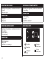
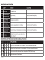
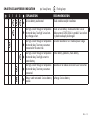
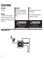
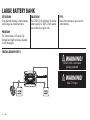
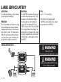
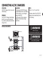
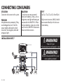
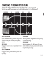
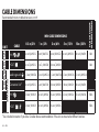
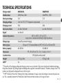
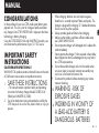
CONGRATULATIONS
on the purchase of your new CTEK professional battery management unit. This unit is part of a range of professional battery chargers from CTEK SWEDEN AB. It represents the latest
technology in battery charging.
Using the CTEK D250S DUAL and SMARTPASS products, you
can maximize the performance of your 12 V DC source.
IMPORTANT SAFETY
INSTRUCTIONS
California Proposition 65
WARNING: This product contains chemical known to the state
of California to cause cancer or reproductive toxicity.
1.
SAVE THESE INSTRUCTIONS
– This manual contains important safety and operating
instructions for battery charger Models D250S DUAL
(1044) and SMARTPASS (1058).
2. Use of an attachement not recommended or sold by the
CTEK may result in a risk of fire, electric shock, or injury to
persons.
3. When charging, batteries can emit explosive gases,
therefore it is essential to prevent flames and sparks. The
charger is designed for charging 12 V lead-acid batteries.
Do not use for any other purpose.
4. Always provide good ventilation when charging.
5. Make sure that cables used have sufficient cable area,
see CABLE DIMENSIONS.
6. Do not operate charger with damaged cord - replace the
cord immediately.
7. Never operate the charger if it has received a sharp blow,
been dropped or otherwise damaged in any way; take it
to a CTEK representative.
8. Do not disassemble charger; take it to the retailer when
service or repair is required. Incorrect reassembly may
result in a risk of electrical shock or fire.
9. Disconnect the products before attempting any maintenance or cleaning
WARNING - RISK OF
EXPLOSIVE GASES
a) WORKING IN VICINITY OF
A LEAD-ACID BATTERY IS
DANGEROUS. BATTERIES
10.
EN • 3
EN
MANUAL
GENERATE EXPLOSIVE GASES
DURING NORMAL BATTERY
OPERATION. FOR THIS
REASON, IT IS OF UTMOST
IMPORTANCE THAT, YOU
FOLLOW THE INSTRUCTIONS
EACH TIME YOU INSTALL THE
CHARGER.
b) To reduce risk of battery explosion, follow these instructions and those published by the battery manufacturer
and the manufacturer of any equipment you intend to use
in vicinity of battery. Review cautionary marking on these
products and on engine.
c) Disconnect battery poles before installation
d) D250S DUAL is not reverse polarity protected.
PERSONAL PRECAUTIONS
11.
a) Consider having someone close enough by to come to
your aid when you work near a lead-acid battery.
b) Have plenty of fresh water and soap nearby in case battery acid contacts skin, clothing or eyes.
4 • EN
c) Wear complete eye protection and clothing protection.
Avoid touching eyes while working near battery.
d) If battery acid contacts skin or clothing, wash immediately
with soap and water. If acid enters eye, immediately flood
eye with running cold water for at least 10 minutes and
get medical attention immediately.
e) NEVER smoke or allow a spark or flame in vicinity of battery or engine.
f) Be extra cautious to reduce risk of dropping a metal tool
onto battery. It might spark or short-circuit battery or other
electrical part that may cause explosion.
g) Remove personal metal items such as rings, bracelets,
necklaces, and watches when working with lead-acid
battery. A lead-acid battery can produce a short-circuit
current high enough to weld a ring or the like to metal,
causing a severe burn.
h) Use charger for charging a LEAD-ACID battery only. Do
not use battery charger for charging dry-cell batteries that
are commonly used with home appliances. These batteries may burst and cause injury to persons and damage to
property.
i) Never charge a frozen battery.
PREPARING TO CHARGE
12.
a) If necessary to remove battery from vehicle to charge,
always remove grounded terminal from battery first. Make
sure all accessories in the vehicle are off, so as not to
cause an arc.
CHARGER LOCATION
13.
a) Never place charger directly above battery being
charged; gases from battery will corrode and damage
charger.
b) Never allow battery acid to drip on charger when reading electrolyte specific gravity or filling battery.
c) Do not set a battery on top of charger.
14.
FOLLOW THESE STEPS WHEN
BATTERY IS INSTALLED IN
VEHICLE. A SPARK NEAR
BATTERY MAY CAUSE BATTERY
EXPLOSION. TO REDUCE RISK
OF A SPARK NEAR BATTERY:
a) Position cords to reduce risk of damage by hood, door or
moving engine part.
b) Stay clear of fan blades, belts, pulleys, and other parts
that can cause injury to persons.
c) Check polarity of battery posts. POSITIVE (POS, P, +)
battery post usually has larger diameter than NEGATIVE
(NEG, N, -) post.
d) Determine which post of battery is grounded (connected)
to the chassis. If negative post is grounded to the chassis
(as in most vehicles) see (e). The battery charger can
not be used with positive-grounded batteries.
e) For Negative-grounded vehicle, connect POSITIVE connector from battery charger to POSITIVE (POS, P, +)
ungrounded post of battery. Connect NEGATIVE connector from battery charger to vehicle chassis or engine block
away from battery. Do not connect to carburetor, fuel
lines, or sheet-metal body parts. Connect to a heavy gage
metal part of the frame or engine block.
f) When disconnecting charger, always do so in reverse
sequence of connecting procedure and break first connection while as far away from battery as practical.
EN • 5
EN
b) Be sure area around battery is well ventilated while battery is being charged.
c) Clean battery terminals. Be careful to keep corrosion from
coming in contact with eyes.
d) Add distilled water in each cell until battery acid reaches
level specified by battery manufacturer. Do not overfill.
For a battery without removable cell caps, such as valve
regulated lead acid batteries, carefully follow manufacturer’s recharging instruction.
e) Study all battery manufacturer’s specific precautions while
charging and recommended rates of charge.
f) Determine voltage of battery by referring to vehicles
manual.
15.
FOLLOW THESE STEPS WHEN
BATTERY IS OUTSIDE VEHICLE.
A SPARK NEAR BATTERY MAY
CAUSE BATTERY EXPLOSION.
TO REDUCE RISK OF
A SPARK NEAR BATTERY:
a) Check polarity of battery terminals. POSITIVE (POS,
P, +) battery post usually has a larger diameter than
NEGATIVE (NEG, N, -) post.
b) Attach at least a 24-inch-long 6-gauge (AWG) insulated
battery cable to NEGATIVE (NEG, N, —) battery post.
c) Connect POSITIVE charger connector to POSITIVE (POS,
P, +) post of battery.
d) Position yourself and free end of cable as far away from
battery as possible – then connect NEGATIVE charger
connector to NEGATIVE (NEG, N, -) post of battery.
e) Do not face battery when making the final connection.
f) When disconnecting charger, always do so in reverse
sequence of connecting procedure and break first connection while as far away from battery as practical.
6 • EN
SAFETY
• D250S Dual and SMARTPASS is designed for 12V leadacid batteries. Do not use the unit for any other batteries.
• Disconnect battery poles before installation
• D250S Dual is not sprak proof.
• The installation must include a fuse according to recommendations in table “CABLE DIMENSIONS”.
WARNING!
D250S DUAL and SMARTPASS is not
reverse polarity protected.
All installations on boats must follow
ISO 10133. Please note!
1.Connections from the battery must be fused close to the
battery.
2.Batteries must be permanently mounted in ventilated areas.
3.Cables must be placed in tubes, separated from cables for
110/230 V (shore power), or be attach to the surface every
300 mm.
4.Cables in the engine room must be rated to withstand
70°C/158°F
5.For a permanently connencet battery charger:
GROUNDING INSTRUCTIONS— This battery charger
should be connected to a grounded, metal, permanent
D250S DUAL
The D250S Dual has 2 inputs. The Service battery will be
charged from the alternator, solar panel, or both in combination. The solar panel adjusts itself to the Starter battery voltage.
The Starter battery will be charged and maintained directly by
the solar panel if the Service battery is fully charged.
D250S Dual
Solar panel +
Vehicle ground/
Solar panel –
Temperature sensor
L:2 m/6,5 feet
EN
wiring system; or an equipment-grounded conductor should
be run with circuit conductors and connected to equipmentgrounded terminal or lead on battery charger. Connections
to battery charger should comply with all local codes and
ordinances.
+IN
12V
+IN
Alternator
battery +
D250S DUAL
+OUT
Service
battery +
features:
• Multi-step 20 A temperature compensated battery charging
and battery maintenance.
• Battery separation of Starter and Service batteries.
• Maximum power point tracking for solar panels charging
the Service battery.
• Two power source inputs (alternator, solar, wind, Supply
battery and other).
• Coordination of the two inputs, allowing parallel operation.
• The solar input will also maintain the Alternator battery.
• Built in battery guard for the Alternator battery.
EN • 7
DEFINITIONS SOLAR PANEL
DEFINITIONS Alternator battery
Depending on the application, it could also be referred to as
- PV panel
- Photovoltaic panel
Depending on the application, it could also be referred to as
- Starter battery
CONNECTIONS
CONNECTIONS
- Solar panel
- Wind power
- Trailer coupling
- Alternator
- SMARTPASS Alternator +
DEFINITIONS SERVICE BATTERY
D250S DUAL Lamps
Depending on the application, it could also be referred to as
- House battery
- Domestic battery
- Consumer battery
CONNECTIONS
- Electrical equipment
- Battery bank
- SMARTPASS service battery +
+IN
Error lamp
Alternator
battery lamp
Power lamp
Solar power
lamp
8 • EN
Service
battery lamp
D250S DUAL
LAMP
Function
Power lamp
D250S DUAL connected
correctly, ready to use
Alternator battery lamp
Alternator running
Service battery lamp
Charging of Service
battery
Solar panel lamp
Solar panel in operation
D250S DUAL Lamp INDICATION
DURING NORMAL OPERATION
D250S DUAL Lamp Error INDICATION
Steady lamp
Flashing lamp
Lit with a steady glow
Service battery charged by the
alternator
Service battery charged by the solar
panel
Service battery charged by both the
alternator and solar panel
Service battery fully charged.
Alternator battery maintained by the
solar panel
When the Power lamp flickers, the unit
is in power saving mode
Explanation
High temperature detected at either unit or service battery
Recommendation
Consider relocationg unit and/or service battery
Service battery connection problem detected
Check Service battery connection and fuse
Service battery connection problem detected
Check Service battery connection and fuse
Service battery connection problem detected
Check Service battery connection and fuse
EN • 9
EN
D250S DUAL Lamp FUNCTION
SMARTPASS
SMARTPASS can operate as a stand-alone unit, but works best
in combination with D250S Dual. The SMARTPASS creates
a priority path for charging the Service battery to recharge
it more quickly and efficiently. Attached energy sources like
solar, wind or shore power will charge both the Service and
the Starter batteries through the SMARTPASS. Service batteries
that are overheated due to age, high ambient temperature or
other battery problems will be protected from high alternator
current.
• Maintenance charge of Starter battery, which simplifies
installation with fewer components.
• Simplified installation of AC/DC chargers (shore power).
Only one output from the AC/DC charger needed.
The CTEK SMARTPASS is designed to work together with
1-2 CTEK D250S Dual, but can also be used alone.
Alternator
battery +
Service
battery +
SMARTPASS
FEATURES:
The CTEK SMARTPASS adds additional functionality for higher
output alternators, larger battery banks and/or high parallel
loads.
• Separation of consumers and Service batteries during
charging, which improves the charging capacity significantly, and lowers the consumer voltage, which increases
expected service life of lights and other electronics.
• Service battery watch, which avoids harmful deep discharges that otherwise would shorten battery life. The battery watch also protects navigation, radio and emergency
light from being out of electricity.
• Over-temperature protection of Service battery. High battery temperature could significantly reduce battery life.
10 • EN
+IN
Negative cable
connection M8
L: 0.3 m/12 inches
+OUT
12V
SMARTPASS
+OUT
Consumers +
Temperature sensor
L: 2 m/6.5 feet
DEFINITIONS CONSUMERS
Depending on the application, it could also be referred to
as
- Starter battery
Depending on the application, it could also be referred to
as
- Electrical equipment +
CONNECTIONS
CONNECTIONS
- Trailer coupling
- Solar panel
- Wind power
- Alternator
- D250S DUAL Alternator battery +
- Electrical equipment
SMARTPASS LampS
1
DEFINITIONS SERVICE BATTERY
Depending on the application, it could also be referred to
as
- House battery
- Domestic battery
- Consumer battery
CONNECTIONS
- Electrical equipment
- Battery bank
- D250S DUAL Service battery +
EN
DEFINITIONS Alternator battery
3
2
+IN
Error lamp
Power lamp
1.Service battery
charging lamp
4
3.Alternator battery
charging lamp
4.Service battery
consumption lamp
12V2.Alternator battery con-SMARTPASS
sumption lamp
EN • 11
SMARTPASS Lamp FUNCTION
Lamp
Steady
Flashing
Power lamp
Unit ready to use
2
Alternator battery
consumption lamp
Engine running
1
Service battery
charging lamp
Charging Service battery
4
Service battery
consumption lamp
Consumers powered by Service battery
3
Alternator battery
charging lamp
Alternator battery maintained by Service battery Too high current through relay
Error lamp
Indicates that an error has occurred. See the
table to the right.
Too high current through relay
Too high current through relay
SMARTPASS Lamp INDICATION DURING NORMAL OPERATION
2
1
4
3
Explanation
High current from alternator to service battery. Consumer powered by alternator
Reduced current from alternator to service battery. Consumer powered by alternator
Consumer powered by alternator. Battery charged by D250S Dual charger
Pulse maintenance of starter battery
12 • EN
2
1
4
3
Steady lamp
Flashing lamp
Explanation
Service battery overheated
Recommendation
Check condition and/or installation
Too high current through or temperature
at internal relay. Too high Service battery charge current.
Too high current through or temperature
at internal relay. Too many consumers
connected at the same time.
Too high current through or temperature
at internal relay. Too high current to
starter battery.
Too high current through or temperature
at internal relay. Too many consumers
connected.
Battery watch activated. Service battery
too low
Check service battery. Reduce alternator size or
add one more D250S DUAL in parallel. Service battery bank too deeply discharged.
Consider relocation of unit. Reduce power usage.
Starter battery problems, check battery.
Relocate unit or reduce concurrent use of consumers.
Recharge Service battery
EN • 13
EN
SMARTPASS Lamp ERROR INDICATION
INSTALLATION of unit
1. Attach the temperature sensor holder on a flat surface on
one Service battery. Position it as close as possible to a
positive post.
2. Use the included drill template. Wiring is simplified if the
units are installed according to the drill template, but other
setups are possible.
3. Install the unit(s) on a surface where it can be properly
fixed and where the unit is not exposed to fuels, oils or
splashes of dirt.
4. Mount the unit with screws intended for the surface and
attach it with one screw in each of the four holes in the
corners of the unit. See picture 1. Mount the unit with M4
or ST4.2 screws. The required torque depends on the surface for mounting. Fig. 1 shows a CTEK D250S. The same
procedure is used for all devices.
5. Attach the cables and mount the cable screws with a
torque of 7 Nm/62 Lb-In. Use tool – hand power without
tools is not enough.
6. The ground cable of the SMARTPASS should be connected to the ground screw of the DUAL or to any convinient
ground connection point.
14 • EN
Figure 1
WARNING!
D250S DUAL and
SMARTPASS is not reverse
polarity protected.
Disconnect battery poles
before installation.
2Nm/18 Lb-In
INSTALLATION OF CABLES
Figure 2
Allen key
7Nm/62 Lb-In
WARNING!
D250S DUAL is not spark
proof. Provide for good
ventilation.
DRILL TEMPLATE
EN
168mm/6⅝ inches
90,6mm/3,57 inches
120mm/4,72 inches
210,6mm/8,29 inches
0, Ø4
19 ,9
in mm
ch
es
EN • 15
SOLAR PANEL
SITUATION
Solar panel.
PROBLEM
A solar panel with 36 cells produces
maximum power at about 17 V. Many
regulator reduce the voltage by “burning
off” energy.
SOLUTION
The D250S DUAL searches for the
Maximum Power Point and charges
the battery perfectly with very high
efficiency.
WARNING!
D250S DUAL is not reverse
polarity protected
INSTALLATION SHEET 1
+IN
12V
+IN
16 • EN
D250S DUAL
+OUT
TIP 1
Mount the temperature sensor on the
Service battery.
Boat: All installation should be done in
accordance with ISO10133.
WARNING!
•Max 23 V input
•Do not connect two solar panels in series
SITUATION
One alternator feeding a Starter battery
and a small Service battery.
PROBLEM
The Service battery will take a very long
time to recharge due to low alternator
voltage. Due to this, the battery will
underperform and die prematurely.
SOLUTION
The D250S DUAL charges the Service
battery quickly and very efficiently. The
battery will be fully charged, produce
more and last significantly longer.
TIP 2
Refer to Tip 1.
Alternators with voltage sensor cables
should connect this on the Starter battery
Caravan/trailer: For 13-pole contact,
connect D250S DUAL alternator battery
+ to pin #9. Connect pin #13 to D250S
DUAL vehicle ground –.
WARNING!
D250S DUAL is not reverse
polarity protected
WARNING!
Max 23 V input
INSTALLATION SHEET 2
+IN
12V
+IN
D250S DUAL
+OUT
EN • 17
EN
SMALL SERVICE BATTERY
LARGE BATTERY BANK
SITUATION
One alternator feeding a Starter battery
and a large Service battery bank.
PROBLEM
The Starter battery will not be fully
charged and might not always be able
to start the engine.
SOLUTION
The D250S DUAL recharges the Starter
battery quickly to 100%, which guarantees trouble-free engine starts.
INSTALLATION SHEET 3
TIP 3
Mount the temperature sensor on the
Starter battery.
WARNING!
D250S DUAL is not reverse
polarity protected
+IN
12V
+IN
18 • EN
D250S DUAL
+OUT
WARNING!
Max 23 V input
SITUATION
One alternator and a Solar panel feeding a Starter battery and a small Service
battery.
SOLUTION
The D250S Dual charges the Service
battery quickly and very efficiently
from both the Alternator and the Solar
panel. The Solar panel produces at its
maximum power point when the engine
is off. When both the Solar panel and
the Alternator are on, the Solar panel
adjusts to the Alternator. The battery will
be fully charged, produce more and last
significantly longer.
PROBLEM
The Service battery will take a very long
time to recharge due to low alternator
voltage. The Solar panel is difficult to
synchronize with the alternator. Due to
these issues, the battery will underperform and die prematurely.
INSTALLATION SHEET 4
TIP 4
See Tip 1 and Tip 2.
EN
SOLAR PANEL
WARNING!
D250S DUAL is not reverse
polarity protected
WARNING!
+IN
12V
+IN
D250S DUAL
+OUT
•Max 23 V input
•Do not connect two solar panels in series
EN • 19
LARGE SERVICE BATTERY
SITUATION
One alternator feeding a Starter battery
and a large Service battery.
PROBLEM
The Service battery will take a very long
time to recharge due to low alternator
voltage and restrictions in how the alternator current is used. The Solar panel is
difficult to synchronize with the alternator. Due to these issues, the battery will
underperform and die prematurely.
SOLUTION
The SMARTPASS separates the two battery banks when the engine is off. With
the engine on, the alternator charges
the service battery with its maximum
current until it has tapered off to the
D250S Dual max level. Then the D250S
DUAL charger finalizes the charge. The
recharge time is minimized. Solar panels
are easily integrated and synchronized if
a D250S Dual is used together with the
SMARTPASS.
INSTALLATION SHEET 5
TIP 5
See Tip 1, Tip 2 and Tip 4
Wires that are connected to both
SMARTPASS and D250S DUAL should
be connected to SMARTPASS.
WARNING!
•Max 23 V input
•Do not connect two solar panels in series
+IN
12V
D250S DUAL
+IN
+OUT
WARNING!
D250S DUAL and SMARTPASS is not
reverse polarity protected
+IN
+OUT
12V
20 • EN
SMARTPASS
+OUT
SITUATION
230/110 V charger for the Service and
Starter battery.
SOLUTION
The single output 230/110V charger is
connected directly to the Service battery.
The Starter battery is pulse charged
through SMARTPASS.
The solar panel will also maintaince
charge the Starter battery through
SMARTPASS.
PROBLEM
The 230/110 V charger should charge
both the Service and the Starter battery, and be synchronized with all other
energy sources.
INSTALLATION SHEET 6
TIP 6
See Tip 1, Tip 2, Tip 4 and Tip 5
The battery cables of the 230/110 V
charger are connected directly to the
Service battery.
WARNING!
12V
RECOND
•Max 23 V input
•Do not connect two solar panels in series
MODE
WARNING!
NORMAL RECOND NIGHT
+IN
12V
D250S DUAL
+IN
+IN
D250S DUAL and SMARTPASS is not
reverse polarity protected
+OUT
+OUT
12V
SMARTPASS
+OUT
EN • 21
EN
CONNECTING AC/DC CHARGERS
CONNECTING CONSUMERS
SITUATION
Connection of consumers to the system.
SOLUTION
Critical consumers are connected
directly to the battery. Others, such as
refrigerator, main light and heating are
connected to the SMARTPASS. When
the Service battery is down to a critical
level, then the SMARTPASS disconnects
these noncritical consumers.
PROBLEM
Many batteries die prematurely if they
are discharged too much. Too little
power might be delivered to critical
consumers, like navigation, radio and
emergency lights.
INSTALLATION SHEET 7
TIP 7
See Tip 1, Tip 2, Tip 4, Tip 5 and Tip 6.
High current consumers (>80 A) should
be connected directly to the Service or
Starter battery.
WARNING!
12V
RECOND
•Max 23 V input
•Do not connect two solar panels in series
MODE
WARNING!
NORMAL RECOND NIGHT
+IN
12V
D250S DUAL
+IN
+IN
+OUT
12V
22 • EN
+OUT
SMARTPASS
+OUT
D250S DUAL and SMARTPASS is not
reverse polarity protected
CHARGING PROGRAM D250S DUAL
The charger starts charging the target battery when the supply voltage exceeds 13.1 V for 5 sec (engine on).
The charger stops charging the target battery when the supply voltage drops below 12.8 V for 10 sec (engine off).
BULK
ABSORPTION
FLOAT
PULSE
11
2
3
4
5
CURRENT (A)
VOLTAGE (V)
EN
DESULPHATION
STEP 1 DESULFATION
Detects sulfated batteries. Pulsing current and voltage, removes
sulfate from the lead plates of the battery restoring battery
capacity.
STEP 2 BULK
Charging with maximum current until approximately 80 % battery capacity.
STEP 3 ABSORPTION
Charging with declining current to maximize up to 100 % battery capacity.
STEP 4 FLOAT
Maintaining the battery voltage at maximum level by providing
a constant voltage charge.
STEP 5 PULSE
Maintaining the battery at 95–100 % capacity. The charger
monitors the battery voltage and gives a pulse when necessary
to keep the battery fully charged.
EN • 23
CABLE DIMENSIONS
0.5 m/2 ft.
1 m /3 ft.
2 m /6 ft.
5 m /15 ft.
10 m /30 ft.
Fuse recommendations
Recommended minimum cable dimensions in mm²
+IN
4 mm2/AWG12
4 mm2/AWG12
4 mm2/AWG12
6 mm2/AWG10
10 mm2/AWG8
30A
+OUT
4 mm2/AWG12
6 mm2 /AWG10
10 mm2/AWG8
Min Cable Dimensions
CABLE
Lead to ground
SMARTPASS
D250S/D250S DUAL
UNIT
30A
1.5 mm2/AWG16 1.5 mm2/AWG16 1.5 mm2/AWG16 1.5 mm2/AWG16 1.5 mm2/AWG16
Connection Unit*
4 mm2/AWG12
6 mm2/AWG10
10 mm2/AWG8
10 mm2/AWG8
10 mm2/AWG8
+IN
16 mm2/AWG8
16 mm2/AWG6
16 mm2/AWG6
25 mm2/AWG4
25 mm2/AWG4
+OUT
16 mm2/AWG8
16 mm2/AWG6
16 mm2/AWG6
*Use included connectors if possible. Consider above recommendation if the units are mounted at different locations.
24 • EN
150A
150A
TeCHNICAL SPECIFICATIONS
Charger type
Battery types
Battery capacity
Dimensions
Insulation class
Weight
MPPT**
D250S DUAL
SMARTPASS
D250S Dual, 1044
SMARTPASS, 1058
23 V
23 V
14.4 V at 25°C/77°F temperature compensated
–
20 A
80 A
Less than 1Ah/month
Less than 1Ah/month
Less than 4%
–
-20°C to +50°C (-4°F to -122°F),
output power is reduced automatically at high temperatures
5-step fully automatic charging
–
All types of 12 V lead-acid batteries (WET, MF, Ca/Ca, AGM and GEL)
40–300 Ah
28–800 Ah
197 x 93 x 49 mm (7¾ x 3⅝ x 2 inches) L x W x H
IP65 (splash and dust proof)
0.73 kg/1,6 lbs
0.74 kg/1,6 lbs
Yes
–
EN
Charger model
Model number
Max input voltage
Charging voltage
Charging current
Back current drain
Ripple*
Ambient temperature
*) The quality of the charging voltage and charging current are very important. High current ripple heats the battery and ages
the positive electrode. High voltage ripple can damage other equipment connected to batteries. The battery chargers from CTEK
produce very high-quality voltage and current with low ripple
**) MPPT (Maximum Power Point Tracking) finds the best combination of supply current and voltage to maximize the power output. This is especially important for Photovoltaic (Solar) Panels and trailer campers with wiring constraints.
EN • 25
TEMPERATURE PROTECTION CTEK PRODUCTS ARE
SMARTPASS has a temperature sensor cable. The units will
PROTECTED BY
automatically protect the service battery if the temperature
LIMITED WARRANTY
CTEK SWEDEN AB, issues this limited warranty to the original
purchaser of this product. This limited warranty is not transferable. The warranty applies to manufacturing faults and
material defects for 2 years from the date of purchase. The
customer must return the product together with the purchase
receipt. This warranty is void if the battery charger has been
opened, handled carelessly or repaired by anyone other
than CTEK SWEDEN AB or its authorised representatives.
One of the screw holes in the bottom of the charger is sealed.
Removing or damaging the seal will void the warranty.
CTEK SWEDEN AB makes no warranty other than this limited
warranty and is not liable for any costs other than those mentioned above. For example, consequential damages are not
covered. Moreover, CTEK SWEDEN AB is not obligated to any
other warranty other than this warranty.
26 • EN
EP10156636.2 pending
US12/780968 pending
EP1618643
US7541778
EP1744432
EP1483817 pending
SE524203
US7005832B2
EP1716626 pending
SE526631
US7638974B2
EP09180286.8 pending
US12/646405 pending
EP1483818
SE1483818
US7629774B2
EP09170640.8 pending
US12/564360 pending
SE528232
SE525604
Designs
RCD 509617
US D575225
US D580853
US D581356
US D571179
RCD 321216
RCD 000911839
RCD 081418
RCD 001119911-0001
RCD 001119911-0002
RCD 081244
RCD 321198
RCD 321197
ZL 200830120184.0
ZL 200830120183.6
RCD 001505138-0001
RCD 000835541-0001
RCD 000835541-0002
D596126
D596125
RCD 001705138-0001
US D29/378528 pending
ZL 201030618223.7
US RE42303
US RE42230
2012–05–30
Trade marks
TMA 669987
CTM 844303
CTM 372715
CTM 3151800
TMA 823341
CTM 1025831
CTM 405811
CTM 830545751 pending
CTM 1935061 pending
V28573IP00
CTM 2010004118 pending
CTM 4-2010-500516
CTM 410713
CTM 2010/05152 pending
CTM1042686
CTM 766840 pending
SUPPORT
For latest revised user manual and CTEKs professional customer
support: www.ctek.com (EU), www.smartercharger.com (US).
By e-mail: [email protected] (EU), [email protected] (US).
By telephone: +46(0) 225 351 80 (EU), (330) 963-0981 (US).
20020400A
and charging voltage together are too high. Charging will then
only be performed by the D250S battery charger. The temperature should be measured close to the battery, therefore attach
the sensor to the battery.
Patents